Advertisement
Quick Links
Advertisement

Related Manuals for X-Rite VeriColor


Summary of Contents for X-Rite VeriColor
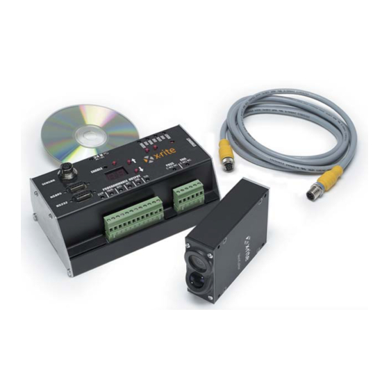
- Page 1 VeriColor ™ Identification System Troubleshooting and FAQ Manual Ver. 1.0...
- Page 2 Incorporated. This manual has been prepared solely for the purpose of assisting in the troubleshooting of this instrument. The contents of this manual are the property of X-Rite, Incorporated and are copyrighted. Any reproduction in whole or part is strictly prohibited. Publication of this information does not imply any rights to reproduce or use this manual for any purpose other than installing, operating, or maintaining this instrument.
-
Page 3: Table Of Contents
Table of Contents Introduction......................... 4 Hub Error Modes & Manual Operation ................5 Error Log in X-Rite Software ..................... 8 Hardware Problems......................12 Ethernet Setup Notes......................17 General FAQ........................18... -
Page 4: Introduction
Introduction The X-Rite VeriColor system was designed to be robust, reliable, and easy to use. This manual aims to provide useful information to aid integration or quickly resolve problems. If you cannot find the needed topic in this document, check X-Rite’s website (www.xrite.com) for the latest updates. This manual will be constantly updated as we hear feedback from customers like you. -
Page 5: Hub Error Modes & Manual Operation
Problem Topic Explanation/Solution Flashing “01” – System Each time VeriColor This is normal operation. VeriColor will remain Test Mode powers up, it will enter in this state until all sensor heads confirm they Test Mode. have warmed up to operating temperature and are ready to measure. - Page 6 Problem Topic Explanation/Solution Flashing “03” – Head The hub has tried to Refer to the Hardware area for Troubleshooting Timeout Error communicate to a specific under the topic of “Sensors that won’t head and failed. communicate”. Flashing “04” – During a measurement, one Take note of which “Output”...
- Page 7 Problem Topic Explanation/Solution Flashing “06” – Data User settings are corrupt. Two causes for this error are erroneous values Storage Error – cont. being sent to the hub from a software application, or a new version of hub firmware has a different data storage structure than the previous.
-
Page 8: Error Log In X-Rite Software
Error Log in X-Rite Software When using this table, some errors numbers that appear in software may be 3 digits. In those cases, the first digit always identifies in which head the error occurred. For example, an error of “220” means a Master Head List error occurred in head #2. - Page 9 List does not match the missing heads.” attempts to Connect in Master Head List This option will allow the user to attempt to use VeriColor Software. associated with this the system “as is”. This is not recommended for fixture” If a difference between the normal use as the system will do its best to hub’s current setup and...
- Page 10 List does not match the Standards” attempts to Connect in Master Head List This option gets chosen when the configuration VeriColor Software. associated with this for the “Reported Head List” column is to fixture” – cont. If a difference between the become the new setup for the current Fixture.
- Page 11 Problem Topic Explanation/Solution x30 – Failed The last measurement Clear errors and resume normal operation. If Measurement returned an error code that the same head fails again it has either been indicated one or more heads damaged or defective and requires replacement. as failing.
-
Page 12: Hardware Problems
Hardware Problems This section deals primarily with troubleshooting problems with the PLC discrete inputs. At the end of this section is the all important “missing heads” section. Problem Topic Explanation/Solution “Hub is initializing” Is the hub This message remains until the No problem, just wait until all locked up? hub has sent the OK to software... - Page 13 “Read” Input are used. command sent to the hub. Edit – cont. the current project in VeriColor Software and re-download the “Read” LED Indicator light does project making sure all the not work with input. – cont.
- Page 14 “Read” button on the hub still prompts measurements but none of the other buttons do anything (except Reset). Go into VeriColor software and under “Project” settings, “Disable buttons on hub after download” is selected. Unselect this if you wish to have the hub buttons remain active.
- Page 15 If all is well after a hub reset the first head should not be indicated as a problem on the LEDs or VeriColor Software when connecting. Now add on one head at a time, giving the hub a reset each time.
- Page 16 Once one bad head is replaced, others behind it may suddenly be functional again. Possibly only one head is defective/damaged. Use VeriColor Software through this process each time a change is made to the system. The best way to troubleshoot this problem is to remain in the “Connect”...
-
Page 17: Ethernet Setup Notes
Ethernet Setup Notes Make sure the instrument is connected to an Ethernet port (either part of an existing network or a direct connection to a PC with a 10Base-T Ethernet card installed). For an existing connection, an RJ-45 straight through cable is required. For a direct connection, an RJ-45 crossover cable is required. Before Ethernet communications can work, it is necessary to configure the instrument using application software designed to work with instrument. -
Page 18: General Faq
If the hub starts working normally within 7 or so seconds, see options below for possible solutions. If the Ethernet connection is not going to be used, turn it off using VeriColor software over the RS-232 port. Reset hub to verify fix.
Need help?
Do you have a question about the VeriColor and is the answer not in the manual?
Questions and answers