Table of Contents
Advertisement
Quick Links
Advertisement
Table of Contents

Related Manuals for X-Rite VeriColor Spectro


Summary of Contents for X-Rite VeriColor Spectro
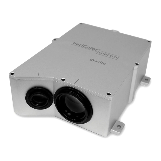
- Page 1 VeriColor Spectro ® Non-Contact Spectrophotometer Setup and Operator Manual...
- Page 3 Cet appareil numérique de la classe A est conforme à la norme NMB-003 du Canada. Equipment Information Use of this equipment in a manner other than that specified by X-Rite, Incorporated may compromise design integrity and become unsafe. WARNING: This instrument is not for use in explosive environments.
-
Page 4: Warranty Information
This product may be cover ed by one or more patents. Refer to the instrument for actual patent numbers. Copyright © 2007 by X-Rite, Incorporated “ALL RIGHTS RESERVED” X-Rite and VeriColor are registered trademarks of X-Rite, Incorporated. All other logos, brand names, and product names mentioned are the properties of their respective holders. Warranty Information X-Rite, Incorporated (“X-Rite”) warrants each instrument manufactured to be free of defects... -
Page 5: Table Of Contents
VeriColor Spectro System Operation Configuring the Software Options Administrative (Admin) Setup Language Tool Targeting a Part Calibration/Verification of the VeriColor Spectro Attaching the Calibration Tool Performing Calibration (first time, out of box) Performing Verification Performing Calibration (after verification failure) Calibration Configuration... - Page 6 V E R I C O L O R ® S P E C T R O General Maintenance Repair Information Cleaning the Spectro Instrument Lenses Cleaning the Calibration Tool Hardware Troubleshooting Appendices Specifications Accessories Electrical Interface Details...
-
Page 7: Overview
Status LED Indicator Unpacking and Inspection After removing the VeriColor Spectro from the shipping carton, inspect it for damage. If any damage has occurred during shipping, immediately contact the transportation company. Do not proceed with installation until the carrier's agent has inspected the damage. -
Page 8: Vericolor Spectro Installation
Mount the VeriColor Spectro to the fixture using the holes provided at each flange. VeriColor Spectro must be set to measure at a distance of 4” nominal to the measurement surface. If the instrument is mounted in a 0°/30° geometry (preferred), the distance is that from the center of the illumination lens to the sample. -
Page 9: Height Insensitivity
30°/0° illumination (see illustrations on previous page). The 0°/30° position is preferred for best repeatability and correlation to an X-Rite 964 or similar hand held spectrophotometer. Other angles may be used (example 7.5/37.5) but care must be taken to avoid sensing specular reflections from the illuminator. -
Page 10: Vericolor Spectro Dimension Drawing
V E R I C O L O R ® S P E C T R O VeriColor Spectro Dimension Drawing... -
Page 11: Cable Connection And Wiring
S P E C T R O Cable Connection and Wiring The VeriColor Spectro is designed to utilize the same cable configuration as the VeriColor Solo; however, due to the increased power requirements of the VeriColor Spectro, RS232 communication should be limited to cable lengths of less than 15 meters. For cable distances longer than 15 meters it is recommended that the RS485 communication scheme be utilized. - Page 12 Half Duplex. Also, connect the “#7 - CH-B 2 / RS485-RX-B (blue)” and “#8 – CH-A 1 / RS485-TX-B (red)” wires together for Half Duplex. **Use as common return to controller ground (insert a 10Ω resistor if voltage potential between the controller and VeriColor Spectro is significant).
-
Page 13: Hardware Interface Description
These control lines are part of the 'Power/Comm/Control' cable and are low power, active high inputs, as referenced to the ground return power supply input. Each input has an on/off timing cycle which creates the signal that the VeriColor Spectro recognizes and then takes a responsive action. -
Page 14: Discrete Output Lines
If the common is connected to power (voltage ranging from +9Vdc to +24Vdc), then all outputs are in high-side or supply path configuration. This means when VeriColor Spectro activates the 'pass' output it is providing a positive voltage signal for an external light or... - Page 15 V E R I C O L O R ® S P E C T R O Discrete I/O Connections (Example: High-side output enable) read +24 Vdc Pwr & RS232 male 8-pin VC Spectro +24 Vdc Pass Discrete I/O Fail female 8-pin Action Rx = current limiting resistor as needed...
-
Page 16: Discrete Interface Cable (P/N: Se108-Eur8-5M)
Discrete Interface Cable (p/n: SE108-EUR8-5M) Pass – white wire This output is a VeriColor Spectro measurement response. It is activated when the last sample was determined to be within the set tolerance for the selected color. Fail – brown wire This output is a VeriColor Spectro measurement response. -
Page 17: Status Led Indicator
Flashing Amber – When the VeriColor Spectro is first powered up, it will slowly flash while undergoing system test, and waiting for the illumination LED pack to warm up to temperature. -
Page 18: Software Installation And Overview
Programs> VeriColor Spectro application group. NOTE: If the VeriColor Spectro is not connected to COM 1, you will need to select the correct communications port after launching the application for the first time. Click Admin and select the General page to set correct COM port. -
Page 19: Application Overview
S P E C T R O Application Overview The VeriColor Spectro application consists of four menus and five application modes. The menus are located at the top and the mode bottoms are at the bottom of the application. Menus •... -
Page 20: Vericolor Spectro System Operation
V E R I C O L O R ® S P E C T R O VeriColor Spectro System Operation Configuring the Software Options The software should be configured before proceeding with the color standards setup and sample measurements. - Page 21 V E R I C O L O R ® S P E C T R O 5. You can password protect the Admin menu, Setup menu, and Project mode from unauthorized access by checking the desired Password for option and entering a password in the New password field.
- Page 22 V E R I C O L O R ® S P E C T R O Lookup Screen Page The lookup screen is used to enter the Tolerance dE cmc value and averaging number used for Lookup mode. 1. Click in the Tolerance dE cmc field and enter desired tolerance value. This determines the dE cmc value used in the Lookup mode.
- Page 23 V E R I C O L O R ® S P E C T R O Compare Screen Page The compare screen is used to enter sample/operator information for the Compare mode screen and print outs. 1. Click in the Term 1 and/or Term 2 fields and enter desired text. This determines the default attributes that appear in the Compare mode.
- Page 24 E value in the Limit for holding field. Limit for holding value causes VeriColor Spectro to compare the sample against the selected standard until the set dE value is exceeded. Once exceeded, VeriColor Spectro searches the database for a closer standard match.
- Page 25 V E R I C O L O R ® S P E C T R O SAMPLE LOG REPORT...
-
Page 26: Language Tool
Copy Single Language The Copy Single Language option is used to copy a translated language file (.lgu) to the VeriColor Spectro application. 1. Click the Copy Single Language button. 2. Click the Source button and browse to the translated file location. - Page 27 This is particular true for small part measurements. Targeting a part is the method of adjusting the VeriColor Spectro to the required position for part measurements. Performing the targeting procedure is only needed if the location of the part to be measured is critical.
-
Page 28: Calibration/Verification Of The Vericolor Spectro
S P E C T R O Calibration/Verification of the VeriColor Spectro The VeriColor Spectro comes with a calibration tool that is used to verify measurement performance and for calibrating the instrument. Calibration should be performed the very first time you turn on the system, and anytime thereafter that the user defined white verification tolerance is exceeded. -
Page 29: Performing Calibration (First Time, Out Of Box)
2. The Calibration dialog appears. Click the White Calibration button. 3. Make sure that the lenses on the VeriColor Spectro are clean (refer to the Cleaning section later in this document) and then click OK on the “Insure lenses are …” screen. -
Page 30: Performing Verification
(The white verification time interval is set in the Admin/General page.) Click White Verification. 3. Make sure that the lenses on the VeriColor Spectro are clean (refer to the Cleaning section later in this document) and then click OK on the “Insure lenses are …” screen. -
Page 31: Performing Calibration (After Verification Failure)
1. Click OK on the “Out of White Verification Tolerance screen”. 2. Make sure that the lenses on the VeriColor Spectro are clean (refer to the Cleaning section later in this document) and then click OK on the “Insure lenses are …” screen. -
Page 32: Calibration Configuration
3. Click the Close button to close the Configuration Calibration Values dialog. Selecting the Mounting Geometry This option is used to select the mounting geometry of the VeriColor Spectro. 1. Select 0°/30° or 30°/0° option. 2. Click the Close button to close the Configuration Calibration Values dialog. - Page 33 6. Perform a calibration procedure with the replacement calibration tool. Editing the White Calibration Plaque Values (for non X-Rite calibration reference) If desired, you can use a non X-Rite calibration reference with the VeriColor Spectro. Values assigned to the reference must be entered into VeriColor Spectro via the software application.
-
Page 34: Color Standards And Projects
Color Standards and Projects are created using the Setup menu and Project mode functions. Up to 250 color standards can be created and saved in a project for transferring to the VeriColor Spectro instrument. When creating a standard in Setup Mode, it is best to create the standard in the way in which the instrument will be reading the sample for comparison. - Page 35 Enter a standard name in the field and click Enter or press the Enter key on the keyboard. 4. Position the color standard under the VeriColor Spectro as specified earlier, or click Import CSV to import the standard data. Refer to Importing a CSV File later in this section for more detailed information on using this feature.
- Page 36 V E R I C O L O R ® S P E C T R O Tolerancing Whenever a new standard is created and saved, it is stored with the default tolerances. If you need to use specific tolerances for individual standards, you would use the tolerancing option. 1.
- Page 37 V E R I C O L O R ® S P E C T R O Additional Setup Dialog Controls (1) Choose Palette list displays the current palette (if available) selected. The same control can be used to select a different palette if more than one exists. (2) Rename Palette button is used to rename the selected palette.
- Page 38 2. Delete any data not needed in the “master file” and then average the R values. 3. Once averaged, copy the reflectance values into fields “B1” through “AF1” of the NewImport.csv file located on the VeriColor Spectro CD. Field “A1” is reserved for import code VS31RV required by the software.
- Page 39 Set the amount of time in the Interval fields using up/down arrows. Time intervals can range from 2 second up to 60 minutes. 4. Position the color standard under the VeriColor Spectro as specified earlier. 5. Perform targeting if required (refer to Targeting a Part earlier in this section) and then click the Measure button on the Verify dialog to take the measurement.
-
Page 40: Project Mode
250 color standards and configuration settings. After creating a project, it would be downloaded and stored in the VeriColor Spectro instrument. Once the VeriColor Spectro instrument is programmed with a project, it can execute independent of the software application. - Page 41 4. Click the Save Project button to save the project to the database. 5. To download the Project to the VeriColor Spectro, click the Download project to instrument button. You will be prompted that the existing project in the instrument will be deleted.
-
Page 42: Configuration Plc Values
V E R I C O L O R ® S P E C T R O (5) Rename Project button is used to rename the selected project. (6) Configuration button is used to access the Configuration PLC Values dialog. Refer below for detailed information. - Page 43 Clicking the Use Defaults button will set all options in the Configuration PLC dialog to the factory default settings. Load Settings button Clicking the Load Setting button will download the current settings in the Configuration PLC dialog to the Vericolor Spectro instrument.
-
Page 44: Monitor Mode
V E R I C O L O R ® S P E C T R O Monitor Mode The Monitor mode is the “main” mode of the application. The Monitor mode is used to view sample measurement performance once the color standards are set up. The Monitor dialog is accessed by clicking the Monitor button at the bottom of the application. -
Page 45: Selecting A Project For Auto Targeting
V E R I C O L O R ® S P E C T R O 3. Select the palette from the Palette list where the standard is stored. 4. Click the right arrow button (>) located between the Palette and Project lists to active the Project list. -
Page 46: Setting Tolerances
V E R I C O L O R ® S P E C T R O 3. If you would like to name the target, click in the Target field and enter a name. Setting Tolerances The Tolerance button is used to open the Tolerance dialog. Here the tolerance type, tolerance limits, and action limit for the standard used in Monitor mode are set or adjusted. -
Page 47: Creating A Standard From A Series Of Measurements
V E R I C O L O R ® S P E C T R O Creating a Standard from a Series of Measurements NOTE: Auto targeting must be disabled (unchecked) in the Admin/Monitor page to create a standard from a series of measurements. 1. -
Page 48: Interval Sample Measurements
Interval Sample Measurements Interval measurement mode causes the VeriColor Spectro to take continuous measurements at specified intervals. Timed interval should appear as the trigger method and an interval time amount should be set. If not, the option will need to be set as the trigger mode in the Monitor options page of the Admin dialog. -
Page 49: Viewing Sample Data
V E R I C O L O R ® S P E C T R O 5. Click End of Series button at the bottom of the Monitor dialog to end the interval measurement sequence. 6. Click the Store button (if activated) to save the measurement data as a .txt, .csv, or .mif file. - Page 50 V E R I C O L O R ® S P E C T R O (zoom out) – The zoom out button decreasing the trend graph viewing scale. (grid ) – The grid button is used to turn the grid pattern off and on in the trend graph. (upper/lower control lines) - The upper/lower control lines button is used to turn the control lines off and on for the trend graph.
- Page 51 V E R I C O L O R ® S P E C T R O • Yellow light = One or more of the measurements displaying within the active trend graph window has triggered the (warn condition) action limit. Yellow will continue to display until the single measurement that caused the condition scrolls from the screen in the trend graph (after 25 measurements), or a fail (red) condition occurs.
-
Page 52: Lookup Mode
V E R I C O L O R ® S P E C T R O Lookup Mode The Lookup mode is used to quickly locate color standards from the database that closely match the sample being measured. Up to 10 color standards and associated palettes are displayed starting with the closest match listed in the first position. - Page 53 V E R I C O L O R ® S P E C T R O 5. If you would like to receive a report of the search results, click the Print button. A report that includes the measurement data for the measured target and all the standards will be sent to your default printer.
-
Page 54: Compare Mode
Measurements taken on this screen do not affect the current setup, log file, or require the VeriColor Spectro instrument to be setup with a project. The Compare dialog is accessed by clicking the Compare button at the bottom of the application. -
Page 55: Measuring A Standard
V E R I C O L O R ® S P E C T R O 2. Click the left arrow button (<) located between the Palette and Project lists to active the Palette list. 3. Select the palette from the Palette list where the standard is stored. 4. -
Page 56: Selecting A Trial From File
V E R I C O L O R ® S P E C T R O Selecting a Trial from file 1. Click the Trial from file button to open a dialog where a stored standard can be selected as the trial color. - Page 57 V E R I C O L O R ® S P E C T R O Additional Compare Dialog Controls - Print button prints the standards and trial data to the default printer. Refer to the next page for a sample print out. - Save button is used to save the standard and sample measurement data in a .txt, .csv, or .mif file format.
-
Page 58: General Maintenance
General Maintenance Repair Information The VeriColor Spectro is covered by a one-year limited warranty and should be referred to the factory or an authorized service center for repairs within the warranty period. Attempts to make repairs within this time frame may void the warranty. - Page 59 (solid amber) with is still trying to initialize (flashing amber). not measure. input. Wait until the VeriColor Spectro indicates a solid “green” before attempting to measure. Problems getting Most often the problem Terminal screws not tightened firmly on...
- Page 60 V E R I C O L O R ® S P E C T R O Problem Topic Explanation/Solution Problems with Wiring/Electrical problems. Terminal screws not tightened firmly on discrete Outputs. wires. See Cable Connection and Wiring section for electrical Terminal not plugged in properly.
-
Page 61: Appendices
V E R I C O L O R ® S P E C T R O Appendices Specifications NOTE: Performance specifications based on an operating temperature of 10° - 50°C (50° – 122°F) General Instrument Type: ......Spectrophotometer Geometry: ......... 0°/30° or 30°/0° (results below based on 0°/30°) Monochromator: ...... -
Page 62: Accessories
Committee: ........ IEC (EN) 61010-1 Design and specifications subject to change without notice. Accessories The following accessory items can be purchased from X-Rite by calling 1-888-826-3042 or by visiting our website at: www.xrite.com. 5 Meter Female – Open Ended Cable (8 circuit)/DB9 P/N VCS50-EUR8-5DB 5 Meter Male –... -
Page 63: Electrical Interface Details
V E R I C O L O R ® S P E C T R O Electrical Interface Details Power/Comm/Control Cable Item Name Description Active State Comments J1 -1 Power +24 Vdc 2.45 Amp max. 1.40 Amp Typ. J1 -2 Negative Power Return Negative side of 24Vdc power... - Page 64 If the common is connected to power (voltage ranging from +9Vdc to +24Vdc), then all outputs are in high-side or supply path configuration. This means when VeriColor Spectro activates the 'pass' output it is providing a positive voltage signal for an external light or...
- Page 68 Corporate Headquarters - USA 4300 44th Street SE Grand Rapids, Michigan 49512 Phone 1 800 248 9748 or 1 616 803 2100 Fax 1 800 292 4437 or 1 616 803 2705 Corporate Headquarters - Europe Althardstrasse 70 8105 Regensdorf Switzerland Phone (+41) 44 842 24 00 Fax (+41) 44 842 22 22...
Need help?
Do you have a question about the VeriColor Spectro and is the answer not in the manual?
Questions and answers