
Related Manuals for Ludlum Measurements 15


Summary of Contents for Ludlum Measurements 15
- Page 1 LUDLUM MODEL 15 NEUTRON COUNTER WITH DETECTOR MODELS 44-7 & 42-14H June 2020 Serial Number 336330 and Succeeding Serial Numbers...
- Page 2 DETECTOR MODELS 44-7 & 42-14H June 2020 Serial Number 336330 and Succeeding Serial Numbers This Manual also applies to Serial Numbers of Model 15 Instruments where the accompanying BF-3 detector has been replaced by He-3. He-3 detectors are labeled with an “H”...
- Page 3 RETURN OF GOODS TO MANUFACTURER If equipment needs to be returned to Ludlum Measurements, Inc. for repair or calibration, please send to the address below. All shipments should include documentation containing return shipping address, customer name, telephone number, description of service requested, and all other necessary information.
-
Page 5: Table Of Contents
Cleaning and Maintenance Precautions Calibration and Maintenance Calibration Calibration of Discriminator Calibration of Ratemeter Calibration of High Voltage Readout Calibration of High Voltage Calibration of High Voltage for Neutrons Efficiency Calibration Maintenance Recalibration Batteries Troubleshooting Ludlum Measurements, Inc. June 2020... - Page 6 Fast / Slow Time Constant Low Voltage Supply Low Voltage Reference High Voltage Supply Recycling Parts List Model 15 Neutron Counter with Detectors 10-1 Main Board, Drawing 464 x 655 10-1 Calibration Board, Drawing 363 ×585 10-3 Wiring Diagram, Drawing 363 × 587...
-
Page 7: Introduction
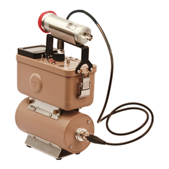
Section 1 Section Introduction he Model 15 is a Neutron Counter coupled to a Model 42-14H Neutron Detector and moderator, as well as a Model 44-7 GM Detector. This combination provides the required electronic circuitry and detectors for measuring and monitoring alpha, beta, and gamma radiation, in addition to fast and slow neutrons (removable moderator for thermal neutrons). -
Page 8: Getting Started
Check individual item serial numbers and ensure calibration certificates match. The Model 15 serial number is located on the front panel below the battery compartment. Most Ludlum Measurements detectors have a label on the base or body of the detector for model and serial number identification. -
Page 9: Battery Installation
Model 15 Technical Manual Section 2 Battery Installation Ensure the Model 15 range selector switch is in the position. Open the battery lid by pushing down and turning the quarter-turn thumbscrew counterclockwise a quarter of a turn. Install two ˝... -
Page 10: Instrument Test
Model 15 Technical Manual Section 2 Instrument Test Connect the GM detector if you have not already done so. Set the switch to . After checking the batteries, turn the instrument range switch to the ×1000 position. Place the switch in the position. -
Page 11: Operational Check
Model 15 Technical Manual Section 2 Operational Check To assure proper operation of the instrument between calibrations and periods of nonuse, an instrument operational check including battery test and instrument test (as described above) should be performed prior to use. -
Page 12: Specifications
Model 15 Technical Manual Section 3 Section Specifications Instrument High Voltage : adjustable independently from 200 to 2500 V; can be read on the meter; electronically regulated to 1%; support of scintillation loads to 1500 V and proportional loads to 2500 V... -
Page 13: Model 42-14H Neutron Detector
Model 15 Technical Manual Section 3 : 99.1 cm (39 in.) with ˝C˝ connector (other available) Cable Model 42-14H Neutron Detector : 2 Atm He tube, LND 25185 or equivalent; Neutron Detector proportional detector with 7.6 cm (3 in.) diameter, cadmium-lined... -
Page 14: Identification Of Controls And Functions
Model 15 Technical Manual Section 4 Section Identification of Controls and Functions : 6.4 cm (2.5 in.) arc, 1 mA analog type with pivot-and-jewel Meter suspension. Typical meter dial is 0-500 cpm, 0-2.5 kV and BAT TEST : used to connect the detector to the instrument. Typically Connector series ˝C,˝... - Page 15 Model 15 Technical Manual Section 4 : This switch allows for selection of the desired detector and is B-G/N associated with the outputs. In the position, the is adjusted for approximately 900 volts for use with GM detectors. In the...
-
Page 16: Safety Considerations
Model 15 Technical Manual Section 5 Section Safety Considerations Environmental Conditions for Normal Use Indoor or outdoor use No maximum altitude Temperature range of -20 to 50 °C (-4 to 122 °F); may be certified for operation from -40 to 65 °C (-40 to 150 °F) -
Page 17: Cleaning And Maintenance Precautions
European Union. Cleaning and Maintenance Precautions The Model 15 instrument and associated detectors may be cleaned externally with a damp cloth, using only water as the wetting agent. Do not immerse the instrument in any liquid. Observe the following precautions when cleaning or performing maintenance on the instrument: 1. -
Page 18: Calibration And Maintenance
Calibration of Discriminator Set the instrument range switch to X10. Remove the calibration cover plate. Connect the Model 15 to the Model 500 Pulser. Set the pulser’s pulse height to 10 ±0.5 mV for use without a GM detector. If a GM detector is used, set the pulse height to 30 ±0.5 mV. -
Page 19: Calibration Of High Voltage Readout
Calibration of High Voltage Readout Open the instrument and locate the calibration control on the main circuit board. Connect the Model 15 to the Model 500 Pulser. Set the B- G/N switch to N. Press the Test switch and record the reading on both the Model 500 and the Model 15. -
Page 20: Efficiency Calibration
Expose the detector to a known neutron field and determine counts/minute per mrem/hr for that energy source. Note that the Model 15 is energy dependent. Repeat the above procedure with the switch in the position and the gamma detector connected and exposed to a known gamma field. -
Page 21: Batteries
Model 15 Technical Manual Section 6 Ludlum Measurements offers a full-service repair and calibration department. We not only repair and calibrate our own instruments but most other manufacturers’ instruments. Calibration procedures are available upon request for customers who choose to calibrate their own instruments. -
Page 22: Troubleshooting
Model 15 Technical Manual Section 7 Section Troubleshooting ccasionally, you may encounter problems with your LMI instrument or detector that may be repaired or resolved in the field, saving turn-around time and expense in returning the instrument to us for repair. Toward that end, LMI electronics technicians offer the following tips for troubleshooting the most common problems. - Page 23 Model 15 Technical Manual Section 7 SYMPTOM POSSIBLE SOLUTION No power (or meter Check battery contacts. Clean them does not reach with rough sandpaper or use an engraver to clean the tips. TEST BAT OK mark) (continued) Check for loose or broken wires, especially between the main board and the high-voltage board.
- Page 24 Model 15 Technical Manual Section 7 SYMPTOM POSSIBLE SOLUTION Meter goes full-scale Ensure that the instrument’s can is or “pegs out” properly attached. When attached (continued) properly, the speaker will be located on the left side of the instrument. If...
-
Page 25: Technical Theory Of Operation
Model 15 Technical Manual Section 8 Section Technical Theory of Operation Input Detector pulses are coupled from the detector through C57 to emitter follower Q96. R83, 89 provide bias. R137 protects Q96 from input shorts. R27 couples the detector to the high-voltage supply. -
Page 26: Digital Analog Converter
Section 8 Digital Analog Converter Pin 12, 15 of U4 are coupled as a current mirror. For each pulse of current through R72, and equal current is delivered to C105. This charge is drained off by R74. The voltage across C105 is proportional to the incoming count rate. -
Page 27: Low Voltage Supply
Model 15 Technical Manual Section 8 Low Voltage Supply Battery voltage is coupled to U7 and associated components (a switching regulator) to provide 5 V at pin 5 to power all logic circuits. Unregulated battery voltage is used to power the meter drive (Q6) and the high voltage blocking oscillator Q145. -
Page 28: Recycling
To this end, Ludlum Measurements, Inc. strives to supply the consumer of its goods with information regarding reuse and recycling of the many different types of materials used in its products. With many different agencies –... -
Page 29: Parts List
Technical Manual Section 10 Section Parts List Reference Description Part Number Model 15 UNIT Completely Assembled Neutron Counter Model 15 Neutron Counter with Detectors With Detectors 48-1614 Main Board, BOARD Completely Assembled Drawing 464 x 655 Main Circuit Board 5464-655 CAPACITORS 0.0047µF, 3kV... - Page 30 Model 15 Technical Manual Section 10 Reference Description Part Number C176 0.0047µF, 3kV 04-5547 C178 0.1µF, 100V 04-5521 C179 0.01µF, 100V 04-5523 TRANSISTORS 2N3904G 05-5755 2N4402BU 05-5763 2N3904G 05-5755 2N3904G 05-5755 Q145 MPSW51AG 05-5765 INTEGRATED CIRCUITS CMXT3904TRLF 05-5890 TLC372 06-6265...
- Page 31 Model 15 Technical Manual Section 10 Reference Description Part Number 8.2k 10-7015 4.7k 10-7014 10-7016 10-7022 10-7019 100 OHM 10-7004 2.2k 10-7012 10-7070 100k 10-7023 10-7016 100k 10-7023 470k 10-7026 2.7 MEG 10-7029 10-7016 R89-R90 100k 10-7023 4.7k 10-7014 R128...
- Page 32 Model 15 Technical Manual Section 10 Reference Description Part Number POTENTIOMETERS 1 MEG, ×1 09-6814 1 MEG, ×10 09-6814 1 MEG, ×100 09-6814 100k, × 1000 09-6813 100k, HV NEUTRON 09-6813 100k, HV BETA/GAMA 09-6813 100k, DISCRIMINATOR (DIS) 09-6813 RESISTORS...
- Page 33 (STD 39 inch) 40-1004 CLIP (44-3 TYPE) W/SCREWS 7002-026-01 CLIP (44-7 TYPE) W/SCREWS 7010-007-01 CLIP (44-6 TYPE) W/SCREWS 7010-008-01 DETECTORS MODEL 44-7 END WINDOW GM PROBE 47-1536 MODEL 15 MODERATOR W/ 42-14H NEUTRON PROBE 47-1575 Ludlum Measurements, Inc. Page 10-5 June 2020...
-
Page 34: Calibration Board, Drawing 363 ×585
Model 15 Technical Manual Section 11 Section Drawings and Diagrams MAIN CIRCUIT BOARD (with Temperature Compensation), Drawing 464 × 655 MAIN CIRCUIT BOARD LAYOUT, Drawing 464 × 658 (2 sheets) CALIBRATION BOARD, Drawing 363 × 585 CALIBRATION BOARD LAYOUT, Drawing 363 × 586 (2 sheets) WIRING DIAGRAM, Drawing 363 ×...
Need help?
Do you have a question about the 15 and is the answer not in the manual?
Questions and answers