Chapters
Table of Contents

Related Manuals for Lunos Silvento


Summary of Contents for Lunos Silvento
- Page 1 Einbauanleitung Silvento Unterputz-Gehäuse 1 und 2-Raum - Bitte an den Nutzer weiterleiten - Installation Manual Silvento Flush-Mounted Housing 1 and 2-Room - Please pass on to user -...
- Page 2 Hinweise Hints Abmessungen Dimensions Einbaubeispiele Installation examples Liefereinheiten Delivery units Montage Assembly Elektrischer Anschluss Elektrical connection Filterwechsel Filter replacement Textteil / Beschreibung Text part / description...
- Page 3 2,25 m ...
- Page 4 45 mm 3/S2 44 mm 323 mm 90,5 mm 12 mm 91 mm 52 mm 3/UP (R) 040125 260 mm 69 mm 44 mm 3/S2 323 mm 12 mm 90,5 mm 91 mm 52 mm 3/UP (A) 040125 260 mm...
- Page 5 53 mm 68,5 mm 49,5 mm 102,5 mm 12 mm 3/UP-BR 039160 260 mm 69 mm 73 mm 102,5 mm 12 mm 3/UP-BA 039179 260 mm...
- Page 6 68,5 mm 53 mm 49,5 mm 102,5 mm 12 mm 64 mm 3/UP-2BR 039187 260 mm 73 mm 69 mm 64 mm 102,5 mm 12 mm 3/UP-2BA 039195 260 mm...
- Page 7 3/UP-BR 3/UP (R) 1/WE 115 3/S2 3/UP (A) 3/UP (R) DN80 DN80 3/UP (R) 8/BS...
- Page 8 040125 3/UP 039160 039179 3/UP-BR 3/UP-BA 039187 039195 3/UP-2BR 3/UP-2BA...
- Page 9 040078 V-EC 039209 039543 3/S2 8/B2 □ 136 mm □ 136 mm 8/BS DN 80...
- Page 10 ...
- Page 11 5.10 5.11 5.12 12 mm 40 mm 6 mm...
- Page 12 5.13 5.14 5.15...
- Page 13 5.16 3/UP 5.17 5.18 „UP“ 5.20 5.19 DN80 2/ZSKA 8/BS...
- Page 14 5/W2...
-
Page 15: Table Of Contents
Einbauanleitung Inhalt: Seite: Zu dieser Anleitung, Sicherheitshinweise, Einsatzbereich, Entsorgen Technische Daten, Hinweise Einbaubeispiele, Versandeinheiten Montage - Winkel und Umlenkung montieren Montage - Gehäuse und elektrischer Anschluss Montage - Ventilatoreinsatz und Designblende Montage - Zweitraumanschluss Elektrischer Anschluss Filterwechsel, Reinigung, Zusatz- und Austauschteile Zu dieser Anleitung ... -
Page 16: Technische Daten, Hinweise
(bei aktiver Feuchteregelung „quasi“-stufenlos zwischen 15 und 60/90* m³/h) * je nach Steuerplatine Jeder Silvento ec kann mit einer Steuerplatine ohne Feuchtesensor oder mit Feuchtesensor kombi- niert werden, jede Steuerplatine ist mit jeweils einem Erweiterungsmodul kombinierbar. Daraus ergeben sich folgende Konfigurationsmöglichkeiten:... -
Page 17: Einbaubeispiele, Versandeinheiten
(„Ausblas nach hinten“) Ausblasöffnung möglich, die nach Zweckmäßigkeit wählbar ist. Bei Brandschutz muss die Schachtwand die geforderte Feuerwiderstandsdauer besitzen! 4 Versandeinheiten Überprüfen Sie die Lieferung auf Vollständigkeit und einwandfreien Zustand! Alle Wandeinbaugehäuse inklusive: Ventilatoreinsatz Silvento V-EC inklusive: Rückschlagklappe Filterrahmen mit Filter ... -
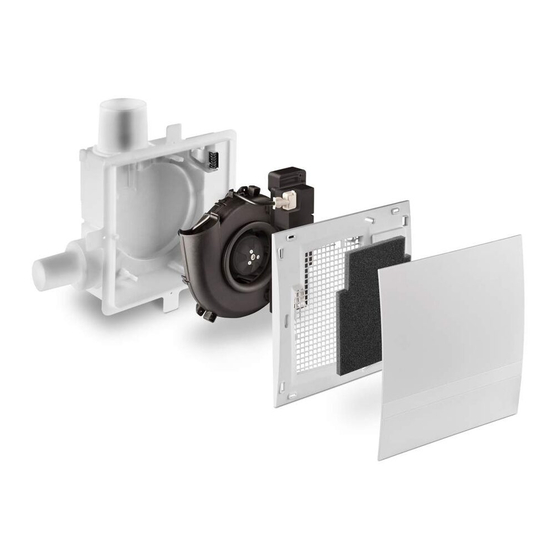
Page 18: Montage - Ventilatoreinsatz Und Designblende
Im Kunststoffgehäuse 5. 5 Stutzen mit Rückschlagklappe durch Verdrehen ausrasten, in Korrekturlage wieder einrasten Im Brandschutzgehäuse Einsatz mit Rückschlagklappe abschrauben, verdrehen, wieder anschrauben ((F) 5.7). Nach erfolgter Korrektur, die Schalldämmung wieder einsetzen! Montagebügel mit beiliegenden Schraubenzubehör am Gehäuse montieren. Befestigen Sie das Gehäuse mit Hilfe der Montagebügel an der Schachtwand. (Schraubenzubehör nicht mitgeliefert) 5.10 Flexrohr anschließen und Verbindung von Flexrohr mit Hauptleitung und Stutzen mit Dicht-... -
Page 19: Montage - Zweitraumanschluss
Zusätzliche Installationen und elektrische Bauelemente im Lüftungsgerät sind unzulässig! Anschlussbilder für weitere Lüfterfunktionen auf Anfrage! Hinweis: Eine Vielzahl von Lüftungsfunktionen des Silvento ec lassen sich über die in der Steuerplatine dieses Typs integrierten DIP-Schalter und über mögliche Zusatzmodule realisieren. Entnehmen Sie bitte diese Informationen der „Einbauanleitung E186 Ventilatoreinsatz Silvento ec“. -
Page 20: Filterwechsel, Reinigung, Zusatz- Und Austauschteile
Je nach Steuerplatine, DIP-Schalterstellung und Modul: Mit Zeitnachlauf (Basisplatine): Deaktivieren der Nachlauffunktionen (L2), Dauerbetrieb Grundlüftung oder AUS entsprechend DIP-Schalter 1 und 2 schaltbar auf Bedarfslüftung (L1) entsprechend DIP-Schalter 6 und 7. Mit Feuchteregelung (Komfortplatine): Deaktivierbare Feuchteregelung (L2), schaltbar auf Bedarfslüftung (L1) Hinweis: Keine Lichtkopplung bei VDE-konformer Installation möglich ((R) Brücke) Je nach Steuerplatine, DIP-Schalterstellung und Modul:... - Page 21 Installation Instructions Contents Page: About These Instructions, Safety Instructions, Range of Application, Disposal Technical Data, Notes Installation Examples, Shipping Units Installing the Angle and Deflection Installation - Housing and Electrical Connection Installation - Fan Insert and Decor Screen Installation - Second Room Connection Electrical Connection Filter Change, Cleaning, Additional Parts and Replacement Parts About These Instructions...
-
Page 22: Technical Data, Notes
(with active humidity control „so to say“-stepless between 15 and 69/90* m³/h) * depending on the control board Every Silvento ec can be combined with a control board without a humidity sensor or with a humidity sensor, each control board can be combined with one extension module. -
Page 23: Installation Examples, Shipping Units
For fire protection, the shaft wall must have the required fire resistance duration! 4 Shipping Units Please check the delivery for completeness and mint condition! All wall installation housings including: Fan insert Silvento V-EC including: Non-return valve Filter frame with filter ... -
Page 24: Installation - Fan Insert And Decor Screen
In plastic housing Disengage the nozzle with non-return valve by turning, re-engage in the correct position In fire protection housing Unscrew insert with non-return valve, turn it, screw it back on. (see Figure 5.7) Reinsert the sound insulation! Use the screw accessories supplied to mount the mounting bracket to the housing. Fasten the housing to the shaft wall using the mounting brackets! (Screw accessories not included) 5.10... -
Page 25: Installation - Second Room Connection
Connection diagrams for further fan functions available on request! Note: A variety of Silvento ec ventilation functions can be created using the DIP switches integrated in the control board of this type and via optional add-on modules. For this information, please refer to the "Fan Insert Silvento ec Installation Manual ". -
Page 26: Filter Change, Cleaning, Additional Parts And Replacement Parts
Depending on the control board, DIP switch position and module: With run-on time (basic control): Deactivation of the run-on functions (L2), conti- nuous operation basic ventilation or OFF according to DIP switches 1 and 2 swit- chable to regulated ventilation (L1) according to DIP switches 6 and 7 With humidity control (comfort control): Humidity control can be deactivated (L2), switchable to regulated ventilation (L1) Note: No light coupling possible with VDE-compliant installation... - Page 27 Notes...
- Page 28 Notes LUNOS Germany LUNOS Lüftungstechnik GmbH Phone +49 30 362 001-0 für Raumluftsysteme +49 30 362 001-89 Wilhelmstr. 31 info@lunos.de 13593 Berlin ∙ Germany www.lunos.de...
Need help?
Do you have a question about the Silvento and is the answer not in the manual?
Questions and answers