Table of Contents
Advertisement
Quick Links
Advertisement
Table of Contents

Subscribe to Our Youtube Channel
Related Manuals for BLAUBERG Ventilatoren Omega Series


Summary of Contents for BLAUBERG Ventilatoren Omega Series
- Page 1 AXIAL FAN Omega USER’S MANUAL...
-
Page 2: Table Of Contents
CONTENTS Delivery set ................................................6 Brief description ..............................................6 Operation guidelines ............................................6 Designation key ..............................................7 Mounting and setup ............................................8 Electronic system operation algorithm ....................................8 Maintenance................................................10 Troubleshooting ..............................................11 Storage and transportation regulations ....................................11 Manufacturer’s warranty ..........................................12 This user’s manual is a main operating document intended for technical, maintenance, and operating staff. - Page 3 FOLLOW THE USER’S MANUAL REQUIREMENTS TO ENSURE DURABLE AND TROUBLE-FREE OPERATION OF THE UNIT. Disconnect the unit from power supply prior to any connection, servicing, maintenance, and repair operations. Only qualified electricians with a work permit for electrical units up to 1000 V are allowed for installation and maintenance. The present user’s manual should be carefully read before beginning works.
- Page 4 internals must be free of any foreign objects that can damage the impeller blades. • While mounting the unit, avoid compression of the casing! Deformation of the casing may result in the motor jam and noisy operation. Misuse of the unit and any unauthorised modifications are not allowed.
- Page 5 • The unit is allowed to be used by children aged from 8 years old and above and persons with reduced physical, sensory, or mental capabilities or no experience and knowledge provided that they have been given supervision or instruction regarding safe use of the unit and understand the risks involved.
-
Page 6: Delivery Set
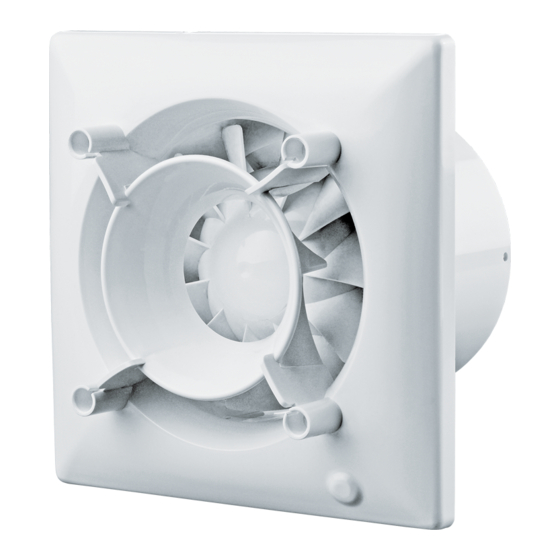
DELIVERY SET Fan - 1 item Screws with dowels - 4 items Plastic screwdriver - 1 item (only for the models with a timer) Operation manual - 1 item Packing box - 1 item BRIEF DESCRIPTION The product is an axial fan for exhaust ventilation of small and medium-sized premises heated in winter. The design of the fan may include a back valve that prevents air from flowing into the room when the fan is off. -
Page 7: Designation Key
DESIGNATION KEY Omega X 100 Power supply parameters _ — 220-240 V/50 Hz by default (220 V/60 Hz) — 220 V/60 Hz Options S: pull cord switch Т: turn-off delay timer ТR: turn-on and turn-off delay timer ST: turn-on/turn-off delay timer and pull cord switch Н: humidity sensor and turn-off delay timer SH: pull cord switch, humidity sensor, and turn-off delay timer Outlet duct diameter [mm]... -
Page 8: Mounting And Setup
MOUNTING AND SETUP The fan can be mounted to the ceiling or onto a wall with air extraction into a ventilation shaft or a matching diameter round air duct (Fig. 2). The fan installation steps are given on Fig. 3-11. Electric connection diagrams are given on Fig. 12-17. Connection diagram terminal key: L —... - Page 9 THE TIMER CIRCUIT IS LIVE. MAKE SURE THE FAN IS DISCONNECTED FROM POWER SUPPLY. The H model fans equipped with a timer and a humidity sensor are activated by control voltage application to input terminal S or on exceeding the pre-set humidity level H adjustable within the ~60 % to ~90 % range. Upon control voltage removal or a decrease of humidity level H the fan continues to operate for the period of time set by the timer within the range from 2 to 30 minutes.
-
Page 10: Maintenance
DO NOT USE A METAL SCREWDRIVER, KNIFE, ETC. FOR ADJUSTMENT OPERATIONS NOT TO DAMAGE THE CIRCUIT BOARD. The fan is supplied with a special plastic screwdriver. Use the screwdriver to adjust the fan activation or deactivation delay or the humidity sensor threshold value. 0 min 2 min for TR... -
Page 11: Troubleshooting
TROUBLESHOOTING Problem Possible reasons Troubleshooting Make sure the power supply line No power supply. is connected correctly, otherwise When the unit is connected to power mains, the fan does not rotate and troubleshoot the connection error. does not respond to any controls. Internal connection fault. -
Page 12: Manufacturer's Warranty
MANUFACTURER’S WARRANTY The product is in compliance with EU norms and standards on low voltage guidelines and electromagnetic compatibility. We hereby declare that the product complies with the provisions of Electromagnetic Compatibility (EMC) Directive 2014/30/ EU of the European Parliament and of the Council, Low Voltage Directive (LVD) 2014/35/EU of the European Parliament and of the Council and CE-marking Council Directive 93/68/EEC. - Page 13 • Redesign or engineering changes to the unit. • Replacement and use of any assemblies, parts and components not approved by the manufacturer. • Unit misuse. • Violation of the unit installation regulations by the user. • Violation of the unit control regulations by the user. •...
- Page 14 [mm] [mm] [mm] [mm] Omega 100 Omega 125 ø D...
- Page 15 CAUTION! The decorative front panel is available separately.
- Page 16 Omega100/125 Omega 100/125 T Omega 100/125 S/ST Omega 100/125 T/ST Fan does not run Contact of S1 switch or pull cord switch is CLOSED Fan runs Contact of S1 switch or pull cord switch is OPENED Activation of turn-off delay timer (2-30 minutes)
- Page 17 Omega 100/125 TR Fan does not run Contact of S1 switch or pull cord switch is CLOSED Activation of turn-off delay timer (0-2 minutes) Switch is OFF during countdown of turn-on delay timer Fan runs Contact of S1 switch or pull cord switch is OPENED Activation of turn-off...
- Page 18 Omega 100/125 H Omega 100/125 SH Fan does not run Contact of S1 switch or pull cord switch is CLOSED Humidity exceeds set point Fan runs Contact of S1 switch or pull cord switch is OPENED Fan runs Humidity is below set point Activation of turn-off...
- Page 19 Omega V2 100/125 TR Fan runs at speed 1 Contact of S1 switch is CLOSED Activation of turn-on delay timer (0-2 minutes) Fan runs at speed 2 Contact of S1 switch is OPENED Activation of turn-off delay timer (2-30 minutes)
- Page 20 Omega V2 100/125 H Fan runs at speed 1 Contact of S1 switch is CLOSED Humidity exceeds set point Activation of turn-on delay timer (45 seconds) The contact of S1 switch is OPENED during turn-on delay timer operation Fan runs at speed 2 Humidity is below set point Fan runs at speed 2 Activation of turn-off...
- Page 21 Omega V2 100/125 speed 1 and 2 Fan does not run Contact of S1 switch is CLOSED S1 switch in position Fan runs at speed 2 Fan runs at speed 1 Contact of S1 switch is OPENED DO NOT CLOSE CONTACTS S AND L WITH EACH OTHER. THIS MAY LEAD TO PRODUCT DAMAGE...
- Page 23 Quality Inspector’s Stamp Seller (name and stamp of the seller) Manufacture Date Purchase Date...
- Page 24 220 V/ Omega V2 60 Hz www.blaubergventilatoren.de B160-2EN-01...
Need help?
Do you have a question about the Omega Series and is the answer not in the manual?
Questions and answers