
Related Manuals for BLAUBERG Ventilatoren Vento Expert A50C3-1 S8 W V.2


Summary of Contents for BLAUBERG Ventilatoren Vento Expert A50C3-1 S8 W V.2
- Page 1 Single-room reverSible energy recovery ventilator vento expert a50c3-1 S8 W v.2 USER’S MANUAL...
-
Page 2: Table Of Contents
The manual contains information about the purpose, technical details, operating principle, design, and installation of the Vento Expert A50C3-1 S8 W V.2 unit (-s) and all of its (their) modifications. Technical and maintenance staff must have theoretical and practical training in the field of ventilation systems and should be able to work in accordance with workplace safety rules as well as construction norms and standards applicable in the territory of the country. - Page 3 S8 W v.2 www.blaubergventilatoren.de • Do not change the power cable length at your own discretion. Do not bend the power • Do not lay the power cable of the unit in cable. Avoid damaging the power cable. Do close proximity to heating equipment.
-
Page 4: Purpose
S8 W v.2 www.blaubergventilatoren.de PURPOSE The ventilator is designed to ensure continuous mechanical air exchange in flats, cottages, hotels, cafés and other domestic and public premises. The ventilator is equipped with a regenerator that enables supply of fresh filtered air heated by means of extract air heat energy recovery. -
Page 5: Technical Data
S8 W v.2 www.blaubergventilatoren.de TECHNICAL DATA The ventilator is rated for indoor application with the ambient temperature ranging from -30 °C up to +40 °C and relative humidity up to 65 %. The unit is rated as a class II electric appliance. -
Page 6: Unit Design And Operating Principle
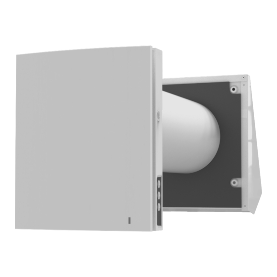
S8 W v.2 www.blaubergventilatoren.de UNIT DESIGN AND OPERATING PRINCIPLE The ventilator consists of an indoor unit with a decorative front panel, a cartridge, an air duct with a sound absorbing layer and an outer ventilation hood. The cartridge is a basic functioning part of the ventilator. The cartridge consists of the fans, the regenerator and two filters that ensure rough air filtration and prevent ingress of dust and foreign objects into the heat exchanger and the fan. - Page 7 S8 W v.2 www.blaubergventilatoren.de VENTILATOR OPERATION MODES Ventilation: the ventilator runs either in air extraction or air supply mode at a set speed. In this mode some of the ventilators in the network run in air supply mode and the other ones in air extraction mode, depending on the position of the DIP switch No.
-
Page 8: Installation And Set-Up
S8 W v.2 www.blaubergventilatoren.de INSTALLATION AND SET-UP READ THE USER'S MANUAL BEFORE INSTALLING THE UNIT. DO NOT BLOCK THE AIR DUCT OF THE INSTALLED VENTILATOR WITH DUST ACCUMULATING MATERIALS, SUCH AS CURTAINS, CLOTH SHUTTERS, ETC. AS IT PREVENTS AIR CIRCULATION IN THE ROOM. - Page 9 S8 W v.2 www.blaubergventilatoren.de 3. Stick the delivered cardboard master plate on the indoor wall using a mounting tape. The large opening in the master plate must be axially aligned with the air duct. For aligning the master plate with respect to the horizon line it is recommended to use a builder’s level.
- Page 10 S8 W v.2 www.blaubergventilatoren.de 7. Install the cartridge into the air duct as figured below. Be sure the pointer is directed upwards. Then fix the wire with the retaining clip and connect the connector to the circuit board.
-
Page 11: Connection To Power Mains And Control
S8 W v.2 www.blaubergventilatoren.de CONNECTION TO POWER MAINS AND CONTROL POWER OFF THE POWER SUPPLY PRIOR TO ANY OPERATIONS WITH THE UNIT. THE UNIT MUST BE CONNECTED TO POWER SUPPLY BY A QUALIFIED ELECTRICIAN. THE RATED ELECTRICAL PARAMETERS OF THE UNIT ARE GIVEN ON THE MANUFACTURER’S LABEL. - Page 12 S8 W v.2 www.blaubergventilatoren.de POSITIONING OF THE DIP SWITCH Ventilator network setup OFF – master unit (hereinafter referred to as “Master unit”) ON – slave unit (hereinafter referred to as “Slave unit”) Standby mode setup OFF – the ventilator is switched off in the Standby mode.
- Page 13 S8 W v.2 www.blaubergventilatoren.de VENTILATOR CONTROL WITH THE BUTTONS ON THE INDOOR UNIT The speed selection sequence is as follows: I-II-III-Standby. All the units integrated in a single network operate according to the speed settings of the Master unit.
- Page 14 S8 W v.2 www.blaubergventilatoren.de REMOTE CONTROL OF THE VENTILATION UNIT ON/Standby. The Standby mode depends on the position of the DIP switch 2 (see page 12). The same button is used to reset alarms (Alarm) and turn off the timers.
- Page 15 S8 W v.2 www.blaubergventilatoren.de VENTILATION UNIT OPERATION WITH THE MOBILE APPLICATION To enable operation of the unit with a mobile device, install a Blauberg Vento V.2 application to your mobile device. Blauberg Vento V.2 - App Store Blauberg Vento V.2 Play Market...
- Page 16 S8 W v.2 www.blaubergventilatoren.de ON/Standby. The Standby mode depends on the position of the DIP switch 2 (see page 12). Selection of the preset speed: Speed I, II and III respectively. Manual speed setup. To activate the scroll bar, check it.
- Page 17 S8 W v.2 www.blaubergventilatoren.de VENTILATOR PASSWORD CHANGE 1. Choose the connection and press the Settings button. 2. Enter and confirm the password. 3. Press the Change Password button To set the Night mode, Party mode timer and the turn-off delay timer for the Boost mode, go to Menu - Settings - Timers in the mobile application.
- Page 18 S8 W v.2 www.blaubergventilatoren.de DATE AND TIME SETUP To set up the weekly schedule in the mobile app, go to Menu -> Settings -> Schedule. The weekly schedule can be set by means of 4 time intervals available for each day of the week.
- Page 19 S8 W v.2 www.blaubergventilatoren.de WIRELESS CONNECTION OF SEVERAL VENTILATION UNITS Master unit via Wi-Fi. The Master unit is operated by means of a mobile device, the remote control or the touch buttons on the unit casing. The control signal is automatically transferred to the connected Slave units. In this mode the unit responds to a signal from sensors (humidity sensor, external digital sensor, external analogue sensor 0-10 V) and changes its operation mode respectively.
- Page 20 S8 W v.2 www.blaubergventilatoren.de VENTILATOR WIRELESS CONNECTION DIAGRAMS In case of connection of 8 Slave units to the Master unit with its own wireless access point, a mobile device may not be connected. Master Wiring diagram 2...
- Page 21 S8 W v.2 www.blaubergventilatoren.de CONNECTING MASTER AND SLAVE VENTILATORS WHILE COMPLETING THE CONNECTION MAKE SURE THAT THE SLAVED VENTILATORS ARE WITHIN WI-FI COVERAGE OF THE MASTER VENTILATOR Press and hold the Ventilation button on the master ventilator casing. Wait for the beep and the blinking of all the LEDs on the...
- Page 22 S8 W v.2 www.blaubergventilatoren.de CLOUD SERVER CONNECTION The ventilators can be controlled using the mobile app via a cloud server connection. This functions enables control of a single or multiple ventilators connected according to Diagram 2 over any distance using the mobile app connected to the Internet.
- Page 23 S8 W v.2 www.blaubergventilatoren.de AIR FLOW CUT-OFF Press the front panel to close the air duct. The fan turns off automatically. The unit functionality is not changed. To open the air duct, pull the front panel while holding the special recesses. The fan starts operating according to the actual speed setting.
-
Page 24: Technical Maintenance
S8 W v.2 www.blaubergventilatoren.de TECHNICAL MAINTENANCE DISCONNECT THE UNIT FROM POWER SUPPLY BEFORE ANY MAINTENANCE OPERATIONS! Maintenance of the ventilator means regular cleaning of the ventilator surfaces of dust and cleaning and replacement of the filters. To enable access to the main units, follow the procedure described below. - Page 25 S8 W v.2 www.blaubergventilatoren.de 3. Pull the cord to remove the cartridge from the air duct. Clean the filters as they get clogged, but not less than once in three months. • Upon elapse of the set time period (factory setting 90 days) the filter replacement indicator (Filter) starts glowing. The filter timer is reset using the program on the mobile device.
-
Page 26: Storage And Transportation Regulations
S8 W v.2 www.blaubergventilatoren.de POSSIBLE REASONS AND TROUBLESHOOTING Problem Possible reasons Troubleshooting Make sure the power supply line is connected No power supply. correctly, otherwise troubleshoot the connection When switching on the error. ventilator, the fan does not Turn the ventilator off. -
Page 27: Manufacturer's Warranty
S8 W v.2 www.blaubergventilatoren.de MANUFACTURER’S WARRANTY The product is in compliance with EU norms and standards on low voltage guidelines and electromagnetic compatibility. We hereby declare that the product complies with the provisions of Electromagnetic Compatibility (EMC) Directive 2014/30/EU of the European Parliament and of the Council, Low Voltage Directive (LVD) 2014/35/EU of the European Parliament and of the Council and CE-marking Council Directive 93/68/EEC. - Page 28 S8 W v.2 www.blaubergventilatoren.de...
- Page 29 S8 W v.2 www.blaubergventilatoren.de...
- Page 30 S8 W v.2 www.blaubergventilatoren.de...
-
Page 31: Certificate Of Acceptance
S8 W v.2 www.blaubergventilatoren.de CERTIFICATE OF ACCEPTANCE Unit Type Single-room reversible energy recovery ventilator Model Vento Expert _________________ Serial Number Manufacture Date Quality Inspector’s Stamp SELLER INFORMATION Seller Address Phone Number E-mail Purchase Date This is to certify acceptance of the complete unit delivery with the user’s manual. The warranty terms are acknowledged and accepted. - Page 32 www.blaubergventilatoren.de B133-6EN-01...
Need help?
Do you have a question about the Vento Expert A50C3-1 S8 W V.2 and is the answer not in the manual?
Questions and answers