
Subscribe to Our Youtube Channel
Related Manuals for Cypress Semiconductor CapSense Express CY3218-CAPEXP2


Summary of Contents for Cypress Semiconductor CapSense Express CY3218-CAPEXP2
- Page 1 CY3218-CAPEXP2 CapSense™ Express Evaluation Kit Quick Start Doc. # 001-44863 Rev. *A Cypress Semiconductor 198 Champion Court San Jose, CA 95134-1709 Phone (USA): 800.858.1810 Phone (Intnl): 408.943.2600 http://www.cypress.com...
-
Page 2: Getting Started
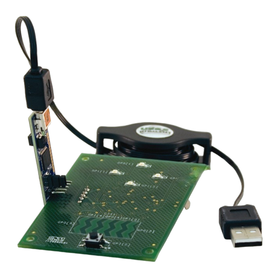
Getting Started 1. Review Kit Contents 2. Explore the Board 3. Install Software 4. CY3218-CAPEXP2 Board Features 5. Tune the CY3218-CAPEXP2 CapSense Express Board 6. Create a CY3218-CAPEXP2 CapSense Express Project 7. Additional CapSense Resources 1. Review Kit Contents Each CY3218-CAPEXP2 CapSense Express Demonstration Kit contains: CY3218-CAPEXP2 CapSense Express Demonstration Board ■... -
Page 3: Install Software
3. Install Software Install PSoC Express Development Software 3.1. Insert the Kit CD, wait for the installer to start, and install the following software in the order listed: Install PSoC Programmer. Install .NET Framework 2.0. Install PSoC Express 3. Install CapSense Express Extension Pack. Install CapSense Express Kit Documentation. - Page 4 5. Tune the CY3218-CAPEXP2 CapSense Express Board Functional Description When a finger moves along the capacitive slider, corresponding LEDs are lit in a circular pro- gression. Additionally, pressing the pushbutton switch causes all of the LEDs to be lit. Tuning Steps 5.1.
- Page 5 5.3. From the Express Design Catalog, open the CY3218 CAPEXP2 CapSense Express Kit folder. 5.4. Double-click 5 Segment CapSense Slider to open the design. 5.5. Name the design FiveSegmentSlider and save the design in the location of your choice. 5.6. Click Monitor to open the Monitor view. 5.7.
- Page 6 5.10. Test the board by moving your finger across the slider. The LEDs above the slider turn on each time the corresponding slider segment is touched. Press the mechanical button at the bottom of the board to turn on all four LEDs. Notice how the Pin Status and Latched Value indicators change from OFF to ON when a slider segment is touched.
- Page 7 5.14. Slide your finger across the slider. Notice the difference bars above the green position bar. Also notice how the LEDs illuminate in a clockwise direction as you move your finger from the left to the right across the slider. 5.15.
- Page 8 5.16. Change the IDAC setting for each segment from 14 to 5, and click Apply to board.’ 5.17. Cover the slider with the paper again, and touch the slider. The difference bars are now higher. If the LEDs do not light, keep adjusting the IDAC settings lower until the LEDs light reliably.
- Page 9 6. Create a CY3218-CAPEXP2 CapSense Express Project Start the Project 6.1. Connect your computer to the CapSense test board I C Connector (J5) using the CY3240-I2USB Bridge Board and a USB cable. When connected correctly, the USB con- nector on the CY3240-I2USB Bridge Board is visible when viewing the front of the CY3218-CAPEXP2 board.
- Page 10 6.7. Name the driver Slider and click OK. The CapSense Express 5 Segment / Slider 5 GPIO : Slider window opens. In PSoC Express, each CapSense slider, LED, and mechanical button requires a separate driver. The 5 Segment Slider 5 GPIO driver is a special driver that allows you to configure the slider, LED, and mechanical button in one interface.
- Page 11 Configure the Drivers 6.8. By default, all driver types in the Configure Local Parameters pane are set to CapSense Slider Sensor. To setup the LEDs, set the Pin Type for drivers C0 through C3 to GPOutput and the Drive Mode for each of those drivers to Strong Drive. To setup the mechanical button, set the Pin Type for driver G4 to GPInput.
- Page 12 6.10. To assign an LED to a CapSense slider segment, simply click on the yellow box of the CapSense slider segment you want to assign to LED G0. For LED driver G0, select the CapSense slider segment Sldr0. A small line will then connect C0 to the purple OR box. To have the LED turn on when the slider segment is touched, click the little box to the right of the purple OR box.
- Page 13 6.11. Since there are four LEDs and five slider segments, have the LED G0 turn on when the first and last slider segments are touched. To do this, simply click on the yellow Sldr4 box. Invert Symbol Default = LED Off Connecting Line 6.12.
- Page 14 6.13. To assign the rest of the slider segments to the other LEDs, simply select each LED from the Select Pin menu, and click on the appropriate slider segment, and the G4 mechanical button. Remember to click the square box so the invert symbol is showing. Control the LEDs with the slider segments mechanical button according to the following table: Control Sldr0, Sldr4, &...
- Page 15 6.16. Assign each CapSense slider segment, LED, and mechanical button to the pin annotated on the board. For example, the leftmost slider segment, Sldr1, is labeled GP0[3]. GP1[4] GP0[4] GP1[3] GP0[3] GP0[2] Drag each driver from the Unassigned list to the appropriate pin (listed on page 16 for con- venience).
- Page 16 Driver Sldr1 (Sldr0) GP0[4] Sldr2 (Sldr1) GP0[3] Sldr3 (Sldr2) GP0[2] Sldr4 (Sldr3) GP1[4] Sldr5 (Sldr4) GP1[3] Output1 (G0) GP0[1] Output2 (G1) GP0[0] Output3 (G2) GP1[0] Output4 (G3) GP1[1] Input1 (G4) GP1[2] 6.17. Click OK to close the User Pin Assignment window. 6.18.
- Page 17 6.22. In the Pin Specific Tuning pane, check Show Differences. 6.23. Slowly move your finger from left to right across the slider. The LEDs light clockwise start- ing with the topmost LED on the board. 6.24. Press the mechanical button. All LEDs light at the same time. What’s Next Congratulations! You have successfully recreated the factory installed program used in Section 5.
- Page 18 7. Additional CapSense Resources PSoC Data Sheets, Application Notes and Technical Articles Cypress provides a wealth of information about CapSense Express, and more is frequently added. Many sample documents, schematics, layouts, guidelines, and other CapSense Express documents are available on the CD and at www.cypress.com (except where indicated).
- Page 19 CapSense Technical Articles Designer's Guide to Rapid Prototyping of Capacitive Sensors on any Surface ■ Controls & Sensors Touch Sensors Spread Out ■ White Paper Cypress’s CapSense Successive Approximation Algorithm ■ The Art of Capacitive Touch Sensing ■ Design Support PSoC Development Software Online All PSoC development software tools are available for download online.
- Page 20 For more information on these kits, please go to www.cypress.com/CapSense. CapSense™, PSoC Designer™, Programmable System-on-Chip™, and PSoC Express™ are trademarks and PSoC® is a registered trademark of Cypress Semiconductor Corp. All other trademarks or registered trademarks referenced herein are property of the respective corporations.
Need help?
Do you have a question about the CapSense Express CY3218-CAPEXP2 and is the answer not in the manual?
Questions and answers