
Related Manuals for Cypress Semiconductor FM4 S6E2 Series


Summary of Contents for Cypress Semiconductor FM4 S6E2 Series
- Page 1 FM4 S6E2G-Series Pioneer Kit Guide Doc. # 002-10541 Rev. *F Cypress Semiconductor 198 Champion Court San Jose, CA 95134-1709 www.cypress.com...
- Page 2 Copyrights © Cypress Semiconductor Corporation, 2015-2017. This document is the property of Cypress Semiconductor Corporation and its subsidiaries, including Spansion LLC (“Cypress”). This document, including any software or firmware included or referenced in this document (“Software”), is owned by Cypress under the intellectual property laws and treaties of the United States and other countries worldwide.
-
Page 3: Table Of Contents
Contents Introduction ..................................4 Kit Contents ................................5 Board Details ................................. 6 Jumpers and Connectors ............................7 Getting Started ..............................8 Additional Learning Resources ..........................8 Technical Support ..............................8 Acronyms................................9 Installation and Test Operation ..........................10 Install Software ..............................10 Uninstall Software .............................. -
Page 4: Introduction
1. Introduction Thank you for your interest in the FM4-176L-S6E2GM FM4 S6E2G-Series Pioneer Kit. The FM4 S6E2G-Series Pioneer Kit enables customers to evaluate and develop projects using the FM4 device family. Flexible MCU 4 (FM4) is a portfolio of ® ®... -
Page 5: Kit Contents
Introduction 1.1 Kit Contents The FM4 S6E2G-Series Pioneer Kit contains the following, as shown in Figure 1-1. FM4 S6E2G-Series Pioneer board USB Standard-A to Micro-B cable Quick Start Guide Figure 1-1. Kit Contents Inspect the contents of the kit; if you find any part missing, contact your nearest Cypress sales office for help: www.cypress.com/support. -
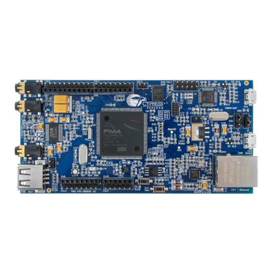
Page 6: Board Details
Introduction 1.2 Board Details Figure 1-2. FM4 S6E2G-Series Pioneer Kit Markup FM4 S6E2G-Series Pioneer Kit Guide, Doc. # 002-10541 Rev. *F... -
Page 7: Jumpers And Connectors
Introduction 1.3 Jumpers and Connectors Table 1-1. Jumper Description Jumper Function Setting Open: User mode Sets the programming mode of MB9AF312K (CMSIS-DAP) Closed: Serial programming mode Open: User mode Sets the programming mode of S6E2GM Closed: Serial programming mode Pin 2 to Pin 1: UART programming mode via UART0 Sets the serial programming connected to MB9AF312K mode for the S6E2GM... -
Page 8: Getting Started
Introduction 1.4 Getting Started This guide will help you get started with the FM4 S6E2G-Series Pioneer Kit: Installation and Test Operation chapter describes the installation of the kit, and the test procedures for testing the board. Hardware chapter describes the major features of the FM4 S6E2G-Series Pioneer Kit and functionalities such as CMSIS-DAP debugger, Ethernet, USB, stereo codec, memories and sensors. -
Page 9: Acronyms
Introduction 1.7 Acronyms Table 1-3. Acronyms Used in this Document Acronym Description Analog-to-Digital Converter Controlled Acess Network CMSIS-DAP Debug Access Port GPIO General Purpose Input/Output Inter-Integrated Circuit Inter-IC Sound Integrated Development Environment Internet of Things JTAG Joint Test Action Group Low Drop Out (voltage regulator) Light-Emitting Diode Local Interconnect Network... -
Page 10: Installation And Test Operation
2. Installation and Test Operation This chapter describes the steps to install the software tools and drivers on a PC for using the FM4 S6E2G-Series Pioneer Kit. After the successful installation, the user can run the test demo code that was pre-programmed in the device. 2.1 Install Software Follow these steps to install the FM4 S6E2G-Series Pioneer Kit software: Download the FM4 S6E2G-Series Pioneer Kit installer from the web page... - Page 11 Installation and Test Operation Click Install FM4 S6E2GM Kit to start the kit installation, shown in Figure 2-1. Figure 2-1. Kit Installation Window Select the default installation folder, or click Browse to select a different folder, and click Next. Select the Installation Type (see Figure 2-2).
- Page 12 Installation and Test Operation After you click Next, the installation begins, a list of packages appears on the Installation page. A Green check mark appears next to each package after successful installation. Following are the required software and driver: FM Universal Peripheral Driver Library (PDL) ...
- Page 13 Installation and Test Operation Click Install. Figure 2-4. Extract the Example Projects Figure 2-5. Extract FM PDL 2.0 10. Click Close to complete the extraction. After the installation is complete, kit documentation and hardware files are available at the following default location: Windows OS (64-bit): C:\Program Files (x86)\Cypress \FM4 S6E2G-Series Pioneer Kit Windows OS (32-bit): C:\Program Files\Cypress...
-
Page 14: Uninstall Software
Installation and Test Operation And, the example projects will be extracted to the following default directory: C:\Users\<User Name>\My Documents\Cypress \FM4 S6E2G-Series Pioneer Kit_Ver01\Firmware In the rest of the document, the following directory is termed as <User_Directory>: C:\Users\<User Name>\My Documents\Cypress 2.2 Uninstall Software The software can be uninstalled using one of the following methods: ... - Page 15 Installation and Test Operation Ensure the power LED (LED3) is ON. Launch the Serial Port Viewer Tool from Start > All Programs > Cypress > Serial Port Viewer Tool. Click on the Serial Port Viewer icon in the task bar and select FM-Link/CMSIS-DAP Cypress FM Communications Port. Figure 2-7.
- Page 16 Installation and Test Operation For example, key in 8 and press the [Enter] key. Figure 2-10. USB Host Test-1 Insert a USB device into the USB Type-A connector (CN14). Once the USB device is detected, Device is CONNECTED will be displayed in the terminal as shown in Figure 2-11.
- Page 17 Installation and Test Operation 12. Figure 2-12. Press [Enter] to return to the main menu. FM4 S6E2G-Series Pioneer Kit Guide, Doc. # 002-10541 Rev. *F...
- Page 18 Installation and Test Operation Figure 2-12. USB Host Test-3 2.3.2 Test Procedure Explanation This section explains the test procedure. This test procedure is based on the Serial Port Viewer Tool. The user has to key-in the test procedure number displayed on the menu and then press the [Enter] key on the PC. The firmware on the board will run the test procedure and display the results.
- Page 19 Installation and Test Operation Figure 2-14. NOR Flash Test SRAM Test: This procedure tests the SRAM. Key in 3 and press the [Enter] key. The code will write a pre-determined set of data into the SRAM and then will read and compare to check whether the data is the same. If it is the same, then it will display OK, otherwise it will display Fail.
- Page 20 Installation and Test Operation RGB LED Test: This procedure tests the RGB LED (LED4). Key in 5 and press the [Enter] key. The RGB LED (LED4) color will change from Red to Green to Blue. The sequence will repeat until you press the [Enter] key to return to the main menu.
- Page 21 Installation and Test Operation USB Host Test: This procedure tests the USB host circuitry. Key in 8 and press the [Enter] key. A message indicating that the Device is CONNECTED will be displayed on the terminal if a USB device is connected to the USB Type-A connector (CN14).
- Page 22 Installation and Test Operation Note: Please connect a stereo microphone to CN11 and a headphone to CN5. A microphone integrated with a headphone will not work properly for this demonstration. I2S Line-in Test: This procedure is to test the line-in channel of the stereo codec. Connect CN6 to the line-out jack of computer using an audio cable, connect a headphone to CN5.
-
Page 23: Hardware
3. Hardware This chapter describes the features and hardware details of the FM4 S6E2G-Series Pioneer Kit. 3.1 System Block Diagram Figure 3-1 shows the system block diagram of the FM4 S6E2G-Series Pioneer Kit. Figure 3-1. System Block Diagram FM4 S6E2G-Series Pioneer Kit Guide, Doc. # 002-10541 Rev. *F... -
Page 24: Hardware Features
Hardware 3.2 Hardware Features Cypress FM4 S6E2GM MCU On-board ICE (CMSIS-DAP compatible) 10-pin JTAG interface Ethernet PHY and RJ45 connector (IEEE802.3) USB device interface USB host interface 32Mb NOR flash 4Mb external SRAM ... - Page 25 Hardware The port P1A/PB2/P18 pins are also assigned as PWM output pins, the user can dim the LED by configuring the base timers in PWM mode to output PWM signals from the pins (i.e. TIOA4_2, TIOA10_1, and TIOA3_2). 3.3.3 Arduino Compatible Interface The FM4 S6E2G-Series Pioneer Kit provides footprint compatibility with the Arduino interface.
- Page 26 Hardware Table 3-2 shows full functions of the pins connected with the Arduino headers. Table 3-2. Pins of Arduino Compatible Interface Pin No. Pin Name Arduino Designation Function (Part) UART – RX PF5/SIN3_1/IC11_1/TIOB7_1/INT07_1/IC1_RST_1 UART – TX PF6/SOT3_1/IC12_1/TIOA14_1/INT20_1/IC1_DATA_1 PF7/SCK3_1/IC13_1/TIOB14_1/INT21_1/IC1_CIN_1 P43/SCS70_1/RTO13_0/TIOA3_0/INT04_0/MCSX4_0 PF4/IC10_1/TIOA7_1/INT06_1/IC1_VPEN_1 P44/SCS71_1/RTO14_0/TIOA4_0/MCSX3_0 P45/SCS72_1/RTO15_0/TIOA5_0/MCSX2_0 PF3/SCS63_0/FRCK1_1/TIOB6_1/INT05_1/IC1_VCC_1...
- Page 27 Hardware 3.3.4 Additional GPIO Headers The unused pins of the S6E2GM MCU are routed to the CN15, CN16, CN17, and CN18 I/O headers. Figure 3-3. Additional GPIO Pins These additional GPIO headers make it easy for the user to access more GPIOs and peripherals, such as the MFS (Multi-Function Serial), PWM and I2S.
- Page 28 Hardware Pin No. Pin Name Designation Functions (part) P71/ADTG_8/SIN9_0/INT04_1/MRDY_0 CN15-10 CN18-6 CN18-5 P95/RTS5_1/RTO15_1/TIOB5_1/IC0_CIN_1 CN18-4 P94/CTS5_1/RTO14_1/TIOB4_1/IC0_DATA_1 CN18-3 CN18-2 CN18-1 CN16-1 CN16-2 CN16-3 P1C/AN12/SCK0_1/TIOA5_2/TRACECLK CN16-4 ADC, PWM PB4/AN20/SCS63_1/TIOA11_1/INT10_1/TRACED12 CN16-5 ADC, PWM, INT P1B/AN11/TIOB4_2/INT11_0/TRACED7 CN16-6 ADC, INT PB3/AN19/SCS62_1/TIOB10_1/ZIN0_2/TRACED11 CN16-7 P10/AN00/TIOA0_2/INT08_0/MNREX_0/IC1_CLK_0 CN16-8 ADC, PWM, INT 3.3.5 Stereo Codec WM8731 is a low power stereo codec with an integrated headphone driver.
- Page 29 Hardware Figure 3-4. Stereo Codec Circuit FM4 S6E2G-Series Pioneer Kit Guide, Doc. # 002-10541 Rev. *F...
- Page 30 Hardware 3.3.6 SRAM The CY62147EV30 is a high performance CMOS Static RAM (SRAM) organized as 256K words of 16 bits each. This device uses advanced circuit design to provide ultra-low active current. This device also has an automatic power down feature that significantly reduces the power consumption when addresses are not toggling.
- Page 31 Hardware 3.3.7 NOR Flash The S25FL132K non-volatile flash memory device connects to the S6E2GM device via a Serial Peripheral Interface (SPI). The NOR Flash supports SPI single bit serial input and output (single I/O or SIO) as well as optional two bit (Dual I/O or DIO) and four bit (Quad I/O or QIO) serial protocols.
- Page 32 Hardware 3.3.8 Ethernet MAC The Ethernet MAC of the FM4 S6E2GM MCU is connected to an Ethernet circuit consisting of a PHY and an RJ45 connector to enable full Ethernet application development. The KSZ8091 is a single-supply 10Base-T/100Base-TX Ethernet PHY for transmission and reception of data over standard CAT-5 unshielded twisted pair cable.
- Page 33 Hardware 3.3.9 Multicon I/F The Multicon interface, CN12, is a 2x5 pin connector interface that brings the appropriate signals for UART, SPI, I2C and external interrupts. A simple 10-pin cable can be used to route the serial signals and power to a secondary board or another system.
- Page 34 Hardware 3.3.10 Accelerometer The KXCJK-1013 is a 3-axis ±2g, ±4g or ±8g silicon micro-machined accelerometer. This sensor communicates with the MCUs via an I2C interface. The I2C address for the accelerometer is 0x0E. The accelerometer can also interrupt the FM4 S6E2GM MCU when a change is detected in either of the three axes.
- Page 35 Hardware 3.3.12 USB Interfaces The FM4 S6E2GM MCU has two USB channels that can work as a host or a device. In the FM4 S6E2G-Series Pioneer Kit, USB0 is configured as a USB device and is connected to CN3, and USB1 is configured as a USB host and is connected to CN14.
- Page 36 Hardware 3.3.13 CMSIS-DAP The FM4 S6E2G-Series Pioneer Kit features an on-board CMSIS-DAP module to enable programming and debugging of the FM4 S6E2GM MCU. The CMSIS-DAP firmware solution supports a full JTAG configuration and a two-wire Serial Wire Debug (SWD) interface. The CMSIS-DAP module can also power the FM4 S6E2G-Series Pioneer kit via the CN2 connector when jumper J4 is set to short pins 1 and 2.
-
Page 37: Software Development
4. Software Development 4.1 Tool Options The FM4 S6E2G-Series device is supported by several 3rd party tools, and the user can select their preferred tool. The example projects can be opened and compiled in the following two IDEs: IAR Embedded Workbench for ARM ®... - Page 38 Software Development Click File > Open > Workspace and select the workspace file s6e2gm_adc.eww from <User_Directory>:\FM4 S6E2G-Series Pioneer Kit_Ver01\Firmware\Demo Projects\s6e2gm_adc\IAR. FM4 S6E2G-Series Pioneer Kit Guide, Doc. # 002-10541 Rev. *F...
- Page 39 Software Development Click Project > Rebuild All to build the project. Ensure the jumpers on the FM4 S6E2G-Series Pioneer board are placed according to Table 4-1. Table 4-1. Debugging Jumper Settings Jumper Position Description Open Sets MB9AF312K (CMSIS-DAP) in run mode. Open Sets S6E2GM in run mode.
- Page 40 Software Development 4.1.2 Build an Example Project with Keil µVision IDE The following steps describe how to open, build, and run an example project in the Keil µVision IDE: Before doing this, check the availability of the flash loader file of the S6E2GM device (S6E2GMXXA1024KB.FLM) in this directory: <Keil_Install_Directory>:\ARM\Flash.
- Page 41 Software Development Click the Build icon to build the project. Ensure that the jumpers on the FM4 S6E2G-Series Pioneer board are placed according to Table 4-2. Table 4-2: Debugging Jumper Settings Jumper Position Description Open Sets the MB9AF312K (CMSIS-DAP) in run mode. Open Sets the S6E2GM in run mode.
-
Page 42: Example Projects
Software Development 4.2 Example Projects The FM4 S6E2G-Series Pioneer Kit includes twenty one example projects to help the user get a quick start with the S6E2GM device. The example projects are available in the following directory: <User_Directory>:\FM4 S6E2G-Series Pioneer Kit_Ver01\Firmware\Demo Projects The example projects listed in Table 4-3 are based on the Peripheral Driver Library (PDL). - Page 43 Software Development Projects Title/Description Title: Multi-function Serial Interface Description: This project demonstrates the UART communication of the S6E2GM device. This program s6e2gm_mfs_uart enables the MFS0 as a UART to communicate with the CMSIS-DAP device. The CMSIS-DAP device serves as a UART to USB bridge between the MCU and the PC. Refer to UART Communication details.
- Page 44 Software Development Projects Title/Description Title: Audio I2S Line Description: This project demonstrates the operation of the S6E2GM audio codec Line. The project will demonstrate a function that starts or stops Line function through pressing the SW2. When starting s6e2gm_I2S_line the Line function, if playing music with PC, you will hear the music through the headphone. When stopping the Line function, if playing music with PC, you will not hear the music through the headphone.
- Page 45 Software Development 4.2.1 Analog-to-Digital Converter 4.2.1.1 Project Description This project demonstrates the ADC conversion of the S6E2GM device. The project enables ADC channel AN17 to measure the voltage from the phototransistor output. It is converted to a decimal value and sent out using UART0. 4.2.1.2 Hardware Connection No specific hardware connections are required for this project.
- Page 46 Software Development Figure 4-2. ADC value Place your hand over the board to block some light from the phototransistor. Observe the values change in the Serial Port Viewer. 4.2.2 Direct Memory Access DMA) 4.2.2.1 Project Description This project demonstrates the DMA operation of the S6E2GM device. The program configures the DMA to move the data from the au32SourceData (source array) to the au32DestinationData (destination array), and then compares the content of the arrays to verify the data.
- Page 47 Software Development Open Watch1 window from View > Watch. Add the arrays au32SourceData and au32DestinationData in Watch1 window. Run the program for a while (>10 seconds). Stop the program and check the arrays mentioned above. The Program Counter (PC) will stop at the routine as shown below which means the content of the arrays are the same.
- Page 48 Software Development Open Watch1 window from View > Watch Windows. Add the arrays au32SourceData and au32DestinationData in Watch1 window. Run the program for a while (>10 seconds). Stop the program and check the arrays mentioned above. The Program Counter (PC) will stop at the routine as shown below which means the content of the arrays are the same.
- Page 49 Software Development 4.2.3 Flash Write 4.2.3.1 Project Description This project demonstrates the flash writing operation of the S6E2GM device. Four data values (0x00112233, 0x44556677, 0x8899aabb, 0xccddeeff) will be written starting at the 0x00406000 address in flash. 4.2.3.2 Hardware Connection No specific hardware connections are required for this project. All connections are hardwired on the board. 4.2.3.3 Verify Output 4.2.3.3.1 Using IAR Embedded Workbench Power the FM4 S6E2G-Series Pioneer board from CN2 using a USB cable, refer to...
- Page 50 Software Development 4.2.3.3.2 Using Keil µVision IDE Power the FM4 S6E2G-Series Pioneer board from CN2 using a USB cable, refer to Figure 2-6. Open the project s6e2gm_flash in the Keil µVision IDE from the following directory: Keil project: <User_Directory>: \FM4 S6E2G-Series Pioneer Kit_Ver01\Firmware \Demo Projects\s6e2gm_flash\ARM\s6e2gm_flash.uvprojx Build the project and download the code into the S6E2GM device using the debugger.
- Page 51 Software Development 4.2.4 UART Communication 4.2.4.1 Project Description This project demonstrates the UART communication of the S6E2GM device. This program enables the MFS0 as a UART to communicate with the CMSIS-DAP device. The CMSIS-DAP device serves as a UART to USB Bridge between the MCU and the PC.
- Page 52 Software Development Click the Toggle icon to toggle the Outgoing Data Window. Figure 4-4. Toggle the Output Data Window Key in any characters in the Outgoing Data Window, the same characters will be echoed in the Input Data Window. Figure 4-5. Echo Test FM4 S6E2G-Series Pioneer Kit Guide, Doc.
- Page 53 Software Development 4.2.5 Sleep Mode 4.2.5.1 Project Description This project demonstrates the sleep mode operation of the S6E2GM device. The MCU will enter into the sleep mode after blinking the Green LED 5 times. After it is asleep, the device is woken up by pressing SW2 key. After wakeup, the Green LED will turn on.
- Page 54 Software Development 4.2.6 Software Watchdog 4.2.6.1 Project Description This project demonstrates the operation of the S6E2GM watchdog. The project will demonstrate the impact of two different watchdog situations: when the watchdog is fed and when the watchdog is not fed. If the watchdog is enabled, but the watchdog is fed in time, the program will run properly, and the RGB LED (LED4) will blink Green.
- Page 55 Software Development 4.2.7 Audio I2S Headphone 4.2.7.1 Project Description This project demonstrates the operation of the S6E2GM audio codec I2S headphone. The project will demonstrate a function connecting a headphone to the headphone jack to hear a repeated tone. 4.2.7.2 Hardware Connection In this project, you only need to connect a headphone to the headphone jack CN5.
- Page 56 Software Development 4.2.9 Audio I2S Line 4.2.9.1 Project Description This project demonstrates the operation of the S6E2GM audio codec I2S Line. The project will demonstrate a function that starts or stops Line function through pressing the SW2. When starting the Line function, if playing music with PC, you will hear the music through the headphone.
- Page 57 Software Development 4.2.10 USB Device 4.2.10.1 Project Description This example demonstrates the USB peripheral operation as an HID mouse device. The MCU of Gaia start kit includes two USB channels; the board uses the USB0 as device interface. This example sets the endpoint0 of the USB0 as control endpoint, and sets the endpoint1 as the HID mouse data input endpoint.
- Page 58 Software Development 4.2.11 USB Host 4.2.11.1 Project Description This example demonstrates how the USB host reads and writes a USB flash drive. The MCU of FM4 S6E2G-Series Pioneer Board Kit includes two USB channels; the board uses the USB1 as host interface. This example implements the USB mass storage class.
- Page 59 Software Development 4.2.12 NOR Flash 4.2.12.1 Project Description This example shows the usage of an external flash (S25FL132K NOR flash) for data storage controlled by the MCU using SPI interface CSIO. The test performs the following actions once on startup: Read the device ID Sector Erase Page Write...
- Page 60 Software Development 4.2.13 SRAM Operation 4.2.13.1 Project Description This project demonstrates how to set the EXTIF use for write and read function of external SRAM CY62147EV30 on the S6E2GM, and how to set EXTIF 16-bit data width, and 20-bit address bus. The CY62147EV30 is a high performance CMOS static RAM (SRAM) organized as 256K words by 16 bits (4-Mbit).
- Page 61 Software Development 4.2.13.3.2 Using Keil µVision IDE Power the FM4 S6E2G-Series Pioneer board from CN2 using a USB cable, refer to Figure 2-6. Open the project s6e2gm_flash in the Keil µVision IDE from the following directory: Keil project: <User_Directory>: \FM4 S6E2G-Series Pioneer Kit_Ver01\Firmware \Demo Projects\s6e2gm_sram\ARM\s6e2gm_sram.uvprojx Build the project and download the code into the S6E2GM device using the debugger.
- Page 62 Software Development 4.2.14 Accelerometer Operation 4.2.14.1 Project Description This example project demonstrates the usage of accelerometer sensor module; the data of each of axes (X, Y, Z) of the board position will be output to Cypress Serial Port Viewer respectively. This data will change if there is any change of board position.
- Page 63 Software Development Run the program. The data of each of axes (X, Y, Z) of the board position will be output to Cypress Serial Port Viewer respectively. FM4 S6E2G-Series Pioneer Kit Guide, Doc. # 002-10541 Rev. *F...
- Page 64 Software Development 4.2.15 Ethernet Converter 4.2.15.1 Project Description This project demonstrates the Ethernet-MAC function of the S6E2GM device. The PHY layer uses KSZ8091MNX chip, the TCP/IP layer uses LwIP. When ping the board, it will receive the ping-reply. 4.2.15.2 Hardware Connection Connect CN4 to PC network interface via Ethernet cable.
- Page 65 Software Development Ping the board and observe the reply. FM4 S6E2G-Series Pioneer Kit Guide, Doc. # 002-10541 Rev. *F...
-
Page 66: Flash Programming
Software Development 4.3 Flash Programming Most IDEs, including IAR and Keil µVision, are capable of programming the embedded flash. If that option is not desirable for some reason, the following section shows you how to program the embedded flash using either a serial or a USB connection. - Page 67 Software Development 10. Click the Full Operation (D+E+B+P) button to start programming. 11. Reset the S6E2GM by pressing the reset button (SW1) on the board, and click OK. Note: Click on Help for any issues or errors encountered during programming. 4.3.2 Programming the S6E2GM MCU using the FLASH MCU Programmer This method will program using the USB connection to the CMSIS-DAP device which then acts as a USB-UART bridge to the S6E2GM serial interface.
- Page 68 Software Development Launch the FLASH MCU Programmer from Start Menu > All Programs > Cypress > FLASH MCU Programmer > FM0+FM3FM4. Select Target MCU to S6E2GM8H/J. Select Crystal Frequency to 4 MHz. Select the Motorola-S format file or Intel-HEX format file to be programmed to the FLASH memory in the MCU. Note: The hex file selected in this example is the Test Demo firmware.
- Page 69 Software Development 12. Reset the S6E2GM by pressing the reset button (SW1) on the board, and click OK. Note: Click on Help for any issues or errors encountered during programming. 4.3.3 Programming the CMSIS-DAP Device using the FLASH USBDIRECT Programmer By default, the latest CMSIS-DAP firmware is programmed on the MB9AF312K.
- Page 70 Software Development Launch the FLASH USB DIRECT Programmer from Windows Start Menu > All Programs > Cypress > FLASH USB DIRECT Programmer > USBDirect. Set Target MCU to MB9AF312K. Select the Motorola-S format file or Intel-HEX format file to be programmed into the FLASH memory in the MCU. The hex file is included in following directory: <User_Directory>: \FM4 S6E2G-Series Pioneer Kit_Ver01\Firmware\CMSIS-DAP...
- Page 71 Software Development Note: Click on Help for any issues or errors encountered during programming. FM4 S6E2G-Series Pioneer Kit Guide, Doc. # 002-10541 Rev. *F...
-
Page 72: Appendix
A. Appendix Schematic Figure A-1. MCU FM4 S6E2G-Series Pioneer Kit Guide, Doc. # 002-10541 Rev. *F... - Page 73 Appendix Figure A-2. CMSIS-DAP and USB FM4 S6E2G-Series Pioneer Kit Guide, Doc. # 002-10541 Rev. *F...
- Page 74 Appendix Figure A-3. Ethernet FM4 S6E2G-Series Pioneer Kit Guide, Doc. # 002-10541 Rev. *F...
- Page 75 Appendix Figure A-4. Stereo Codec FM4 S6E2G-Series Pioneer Kit Guide, Doc. # 002-10541 Rev. *F...
- Page 76 Appendix Figure A- 5. Memory, Sensor and Interfaces FM4 S6E2G-Series Pioneer Kit Guide, Doc. # 002-10541 Rev. *F...
-
Page 77: Bill Of Materials
Appendix Bill of Materials Item Reference Value Description Mfg Part Number C1, C2, C3, C5, C6, C9, C10, C13, C15, C16, C17, C22, C24, C25, C26, C29, C39, C43, C49, C50, C52, 0.1uF Ceramic Capacitor YAGEO CC0603KRX5R8BB104 C59, C60, C61, C62, C63, C65, C66, C67, C68, C70, C71, C72, C73, C74, C75, C77, C78, C79... - Page 78 Appendix Item Reference Value Description Mfg Part Number CON,header,1*6PIN, CN18 2.54mm,6Pin AIMO 1125-1106ANGOS11.5001 180°,DIP,MALE Pin header, CN12 2.54mm,2*5Pin AIMO 1225-1210ANG0S11501 2*5Pin,2.54mm, male Pin header, CN13 2.54mm,2pin AIMO 2Pin,2.54mm,male Type-A USB CN14 USB-TYPE-A AIMO USB A/F 90°SMT (L=14MM) connector D1, D2, D3 DL4148 Recifier diode DL4148...
- Page 79 Appendix Item Reference Value Description Mfg Part Number R104 R8, R22 5.1k Resistor YAGEO RC0603FR-075K1L R10, R24, R76, R107 Resistor YAGEO RC0603FR-071ML R13, R28, R31, R50, R51, R52, R53, R62, R63, R68, 4.7k Resistor YAGEO RC0603FR-074K7L R69, R82, R83, R88, R95, R96, R101, R102 R30, R87 510R...
- Page 80 Appendix Item Reference Value Description Mfg Part Number MFI011 Volt Flash Memory, SOP-8 S6E2GM8J0A MCU, Cypress Cypress S6E2GM8J0A LM1117-3.3V LM1117IMPX-3.3/NOPB 4 MHz,50ppm Crystal Oscillator Wisdom QRS-4M00A5020B 25.0000MHz,30 Aker Crystal CXA-025000-3X2X20 4MHz,50ppm Crystal Oscillator Wisdom QRS-4M00A5020B 32.768 kHz Crystal Oscillator Wisdom QRA-32768A20125B 10.5*5.5 Rubber...
-
Page 81: Revision History
Revision History Document Revision History Document Title: FM4 S6E2G-Series Pioneer Kit Guide Document Number: 002-10541 Revision Issue Date Origin of Change Description of Change 5062170 01/04/2016 ZQLI Initial revision. 5151140 02/29/2016 ZQLI Replaced PDL 2.0.0 with PDL 2.0.1 in all instances across the document. 5162532 03/04/2016 ZQLI... - Page 82 Revision History Document Title: FM4 S6E2G-Series Pioneer Kit Guide Document Number: 002-10541 Revision Issue Date Origin of Change Description of Change Updated Figure 2-1. 5353023 07/15/2016 SAGA Updated template. Update Table 3-5. 5600004 1/24/2017 ZQLI Update Figure 3-9. Updated Disclaimer. 5749732 05/25/2017 AESATMP9...
Need help?
Do you have a question about the FM4 S6E2 Series and is the answer not in the manual?
Questions and answers