
Subscribe to Our Youtube Channel
Related Manuals for Cypress Semiconductor CY8CKIT-026


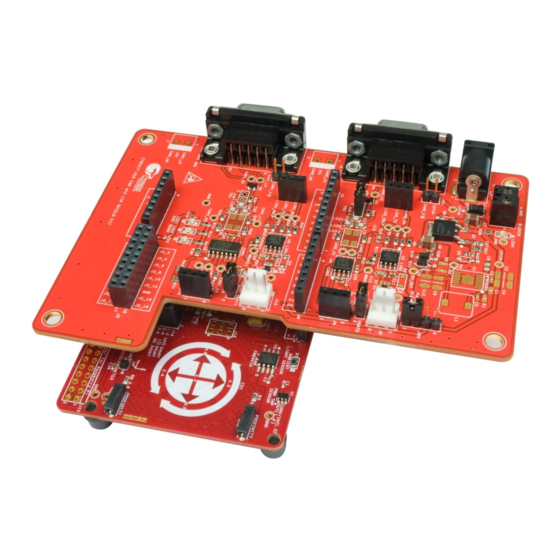
Summary of Contents for Cypress Semiconductor CY8CKIT-026
- Page 1 CY8CKIT-026 CAN and LIN Shield Kit Guide Doc. No. 002-03798 Rev. *C Cypress Semiconductor 198 Champion Court San Jose, CA 95134-1709 www.cypress.com...
- Page 2 Copyrights Copyrights © Cypress Semiconductor Corporation, 2015-2017. This document is the property of Cypress Semiconductor Corporation and its subsidiaries, including Spansion LLC ("Cypress"). This document, including any software or firmware included or ref- erenced in this document ("Software"), is owned by Cypress under the intellectual property laws and treaties of the United States and other countries worldwide.
-
Page 3: Table Of Contents
5. Example Projects Using the Kit Example Projects .................37 CAN_Simplex_Tx_CY8CKIT-044 ................38 CAN_Simplex_Rx_CY8CKIT-044................41 LIN_Slave_CY8CKIT-042 ..................45 LIN_Slave_CY8CKIT-044 ..................49 Multiple_LIN_Slave_CY8CKIT-042 ................49 Appendix 54 Schematics 54 Gerber Files 58 Bill of Materials 62 CY8CKIT-026 CAN and LIN Shield Kit Guide, Doc. No. 002-03798 Rev. *C... - Page 4 Safety Information Regulatory Compliance The CY8CKIT-026 CAN and LIN Shield Kit is intended for use as a development platform for hardware or software in a laboratory environment. The board is an open system design, which does not include a shielded enclosure. This may cause interference to other electrical or electronic devices in close proximity.
- Page 5 Use a conductive foam pad if available. Do not slide the board over any surface. CY8CKIT-026 CAN and LIN Shield Kit Guide, Doc. No. 002-03798 Rev. *C...
-
Page 6: Introduction
Introduction Thank you for your interest in the CY8CKIT-026 CAN and LIN Shield Kit. This kit is intended to ® demonstrate the CAN and LIN bus communications in Cypress’s PSoC products. The CY8CKIT-026 CAN and LIN Shield Kit is an Arduino compatible shield board that is used with several Cypress kits such as the CY8CKIT-042 PSoC 4 Pioneer Kit/CY8CKIT-044 PSoC 4 M-Series ®... -
Page 7: Getting Started
Therefore, it is recommended to have two CY8CKIT-044 Pioneer Kits or other compatible kits and two CY8CKIT-026 CAN and LIN Shield Kits. This enables you to set up CAN communication between two CAN nodes. An alternative recommendation is to have a CAN or LIN bus emulator or analyzer. - Page 8 1.2.3 Software Requirements The CY8CKIT-026 kit does not have any programmable/configurable device onboard, so it does not need any software for configuration. However, the PSoC device present on baseboards, such as CY8CKIT-042 or CY8CKIT-044, requires firmware, which you can develop with the PSoC Creator IDE (Version 3.3 SP1 or later).
-
Page 9: Additional Learning Resources
FM4-S6E2Gx Series and PSoC 4 M-Series. FM4 acts as Transmitter and PSoC 4 M acts as a receiver which changes the RGB LED color based on the commands received from the FM4. CY8CKIT-026 CAN and LIN Shield Kit Guide, Doc. No. 002-03798 Rev. *C... -
Page 10: Technical Support
Open. Displays an equation: Times New Roman 2 + 2 = 4 Text in gray boxes Describe s Cautions or unique functionality of the product. CY8CKIT-026 CAN and LIN Shield Kit Guide, Doc. No. 002-03798 Rev. *C... -
Page 11: Installation
CAN and LIN Shield Kit, you will require the PSoC Creator and PSoC Programmer software programs to be installed before the kit can be used. If you run the CY8CKIT-026 installer file (CY8CKIT026Setup.exe), this will install PSoC Creator and Programmer. Otherwise, you can... -
Page 12: Install Software
Installation Install Software 2.2.1 Installation from Internet Perform these steps to install the CY8CKIT-026 CAN and LIN Shield Kit software from the internet (this is done to ensure the latest software is installed): 1. Go to kit page. 2. Download and run the installer executable file (CY8CKIT026Setup.exe). - Page 13 These include PSoC Creator, PSoC Programmer, Windows Installer, .NET (v4.0), and Acrobat Reader. If these applications are not installed, the installer prompts you to download and/or install them. CY8CKIT-026 CAN and LIN Shield Kit Guide, Doc. No. 002-03798 Rev. *C...
-
Page 14: Uninstall Software
Installation Uninstall Software Perform these steps to uninstall the CY8CKIT-026 CAN and LIN Shield Kit software: 1. Go to Start > All Programs > Cypress > Cypress Update Manager and select the Uninstall button that corresponds to the kit software. Follow the on-screen prompts to uninstall the soft- ware. -
Page 15: Hardware
27. CAN2 screw terminal* 13. CAN2 termination resistor jumper 14. Arduino™ compatible main board 28. 12 V power jumper (from CAN2)* I/O header (J3 and J4) *Not populated CY8CKIT-026 CAN and LIN Shield Kit Guide, Doc. No. 002-03798 Rev. *C... - Page 16 Hardware Figure 3-2 Figure 3-3 show the top and bottom view of the CY8CKIT-026. Figure 3-2. CY8CKIT-026 (Top View) Figure 3-3. CY8CKIT-026 (Bottom View) CY8CKIT-026 CAN and LIN Shield Kit Guide, Doc. No. 002-03798 Rev. *C...
-
Page 17: Can Physical Layer Transceiver Circuits
CAN Physical Layer Transceiver Circuits The CY8CKIT-026 has two CAN transceivers: one is low speed (up to 125 Kbps baud rate) and fault tolerant, and the other is high speed (up to 2 Mbps baud rate). The PSoC 4M device supports two CAN modules, so these two transceivers enable you to use both of them to connect to CAN net- works. - Page 18 If J10 is not populated, the termination resistor is not active. By default, the termination resistor is active (J10 is populated). Figure 3-4. J10 Jumper CY8CKIT-026 CAN and LIN Shield Kit Guide, Doc. No. 002-03798 Rev. *C...
- Page 19 CAN Signal Connector for CAN2 Transceiver Table 3-3 shows the pinout of the 3-pin female CAN signal connector (J9) on the shield board. Table 3-3. CAN2 Signal Connector Pinout Signal CAN2_EN CAN2_TX CAN2_RX CY8CKIT-026 CAN and LIN Shield Kit Guide, Doc. No. 002-03798 Rev. *C...
-
Page 20: Lin Physical Layer Transceiver Circuits
CAN pin placement in the microcontroller is provided. LIN Physical Layer Transceiver Circuits The CY8CKIT-026 has two LIN transceivers. Since some PSoC 4 devices support two LIN slaves, these two transceivers enable you to use both of them simultaneously. - Page 21 GPIO (enable/sleep control) pin of the microcontroller respectively, using external connecting wires. These connections are not hard-wired on the board so that maximum flexibility for the LIN pin placement in the microcontroller is provided. CY8CKIT-026 CAN and LIN Shield Kit Guide, Doc. No. 002-03798 Rev. *C...
-
Page 22: Status Leds
The three LEDs (Red, Yellow, and Green) (see Figure 3-8) are connected to the D13, D12 and D11 pins of the Arduino connector (J3) respectively. Figure 3-8. Schematic for Status LEDs CY8CKIT-026 CAN and LIN Shield Kit Guide, Doc. No. 002-03798 Rev. *C... -
Page 23: Port Options With Cy8Ckit-042/044 Pioneer Kit
P1.5 P4.4 J2_8 P2.4 P2.4 P1.4 P4.5 J2_10 P2.5 P2.5 P1.3 P4.6 J2_12 P0.0 P0.0 J2_13 P0.1 P0.1 J2_15 P1.2 P3.4 J2_16 P1.0 P0.7 J2_17 P1.1 P3.5 J2_18 CY8CKIT-026 CAN and LIN Shield Kit Guide, Doc. No. 002-03798 Rev. *C... -
Page 24: Power Supply Configurations
1 and 2 of the 4-pin (1x4) connector (J20). This supplies 5 V to the shield board. Note that this will only allow CAN2 to be used since CAN1, LIN1 and LIN2 require a 12 V supply. CY8CKIT-026 CAN and LIN Shield Kit Guide, Doc. No. 002-03798 Rev. *C... - Page 25 Warning: Ensure extra care when providing the 12 V supply input to any of the J5, J8, J11, J12, J14 or J17 connectors. The supply should only be given to any one connector at a time. CY8CKIT-026 CAN and LIN Shield Kit Guide, Doc. No. 002-03798 Rev. *C...
- Page 26 Warning: The regulator can support up to 1 A current, connecting this to any circuit which draws more than 1 A current will damage the regulator. Do not provide any power through the test points. CY8CKIT-026 CAN and LIN Shield Kit Guide, Doc. No. 002-03798 Rev. *C...
- Page 27 An optional 12 V-5 V circuit is provided on the kit using a Cypress PMIC which is not populated. Figure 3-12 shows the Cypress PMIC schematic. Figure 3-12. Cypress PMIC Schematic CY8CKIT-026 CAN and LIN Shield Kit Guide, Doc. No. 002-03798 Rev. *C...
- Page 28 In both the above cases (options a and b), the baseboard power selection jumper (J9 on CY8CKIT-042 and CY8CKIT-044) should be at 3.3 V (only when USB is not connected to the baseboard). CY8CKIT-026 CAN and LIN Shield Kit Guide, Doc. No. 002-03798 Rev. *C...
- Page 29 These jumpers should only be shorted (pin 2 and 3, or pin 3 and 4 of J20 connector) when there is no input supply given on the VIN pin of the baseboard. CY8CKIT-026 CAN and LIN Shield Kit Guide, Doc. No. 002-03798 Rev. *C...
-
Page 30: Kit Operation
This chapter explains how to set-up the hardware connections in order to establish CAN and LIN communication using CY8CKIT-026. Default Jumper Settings on CY8CKIT-026 Table 4-1 shows the default jumper settings of the CY8CKIT-026 CAN and LIN Shield Kit. Table 4-1. Default Settings of the CY8CKIT-026 CAN and LIN Shield Kit Jumper Default Condition... - Page 31 5. Power up both the Shield Kits using any one of the supply options as explained in 3.6.4 Power Selection Jumper (J20). In Figure 4-1, both the Shield Kits are powered up with different 12 V supplies. CY8CKIT-026 CAN and LIN Shield Kit Guide, Doc. No. 002-03798 Rev. *C...
-
Page 32: Using Can Bus Analyzer Tool
CY8CKIT-026 Shield Kits are available. However, it is also possible to replace one CY8CKIT-044 Pioneer Kit and one CY8CKIT-026 Shield Kit with a CAN bus analyzer or emulator tool. It is even possible to use any other CAN node to communicate with this kit. - Page 33 You can modify the code examples, firmware, or settings of the other CAN node. See the Example Projects chapter on page 37 for more details on the CAN controller hardware configurations of this kit’s code examples. CY8CKIT-026 CAN and LIN Shield Kit Guide, Doc. No. 002-03798 Rev. *C...
-
Page 34: Lin Communication Hardware Setup
4. Connect a 12 V power supply input to the Shield Kit using any of the supply option described in 12 V Supply Input on page 25, and power the baseboard by populating the power selection jumper explained in Power Selection Jumper (J20) on page CY8CKIT-026 CAN and LIN Shield Kit Guide, Doc. No. 002-03798 Rev. *C... -
Page 35: Using Lin Bus Analyzer Tool
LIN example projects. Figure 4-5 Figure 4-6 show connecting a LIN Bus analyzer to the Shield Kit. Figure 4-5. LIN Analyzer Connection to CY8CKIT-026’s LIN1 Transceiver CY8CKIT-026 CAN and LIN Shield Kit Guide, Doc. No. 002-03798 Rev. *C... - Page 36 Kit Operation Figure 4-6. LIN Analyzer Connection to CY8CKIT-026’s LIN2 Transceiver CY8CKIT-026 CAN and LIN Shield Kit Guide, Doc. No. 002-03798 Rev. *C...
-
Page 37: Example Projects
1. Launch PSoC Creator from Start > All Programs > Cypress > PSoC Creator <version> > PSoC Creator <version>. 2. On the Start page, expand CY8CKIT-026 CAN and LIN Shield Kit under Examples and Kits > Kits. A list of example projects appears, as shown in Figure 5-1. -
Page 38: Can_Simplex_Tx_Cy8Ckit-044
(CY8CKIT-044) by shorting pin 1 and 2 of the power selection jumper (J20). 6. When you are powering the CY8CKIT-026 with the baseboard with 5 V, ensure that the jumper J9 on the baseboard (CY8CKIT-044) is in the 5 V position. When you are using 12 V external supply and powering the baseboard from the Shield Kit (without a USB connection), ensure that the jumper J9 on the baseboard (CY8CKIT-044) is in the 3.3 V position. - Page 39 The Sys Tec CAN analyzer is used as an example for this project. Data can be observed, as shown in Figure 5-2. Figure 5-2. CAN Data received on CAN Analyzer Software as Receiver CY8CKIT-026 CAN and LIN Shield Kit Guide, Doc. No. 002-03798 Rev. *C...
- Page 40 Example Projects 4. Perform these steps, if you are using another set of CY8CKIT-044 and CY8CKIT-026 for receiving the data: a. Program the second baseboard with the CAN_Simplex_Rx_CY8CKIT-044.hex file and set the hardware connections provided in Hardware Connections on page b.
-
Page 41: Can_Simplex_Rx_Cy8Ckit-044
(CY8CKIT-044) by shorting pin 1 and 2 of the power selection jumper (J20). 6. When you are powering the CY8CKIT-026 from the baseboard with 5 V, ensure that the jumper J9 on the baseboard (CY8CKIT-044) is set to the 5 V position. When you are using 12 V external supply and powering the baseboard from the Shield Kit (without a USB connection), ensure that the jumper J9 on the baseboard (CY8CKIT-044) is set to the 3.3 V selection. - Page 42 Figure 4-2 Figure 4-3 for receiving the transmitted data. 8. You can also use another CY8CKIT-044 and CY8CKIT-026 setup instead of a CAN analyzer, as shown in Figure 4-1, which should be programmed with the CAN_Simplex_Tx_CY8CKIT-044 project (described above) to transmit data over CAN.
- Page 43 If an error is displayed on the CAN analyzer software after transmitting the frame, reset the Kit-044 once and try transmitting the frame. 4. Perform these steps if you are using another set of CY8CKIT-044 and CY8CKIT-026 for receiving the data: a.
- Page 44 Note: For more details on the project that is used to configure the CAN component, CapSense component, IMO trimming, pin configurations, and so on refer to Code Example CE97311. CY8CKIT-026 CAN and LIN Shield Kit Guide, Doc. No. 002-03798 Rev. *C...
-
Page 45: Lin_Slave_Cy8Ckit-042
1. Plug-in the CY8CKIT-026 kit to the CY8CKIT-042 using the Arduino connectors. 2. Since there are two LIN transceivers on the CY8CKIT-026, choose either of the transceivers to use (U5 - LIN1 transceiver or U3 - LIN2 transceiver). Connect the Arduino header pins (which are... - Page 46 5. If you are using any other analyzer, make sure that the checksum setting is selected as enhanced checksum since LIN v2.1/2.2 specification supports only enhanced checksum (this option is not required in Silicon Engines LIN-USB converter software). CY8CKIT-026 CAN and LIN Shield Kit Guide, Doc. No. 002-03798 Rev. *C...
- Page 47 Table 5-8. Slave Response as per the Commands from Master Command Slave Response 0x11 Turns ON Red LED 0x22 Turns ON Green LED 0x33 Turns ON Blue LED 0x00 Turns OFF RGB LED CY8CKIT-026 CAN and LIN Shield Kit Guide, Doc. No. 002-03798 Rev. *C...
- Page 48 Note: For more details on how to configure the LIN component, pin configurations, and so on refer to Code Example CE96999. Note: If there is an error message such as “BUS STUCK HIGH” or “TX FRAME ERROR”, reset the baseboard (CY8CKIT-042/44) and LIN analyzer. CY8CKIT-026 CAN and LIN Shield Kit Guide, Doc. No. 002-03798 Rev. *C...
-
Page 49: Lin_Slave_Cy8Ckit-044
3. Connect the LIN1 analyzer to the J14 connector and LIN2 analyzer to J5 connector on the CY8CKIT-026 Kit. Since there are two LIN slaves in this project, you need to have two LIN analyzers - each should connect to one LIN slave. - Page 50 If a frame with ID = 0x11 is received from the LIN1 analyzer, then the slave will send the stored CapSense linear slider centroid position back to the analyzer. CY8CKIT-026 CAN and LIN Shield Kit Guide, Doc. No. 002-03798 Rev. *C...
- Page 51 Open the LIN2 analyzer software and go to Configure LIN/USB, set the LIN Bus Baud Rate to 19200 bps, and then deselect the LIN 2.0-2.1 Protocol checkbox as shown in Figure 5-11. Figure 5-11. LIN2 analyzer Configuration CY8CKIT-026 CAN and LIN Shield Kit Guide, Doc. No. 002-03798 Rev. *C...
- Page 52 0xCC 0xDD RGB LED OFF e. The result of transmitted and received data at the LIN2 analyzer is shown in Figure 5-12. Figure 5-12. Results at LIN2 analyzer CY8CKIT-026 CAN and LIN Shield Kit Guide, Doc. No. 002-03798 Rev. *C...
- Page 53 Note: For more details on how to configure the LIN component, pin configurations, and so on refer to Code Example CE96999. Note: If there is an error message such as “BUS STUCK HIGH” or “TX FRAME ERROR”, reset the baseboard (CY8CKIT-042) and LIN analyzer. CY8CKIT-026 CAN and LIN Shield Kit Guide, Doc. No. 002-03798 Rev. *C...
-
Page 54: Appendix
Appendix Schematics Figure A-1. Power Supply Circuit Schematic CY8CKIT-026 CAN and LIN Shield Kit Guide, Doc. No. 002-03798 Rev. *C... - Page 55 Figure A-2. CAN1 and CAN2 Transceiver Circuit Schematic CY8CKIT-026 CAN and LIN Shield Kit Guide, Doc. No. 002-03798 Rev. *C...
- Page 56 Figure A-3. LIN1 and LIN2 Transceiver Circuit Schematic CY8CKIT-026 CAN and LIN Shield Kit Guide, Doc. No. 002-03798 Rev. *C...
- Page 57 Figure A-4. Arduino Header and Status LEDs Schematic CY8CKIT-026 CAN and LIN Shield Kit Guide, Doc. No. 002-03798 Rev. *C...
-
Page 58: Gerber Files
Gerber Files Figure A-5. CY8CKIT-026 Primary Side CY8CKIT-026 CAN and LIN Shield Kit Guide, Doc. No. 002-03798 Rev. *C... - Page 59 Figure A-6. CY8CKIT-026 Secondary Side CY8CKIT-026 CAN and LIN Shield Kit Guide, Doc. No. 002-03798 Rev. *C...
- Page 60 Figure A-7. CY8CKIT-026 Primary Silk Screen CY8CKIT-026 CAN and LIN Shield Kit Guide, Doc. No. 002-03798 Rev. *C...
- Page 61 Figure A-8. CY8CKIT-026 Secondary Silk Screen CY8CKIT-026 CAN and LIN Shield Kit Guide, Doc. No. 002-03798 Rev. *C...
-
Page 62: Bill Of Materials
J5,J14 Molex Inc. 22232031 .100 VERT TIN [KEYED] Connector Header 3 Position 0.100" Sullins Connector PPPC031LFB 3x1 Recp (2.54 mm) Gold J6,J9,J15,J19 Solutions N-RC Through Hole [Female Socket] CONN HEADR BRKWAY J7,J10,J13,J1 TE Connectivity 2x1 Jumper 5-146280-2 6,J21 .100 2POS STR AMP Connectors CY8CKIT-026 CAN and LIN Shield Kit Guide, Doc. No. 002-03798 Rev. *C... - Page 63 120 ohm R30,R36, Electronic 1% 1/8 W 0805 6ENF1200V Components IC REG LDO 5 V 1 A NCV1117DT50 NCV1117DT50 ON Semiconductor DPAK IC TRANSCEIVER LIN TJA1020T/ TJA1020 U3,U5 8SOIC Semiconductors CM,118 IC CAN TRANSEIVER HS TJA1051T/ TJA1051T/3 8SOIC Semiconductors 3,118 CY8CKIT-026 CAN and LIN Shield Kit Guide, Doc. No. 002-03798 Rev. *C...
- Page 64 EPCOS / TDK [Common Mode Filters / Chokes] Panasonic RES SMD 0.0 OHM ERJ- ZERO Electronic JUMPER 1/10 W 3GEY0R00V Components Panasonic RES SMD 100 KOHM ERJ- 100K Electronic 1% 1/10 W 0603 3EKF1003V Components CY8CKIT-026 CAN and LIN Shield Kit Guide, Doc. No. 002-03798 Rev. *C...
- Page 65 65 PLATED BLACK Electronics TP6,TP7, TP8, TP9, TP10, TP11, TP12, TP13, ,TP14,TP15, TEST POINT 43 Keystone TP16,TP17,TP18 WHITE HOLE 65 PLATED 5002 Electronics WHITE ,TP19,TP20,TP2 1,TP22,TP23,TP 24,TP25, TP26, TP27,TP28,TP31 S6BP202A is a single S6BP202A output Buck‐Boost DC/ Cypress S6BP202A DC, TSSOP‐16 PIN CY8CKIT-026 CAN and LIN Shield Kit Guide, Doc. No. 002-03798 Rev. *C...
- Page 66 “Kit Compatibility” on page 5169205 03/10/2016 MVRE Updated description. Updated Hardware chapter on page Updated “System Block Diagram” on page Updated description. 5713267 04/26/2017 SHEA Updated logo and copyright CY8CKIT-026 CAN and LIN Shield Kit Guide, Doc. No. 002-03798 Rev. *C...
- Page 67 Mouser Electronics Authorized Distributor Click to View Pricing, Inventory, Delivery & Lifecycle Information: Cypress Semiconductor CY8CKIT-026...
Need help?
Do you have a question about the CY8CKIT-026 and is the answer not in the manual?
Questions and answers