
Related Manuals for Mitsubishi Electric melfa RV-5AS


Summary of Contents for Mitsubishi Electric melfa RV-5AS
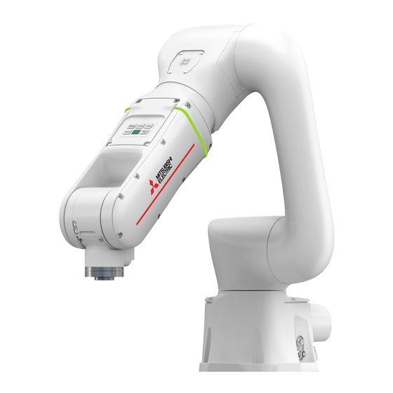
- Page 1 Mitsubishi Electric Industrial Robot RV-5AS Instruction Manual Robot Arm Setup and Maintenance BFP-A3729-A...
- Page 3 Safety Precautions Always read the following precautions and the separate "Collaborative Robot Safety Manual" before starting use of the robot to learn the required measures to be taken. ■Basic precautions and important points when using collaborative robots Collaborative robots have a variety of safety functions, so unlike conventional industrial robots, they can work in the same space as humans without being separated by a machine guard.
- Page 4 Revision history Date of Print Instruction Manual No. Revision Details 2020-04-10 BFP-A3729 • First print 2020-07-30 BFP-A3729-A • Revised the guidelines for unpacking the robot.
- Page 5 Please contact your nearest dealer if you find any doubtful, wrong or skipped point. • This is the original document. • Company names and production names in this document are the trademarks or registered trademarks of their respective owners. Copyright(C) 2020 MITSUBISHI ELECTRIC CORPORATION...
-
Page 6: Table Of Contents
CONTENTS Page 1 Before starting use .......................... 1-1 1.1 Using the instruction manuals ....................1-1 1.1.1 The details of each instruction manuals ................1-1 1.1.2 Symbols used in this manual ....................1-2 2 Unpacking to Installation ......................... 2-3 2.1 Confirming the product ......................2-3 2.2 Installation .......................... -
Page 7: Before Starting Use
1 Before starting use 1 Before starting use This chapter explains how to use this manual. It also contains information on safety and the basic symbols used in it. Moreover, handling and operation of a teaching pendant (T/B) are described based on R32TB in instruction manuals. -
Page 8: Symbols Used In This Manual
1 Before starting use 1.1.2 Symbols used in this manual Symbols used in this manual are explained in Table 1-1. Learn the meaning of these symbols before reading this instruction manual. Table 1-1:Symbols in instruction manual Terminology Symbol Meaning Precaution indicating cases where there is a risk of operator fatality or DANGER serious injury if handling is mistaken. -
Page 9: Unpacking To Installation
2 Unpacking to Installation 2 Unpacking to Installation 2.1 Confirming the product The standard configuration of the robot arm, part of the purchased product, is shown in Table 2-1. Confirm the parts. Users who have purchased optional products should refer to the separate "Standard Specifications Man- ual". - Page 10 2 Unpacking to Installation 2) Pull the box up and remove it. 3) Remove the left and right inserts. Inserts 4) Remove the top inserts. Inserts 2-4 Installation...
- Page 11 2 Unpacking to Installation 5) Open the plastic bag covering the robot. Plastic bag 6) Remove the robot from the box. When lifting the robot, one person should hold the end of the forearm and elbow, while another person holds the area under the elbow. Elbow End of the forearm Mass:...
- Page 12 2 Unpacking to Installation 7) Remove the support bracket for the mechanical interface once the robot has been installed. Support bracket CAUTION The support bracket and packaging are required when relocating the robot. Keep them in a safe place. 2-6 Installation...
-
Page 13: Transportation Procedure (With Two People)
2 Unpacking to Installation 2.2.2 Transportation procedure (with two people) Elbow End of the forearm (Robot) Mass: 32kg Fig.2-1: Transportation of robot arm (Transportation by people) 1) The robot must be transported by two workers. Use a cart or other device for transporting the robot near the installation place. -
Page 14: Installation Procedures
2 Unpacking to Installation 2.2.3 Installation procedures The installation procedure of the robot arm is shown below. Installation bolt: 4-M8×35 Spring washer Plain washer <Bottom view> (135) 67.5 67.5 (Installation) (80) Ra6.3 Bottom view: Installation dimensions Fig.2-2: Installation dimensions 1) The base of the robot has already been machined flat. There are four installation holes (φ9) on the base of the robot. -
Page 15: Ceiling Mounting Procedure
2 Unpacking to Installation Table 2-3:Strength of the installation side (reference) Unit Value Item Tilt moment N•m Torsional moment N•m Horizontal direction translation force Vertical direction translation force: F 1,010 CAUTION During installation, ensure that there is enough space at the rear of the robot to connect the machine cable. - Page 16 2 Unpacking to Installation 3) Face the robot elbow down. Use two people to support the robot, then face the base upward towards the installation area. 4) While the two people support the robot, have a third person lift the pallet up with the forklift so that the base of the robot comes into contact with the installation area.
-
Page 17: Grounding Procedures
2 Unpacking to Installation 2.2.5 Grounding procedures (1) Grounding methods 1) As indicated in Fig. 2-3, there are three ways of grounding (earthing) the RV-5AS. The most preferable of the three is "a". Do not use "c". For information on grounding (earthing) the robot controller, refer to the separate Instruction Manual "Controller Setup and Maintenance". -
Page 18: Connecting With The Controller
2 Unpacking to Installation 2.2.6 Connecting with the controller Fig.2-5: Connecting the machine cables Carry out the following procedure after installing the controller referring to the separate "Controller Setup and Maintenance" manual. Latch Machine cable controller side connector CN1 connector Fig.2-6: Connecting with the controller 1) Make sure that the power of the controller is turned OFF. - Page 19 2 Unpacking to Installation CAUTION Take special care to the leading of the connection cable. If the cable is pulled with force or bent excessively, wires could break or the connector could be damaged. CAUTION Connect the machine cable at the place without the effect of the dust or oil mist. Installation 2-13...
-
Page 20: Confirming The Operation
2 Unpacking to Installation 2.3 Confirming the operation After the robot is connected to the controller, the origin data is automatically written. Then, manually move the robot using the T/B to confirm that the operation is correct. Moving the robot manually is called "jog operation". This operation includes the JOINT jog that moves each axis, the XYZ jog that moves along the base coordinate system, the TOOL jog that moves along the tool coordinate system, the Work jog that moves along the work coordinate system, and the CYLNDER jog that moves along the circular arc. -
Page 21: Installing The Teaching Pendant (T/B)
2 Unpacking to Installation 2.3.1 Installing the teaching pendant (T/B) Installing the T/B, with turning off the controller power. CAUTION Please do not pull the cable of T/B strongly or do not bend it too much. It becomes the breaking of a wire of the cable and the cause of breakage of the connector. -
Page 22: Preparing The T/B
2 Unpacking to Installation 2.3.3 Preparing the T/B Next, prepare to use the T/B 1) Set the mode of the controller to "MANUAL". 2) Set the T/B [ENABLE] switch to "ENABLE". The menu selection screen will appear. The following operations are carried out with the T/B. Disable 上:DISABLE Down: Enable... - Page 23 2 Unpacking to Installation J4 axis J3 axis J5 axis J6 axis J2 axis J1 axis * Each axis moves independently. Fig. 2-8: JOINT jog operation Tool length Control point * The axis moves straight along the XYZ coordinate system. The flange surface posture is maintained. Also, while maintaining the flange surface position, the flange surface posture changes.
- Page 24 2 Unpacking to Installation Tool length Control point * While maintaining the flange surface posture, the axis moves straight along the tool coordinate sys- tem. Also, while maintaining the flange surface position, the flange surface posture changes. Fig. 2-10: TOOL jog operation J4 axis Tool length J5 axis...
- Page 25 2 Unpacking to Installation Tool length Vertical Radius Control point * The current position is set as the arc centering on the Z axis, and the axis moves along that arc, expands and contracts in the radius direction, and moves vertically. At this time, the flange surface posture is maintained.
-
Page 26: Joint Jog Operation
2 Unpacking to Installation (1) JOINT jog operation Select joint jog mode [JOG] Press the key and display the jog screen. ("JOG" is displayed on the screen bot- <CURRENT> JOINT 100% M1 T0 tom) +0.00 +0.00 Check that the "joint" in jog mode is displayed +0.00 +0.00 on the screen. - Page 27 2 Unpacking to Installation J3 axis jog operation J3 axis • When the [+Z (J3)] keys is pressed, the J3 axis will rotate in the plus direction. When the [-Z (J3)] keys is pressed, rotate in the minus direction. J4, J5 and J6 axis jog operation J4 axis J5 axis J6 axis...
-
Page 28: Xyz Jog Operation
2 Unpacking to Installation (2) XYZ jog operation Select XYZ jog mode [JOG] Press the key and display the jog <CURRENT> XYZ 100% screen. ("JOG" is displayed on the screen bot- X: +977.45 A: -180.00 tom) +0.00 +89.85 Check that the "XYZ" in jog mode is displayed Z: +928.24 C: +180.00 on the screen. - Page 29 2 Unpacking to Installation If the buzzer of T/B sounds and the robot does not move If it is going to move the robot across the operation range, the buzzer of T/B sounds and the robot does not move. In this case, please move to the counter direction. Changing the flange surface posture SPACE Tool length...
-
Page 30: Tool Jog Operation
2 Unpacking to Installation (3) TOOL jog operation Select TOOL jog mode [JOG] Press the key and display the jog screen. ("JOG" is displayed on the screen bot- <CURRENT> TOOL 100% tom) X: +977.45 A: -180.00 Check that the "TOOL" in jog mode is dis- +0.00 +89.85 Z: +928.24... - Page 31 2 Unpacking to Installation If the buzzer of T/B sounds and the robot does not move If it is going to move the robot across the operation range, the buzzer of T/B sounds and the robot does not move. In this case, please move to the counter direction. Changing the flange surface posture Tool length SPACE...
-
Page 32: 3-Axis Xyz Jog Operation
2 Unpacking to Installation (4) 3-axis XYZ jog operation Select 3-axis XYZ jog mode [JOG] Press the key and display the jog screen. ("JOG" is displayed on the screen bot- <CURRENT> 3-XYZ 100% tom) X: +977.45 A: -180.00 +0.00 +89.85 Check that the "3-XYZ"... - Page 33 2 Unpacking to Installation Changing the flange surface posture J4 axis J5 axis J6 axis SPACE * The wrist pose can be changed maintaining the flange's position. • When the [+A (J4)] key is pressed, the J4 axis will rotate in the plus direction. At this time, to maintain the flange's position, other axes move simultaneously except J5 and J6.
-
Page 34: Cylnder Jog Operation
2 Unpacking to Installation jog operation CYLNDER Select cylindrical jog mode [JOG] Press the key and display the jog screen. ("JOG" is displayed on the screen bot- <CURRENT> CYLNDER 100% tom) X: +977.45 A: -180.00 +0.00 +89.85 Check that the "CYLNDER" in jog mode is dis- Z: +928.24 C: +180.00 played on the screen. - Page 35 2 Unpacking to Installation Changing the flange surface posture SPACE Tool length Control point * The flange position does not change. This is the same as the A, B and C axis XYZ jog operation. • When the [+A (J4)] key is pressed, the axis will rotate around the X axis in the plus direction. When the [-A (J4)] keys is pressed, rotate in the minus direction.
-
Page 36: Work Jog Operation
2 Unpacking to Installation (6) Work jog operation Setting of the work coordinates system is necessary. By this jog operation, robot can be move along with the direction of work (or working table etc.), so teaching operations get easier. When jog operation, select by which work coordinates the robot moves The setting method of the work coordinates system using T/B (R32TB) is shown in the following. - Page 37 2 Unpacking to Installation 3) Selection of the work coordinates number Press the [FUNCTION] keys, and display "W: JUMP" function. Press the function key corresponding to "W: JUMP" <WORK JUMP> <WORK COORD> WORK NUMBER (1) TEACHING POINT (WO) CHOOSE ONE OF THE WORK NUMBER X: 0.00 1-8.
- Page 38 2 Unpacking to Installation 5) Setting of work coordinates (definition) If the function key corresponding to "DEFINE" ([F1]) is pressed, the work coordinates system will be cal- culated using the three points, and the result will be displayed. <WORK COORD> WORK NUMBER (2) <WORK COORD>...
- Page 39 2 Unpacking to Installation Select WORK jog mode [JOG] Press the key and display the jog screen. ("JOG" is displayed on the screen bot- <CURRENT> WORK 100% M1 T0 W1 tom) +0.00 +0.00 Check that the "WORK" in jog mode is dis- +0.00 +0.00 played on the screen.
- Page 40 2 Unpacking to Installation The jog movement based on work coordinates system Tool length Control point Work coordinates system * The direction of the flange will not change. Move the control point with a straight line in accordance with the work coordinates system •...
- Page 41 2 Unpacking to Installation Changing the flange surface posture <1> Work jog mode +Zw′ Tool length +Xw′ Control point +Yw′ Work coordinates system * The position of the control point does not change. Change the direction of the flange in accordance with the work coordinates system. •...
- Page 42 2 Unpacking to Installation <2> Ex-T jog mode Control point Control point Work coordinates system Work coordinates system (Ex-T coordinates system) (Ex-T coordinates system) Control point Work coordinates system (Ex-T coordinates system) * The control point rotates around each axes of work coordinates system (Ex-T coordinates system). When the [+A (J4)] or the [-A (J4)] key is pressed, the control point rotates around the Xw axis.
-
Page 43: Setting The Hand Parameters
2 Unpacking to Installation Tool length The default tool length is 0mm, and the control point is the center of the end axis. After installing the hand, set the correct tool length in the parameters. Refer to the separate manual "Detailed Explanation of Functions and Operations"... -
Page 44: Installing The Option Devices
3 Installing the option devices 3 Installing the option devices 3.1 Installing the solenoid valve set This section explains how to install and connect the solenoid valve set. The installation steps are shown below. Turn off the power of the robot controller before attempting these steps. 1) Remove the M4 truss screws attaching the base cover to the back of the robot (four places), then gen- tly remove the base cover. - Page 45 3 Installing the option devices 3) First, connect the φ6 RETURN air hose (black) to the R port (quick coupling) of the solenoid valve set. Then, connect the φ6 AIR IN air hose (white) to the P port (quick coupling) of the solenoid valve set. φ6 RETURN air hose φ6 AIR IN air hose (black)
- Page 46 3 Installing the option devices Table 3-1:Hand to solenoid connection Hand Hand condition Solenoid valve port No. Φ4 air hose No. Solenoid valve set in use Open A port (1) Hand 1 One set Close B port (2) Open A port (3) Hand 2 Two sets Close...
- Page 47 3 Installing the option devices CAUTION Ensure that the wires do not protrude beyond the gasket. Wires Gasket 7) Re-install the cover. Then, fix the cover in place using the screws for the cover. (Recommended tight- ening torque: 1.64 N•m) CAUTION Be careful not to damage the gasket when re-installing the cover.
-
Page 48: Maintenance And Inspection
4 Maintenance and Inspection 4 Maintenance and Inspection The maintenance and inspection procedures to be carried out to use the robot for a long time without trouble are described in this chapter. 4.1 Type of inspection and maintenance works Maintenance and inspection are divided into the inspections carried out daily, and the periodic inspections carry out at set intervals. -
Page 49: Inspection Items
4 Maintenance and Inspection 4.2 Inspection items The inspection items for the robot arm are shown below. Also refer to section "Maintenance and inspection" in the "Controller Setup and Maintenance" manual, and inspect the controller. 4.2.1 Daily inspection items Table 4-2 shows the procedure and inspection items. -
Page 50: Periodic Inspection
4 Maintenance and Inspection 4.2.2 Periodic inspection The inspection items and timings for the robot arm are shown below. (1) Inspection item Carry out periodic inspection given in Table 4-3. Table 4-3: Periodic inspection items (details) Inspection item (details) Remedies Monthly inspection Are any of the bolts or screws on the robot arm loose? Securely tighten the bolts. -
Page 51: Schedule
4 Maintenance and Inspection (2) Schedule The following shows the schedule for the periodic inspection works. Perform the periodic inspection works as appropriate according to the following table. Type of periodic inspection Inspection schedule Operating time Note2) works Note1) 15 hours per day 8 hours per day Monthly inspection 300hr... -
Page 52: About Overhaul
4 Maintenance and Inspection 4.3 About Overhaul Robots which have been in operation for an extended period of time can suffer from wear and other forms of deterioration. In regard to such robots, we define overhaul as an operation to replace parts running out of specified service life or other parts which have been damaged, so that the robots may be put back in shape for continued use. -
Page 53: Maintenance Parts
Table 4-4. Only purchase parts directly from specified vendors or the Mitsubishi Electric Service Department. [Note] Some Mitsubishi-designated parts differ from the maker's standard parts. Thus, confirm the part name, robot arm and controller serial No. and purchase the parts from the dealer. -
Page 54: How To Release The Brake In An Emergency
5 Maintenance and Inspection 4.5 How to release the brake in an emergency The following describes how to release the brake using the emergency power supply in an emergency. Using an emergency power supply system separated from the primary power supply of the robot prevents the robot from moving accidentally during the brake release operation, which contributes to enhancing customer safety. - Page 56 HEAD OFFICE: TOKYO BUILDING, 2-7-3, MARUNOUCHI, CHIYODA-KU, TOKYO 100-8310, JAPAN NAGOYA WORKS: 5-1-14, YADA-MINAMI, HIGASHI-KU NAGOYA 461-8670, JAPAN Authorised representative: Mitsubishi Electric Europe B.V. FA - European Business Group Mitsubishi-Electric-Platz 1, D-40882 Ratingen, Germany Tel: +49(0)2102-4860 Jul. 2020 MEE Printed in Japan on recycled paper.
Need help?
Do you have a question about the melfa RV-5AS and is the answer not in the manual?
Questions and answers