Table of Contents
Advertisement
Advertisement
Table of Contents

Subscribe to Our Youtube Channel
Related Manuals for Leica Zeno 10


Summary of Contents for Leica Zeno 10
- Page 1 Leica Zeno 10/Zeno 15 User Manual Version 4.1 English...
- Page 2 The type and serial number of your product are indicated on the type plate. tion Enter the type and serial number in your manual and always refer to this information when you need to contact your agency or Leica Geosystems authorised service work- shop. Type: _______________ Serial No.:...
- Page 3 Important paragraphs which must be adhered to in practice as they enable the product to be used in a technically correct and efficient manner. Zeno 10/Zeno 15, Introduction...
- Page 4 SD Logo is a trademark of SD-3C, LLC. All other trademarks are the property of their respective owners. Validity of this This manual applies to the Zeno 10 and Zeno 15 GNSS/GIS handhelds. Differences manual between the various models are marked and described.
- Page 5 Overall comprehensive help to the product and applica- tion functions. Included are detailed descriptions of special software/hardware settings and software/hard- ware functions. * only available as Online Help Refer to the following resources for all Zeno 10/Zeno 15 documentation/soft- ware: • the Leica Zeno GIS DVD •...
- Page 6 View the service history of your products in Leica Geosystems Service Centers and detailed information on the services performed on your products. For your products that are currently in Leica Geosystems Service Centers view the current service status and the expected end date of service.
-
Page 7: Table Of Contents
Description of the System Overview Terminology System Concept 1.3.1 Software Concept 1.3.2 Power Concept 1.3.3 Data Storage Concept CS Components 1.4.1 CS10 1.4.2 CS15 Docking Station Components User Interface Keyboard Operating Principles Operation Equipment Setup Zeno 10/Zeno 15, Table of Contents... -
Page 8: Zeno 10/Zeno 15, Table Of Contents
Zeno 10/Zeno 15, Table of Contents 3.1.1 Fixing the Display Foil to the CS 3.1.2 Fixing a Hand Strap to the CS 3.1.3 Fixing the Slot Cover to the CS 3.1.4 Inserting and Removing a SIM Card 3.1.5 Setting up as Handheld GNSS 3.1.6... - Page 9 Technical Data CS10/CS15 Technical Data GS05/GS06 Technical Data 6.2.1 Tracking Characteristics 6.2.2 Accuracy 6.2.3 Technical Data GG03 Technical Data 6.3.1 Tracking Characteristics 6.3.2 Accuracy 6.3.3 Technical Data Antennas Technical Data Conformity to National Regulations Zeno 10/Zeno 15, Table of Contents...
- Page 10 Zeno 10/Zeno 15, Table of Contents 6.5.1 CS10 6.5.2 CS15 6.5.3 GG03 Software Licence Agreement Appendix A Pin Assignments and Sockets CS10/CS15 GG03 Index...
-
Page 11: Description Of The System
Description of the System Overview System compo- nents GS06 GS05 GG03 CS10 CS15 003039_002 Zeno 10/Zeno 15, Description of the System... -
Page 12: Terminology
CS is a collective term describing the various models (CS10/CS15) of the multi- tion purpose field controller. Zeno general Zeno is a collective term describing the various models (Zeno 10/Zeno 15) of the description Leica Zeno GNSS/GIS handhelds: • Leica Zeno 10: GNSS/GIS handheld consisting of CS10 field controller and GS05 GNSS cap. - Page 13 CS15 GIS CS15 3.5G GIS Use the supplied stylus on the screens of the touch screen. *1 removable Zeno 10/Zeno 15, Description of the System...
-
Page 14: System Concept
Zeno 10/Zeno 15, Description of the System System Concept 1.3.1 Software Concept Software for all CS Software type Description models CS firmware This software includes: (CS_xx.fw) - The language-specific version of Windows CE. - The basic functionality of the CS. - Page 15 Connect the CS field controller to your PC. Refer to "3.1.7 Connecting to a Personal Computer". • Copy CS firmware file onto a folder on the Leica SD card, Leica CompactFlash card or USB stick. • Tap the Loader icon from the desktop, to run the Loader application.
- Page 16 Connect the CS field controller to your PC. Refer to "3.1.7 Connecting to a Personal Computer". • Copy GS firmware file onto a folder on the Leica SD card, Leica CompactFlash card or USB stick. • Click on Start > Programs > Zeno Tools > Firmware, to run the Firmware loader application.
- Page 17 Leica SD card or Leica CompactFlash card. • Connect the GG with the GEV234/GEV237 cable to the CS field controller and establish a connection between the GG and the CS field controller. Refer to the Leica Viva Technical Reference Manual (Connections.. - Connec- tions..). •...
-
Page 18: Power Concept
Zeno 10/Zeno 15, Description of the System 1.3.2 Power Concept General Use the Leica Geosystems batteries, chargers and accessories or accessories recom- mended by Leica Geosystems to ensure the correct functionality of the instrument. Power options Model Power supply all CS models... -
Page 19: Data Storage Concept
While other SD cards or CompactFlash cards can be used, Leica Geosystems recommends to only use Leica SD cards or Leica CompactFlash cards and is not responsible for data loss or any other error that can occur while using a non-Leica card. - Page 20 Data can be transferred in various ways. Refer to "3.1.7 Connecting to a Personal Computer". CompactFlash cards and SD cards can directly be used in an OMNI drive as supplied by Leica Geosystems. Other PC card drives can require an adaptor.
-
Page 21: Cs Components
Slot Cover b) Screen c) Keyboard d) Port cover e) Power socket USB A Host port g) Docking station contacts h) LEMO port (USB and serial) USB Mini port DSUB9 port CS_001 Zeno 10/Zeno 15, Description of the System... - Page 22 Zeno 10/Zeno 15, Description of the System Underside of CS10 a) Hand strap bottom clips b) Hand strap c) Battery compartment d) Digital camera e) Hand strap top clips Slots g) Slot cover h) Stylus GS05 contacts CompactFlash card slot...
-
Page 23: Cs15
Slot cover b) Screen c) Keyboard d) Port cover e) Power socket USB A Host port g) Docking station contacts h) LEMO port (USB and serial) USB Mini port DSUB9 port CS_002 Zeno 10/Zeno 15, Description of the System... - Page 24 Zeno 10/Zeno 15, Description of the System Underside of CS15 a) Hand strap bottom clips b) Hand strap c) Battery compartment d) Digital camera e) Hand strap top clips Slots g) Slot cover h) Stylus GS06 contacts CompactFlash card slot...
-
Page 25: Docking Station Components
Docking Station Components Docking station a) Power socket b) USB port c) Docking station bracket d) Docking station contacts e) GEV223 data cable CS_020 Zeno 10/Zeno 15, Description of the System... -
Page 26: User Interface
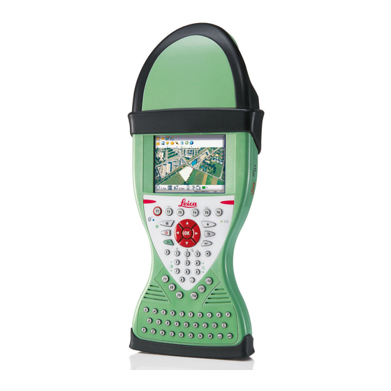
Zeno 10/Zeno 15, User Interface User Interface Keyboard Keyboard display CS10 a) Home b) ON/OFF c) Arrow keys, OK d) Fn e) ± key Brightness g) Keyboard illumination h) Favourites Enter PQRS WXYZ k) Backspace Volume m) Numeric keys CS_005... - Page 27 Brightness h) Keyboard illumination Function keys F7 - F12 CAPS Lock k) Function keys F1 - F6 Favourites m) ESC n) ENTER o) Backspace p) Volume q) Alpha keys ENTER s) SPACE CS 006 Zeno 10/Zeno 15, User Interface...
- Page 28 Zeno 10/Zeno 15, User Interface Keys Function Function keys Correspond to six softkeys that appear on the bottom F1-F6 of the screen when the screen is activated. Function keys User definable keys to execute chosen commands or F7-F12 access chosen screens.
- Page 29 Turns to Power Options menu when held for 2 s. Refer to "Power Options menu". • Turns off CS10/CS15 when held for 5 s. Favourites Goes to a website by simply clicking its name. Home Switches to the Windows CE Start Menu. Zeno 10/Zeno 15, User Interface...
- Page 30 Zeno 10/Zeno 15, User Interface Function Arrow keys Move the focus on the screen. Selects the highlighted line and leads to the next logical menu/ dialog. Starts the edit mode for editable fields. Opens a selectable list. Key combinations Function Hold Fn while pressing 4.
- Page 31 Function Hold Fn while pressing 0. If keyboard illumination is already off: Turns on keyboard illumination. If keyboard illumination is already on: Turns off keyboard illumination. Zeno 10/Zeno 15, User Interface...
-
Page 32: Operating Principles
Zeno 10/Zeno 15, User Interface Operating Principles Keyboard and The user interface is operated either by the keyboard or by the touch screen with touch screen supplied stylus. The workflow is the same for keyboard and touch screen entry, the only difference lies in the way information is selected and entered. -
Page 33: Operation
Touch the silver-coloured sticker with two fingers and pull it slowly upwards. The carrier foil is peeling away. Do not peel the carrier foil more than 2 cm - 3 cm away. Zeno 10/Zeno 15, Operation... - Page 34 Zeno 10/Zeno 15, Operation Step Description Fix the laid open adhesive underside of the display foil at the display border. Pay attention that the display foil is not fixed between display and display frame. Peel away the carrier foil bit by bit and smooth it out slowly onto the display.
-
Page 35: Fixing A Hand Strap To The Cs
Compress the clips of the main hook. Lower the main hook onto the pivot knob of the CS field controller. A click can be felt when the clip is secure. Adjust the length of the hand strap. Zeno 10/Zeno 15, Operation... -
Page 36: Fixing The Slot Cover To The Cs
Zeno 10/Zeno 15, Operation 3.1.3 Fixing the Slot Cover to the CS Fixing the slot cover to the CS step-by-step CS_016 Step Description Press the screwdriver end of the supplied stylus on the quarter-turn screws and loosen them. Remove the slot cover. -
Page 37: Inserting And Removing A Sim Card
Loosen the screws inside the slot cover on top of the CS10/CS15 using the screwdriver end of the stylus. Detach the slot cover from the CS10/CS15. Slide the card firmly into the slot until it clicks into position. Zeno 10/Zeno 15, Operation... - Page 38 Zeno 10/Zeno 15, Operation Description Do not force the card into the slot. The card should be held with the contacts facing the slot. Attach the slot cover and tighten the screws. To remove the card, detach the slot cover of the CS10/CS15.
-
Page 39: Setting Up As Handheld Gnss
CS10 step- by-step CS_011 Step Description Detach the slot cover from the CS10. Refer to "3.1.3 Fixing the Slot Cover to the CS". Check the position of the contacts in the inner surface of the GS05. Zeno 10/Zeno 15, Operation... - Page 40 Zeno 10/Zeno 15, Operation Step Description Attach the GS05 to the CS10. Press the screwdriver end of the supplied stylus on the quarter-turn screws and tighten them. To achieve the optimal satellite tracking performance, mount the AS05 (external GNSS antenna) on the GS05.
-
Page 41: Setting Up The Docking Station
Hold the docking station bracket as shown in the illustration in relation to the docking station rack. Slightly press the holder into the docking station rack. A click can be felt when the holder is secure. Zeno 10/Zeno 15, Operation... -
Page 42: Connecting To A Personal Computer
Insert the Leica Viva Series DVD. Run the SetupViva&GR_USB_XX.exe to install the drivers necessary for Leica Viva devices. Depending on the version (32bit or 64bit) of the oper- ating system on your PC, you have to select between the three setup files following: •... - Page 43 Step Description The Welcome to InstallShield Wizard for Leica Viva & GR USB drivers window appears. Ensure that all Leica Viva devices are disconnected from your PC before you continue! Next>. The Ready to Install the Program window appears.
- Page 44 Zeno 10/Zeno 15, Operation Connect USB cable to PC for the first time step-by-step CS_026 Step Description Start the PC. Plug the GEV234 cable into CS field controller. For CS field controllers with DSUB9 connector, the GEV223 cable has to be used.
- Page 45 Allow USB connections inside the Connection Settings window of ActiveSync. For PCs with Windows Vista or Windows 7 operating system: Windows Mobile Device Center starts up automatically. If does not start automatically, start Windows Mobile Device Center. Zeno 10/Zeno 15, Operation...
- Page 46 Zeno 10/Zeno 15, Operation Connect to PC via USB cable step-by- step CS_026 Step Description Start the PC. Plug the GEV234 cable into CS field controller. For CS field controllers with DSUB9 connector, the GEV223 cable has to be used.
- Page 47 Devices. The folders of the data storage device can be found in StorageCard. For PCs with Windows Vista or Windows 7 operating system: Windows Mobile Device Center starts up automatically. If does not start automatically, start Windows Mobile Device Center. Zeno 10/Zeno 15, Operation...
-
Page 48: Power Functions
Zeno 10/Zeno 15, Operation Power Functions Turning CS field Press and hold power key ( ) for 2 s. controller on CS field controller must have a power supply. Turning CS field Press and hold power key ( ) for 5 s. - Page 49 Reset Windows CE (resets Windows CE and communication settings to factory defaults) • Reset installed software (resets settings of all installed software) • Reset Windows CE and installed software (resets Windows CE and settings of all installed software) Zeno 10/Zeno 15, Operation...
-
Page 50: Batteries
+10°C to +20°C/+50°F to +68°F if possible. • It is normal for the battery to become warm during charging. Using the chargers recommended by Leica Geosystems, it is not possible to charge the battery if the temperature is too high. •... -
Page 51: Changing The Battery
Push the slide fastener in the direction of the arrow with the open-lock symbol. Open the battery compartment. Pull the battery from the battery compartment. Place the battery into the battery compartment with the Leica logo facing to the top. Zeno 10/Zeno 15, Operation... - Page 52 Zeno 10/Zeno 15, Operation Step Description Close the battery compartment by pushing the slide fastener in the direc- tion of the arrow with the close-lock symbol. Insert and remove the battery on the GG03 step-by-step 003040_002 Step Description Turn GG03 over to gain access to the battery compartment.
- Page 53 Place the battery onto the battery housing, ensuring that the contacts are facing outward. Click the battery into position. Close the battery compartment by pushing the slide fastener in the direc- tion of the arrow with the close-lock symbol. Zeno 10/Zeno 15, Operation...
-
Page 54: Charging The Battery
Zeno 10/Zeno 15, Operation 3.3.3 Charging the Battery Charge battery step-by-step CS_024 Step Description Connect the GEV235 power adapter or GDC221 car adapter with the CS field controller (A) or the docking station (B) and an A/C plug. The power LED on the CS field controller switches on. When CS field controller’s battery is fully charged the LED switches off again. - Page 55 • Using the product after incorrect attempts were made to carry out repairs Precautions: Do not open the product. Only Leica Geosystems authorised service workshops are entitled to repair these products. The following advice is only valid for batteries, power adapter or docking station.
-
Page 56: Working With The Memory Device
Zeno 10/Zeno 15, Operation Working with the Memory Device • Keep the card dry. • Use it only within the specified temperature range. • Do not bend the card. • Protect the card from direct impacts. Failure to follow these instructions could result in data loss and/or permanent damage to the card. - Page 57 Attach the slot cover and tighten the screws. To remove the card, detach the slot cover of the CS10/CS15. Press the eject button next to the card slot twice. Remove the CompactFlash card and attach the slot cover. Zeno 10/Zeno 15, Operation...
- Page 58 Zeno 10/Zeno 15, Operation Insert and remove an SD card step-by- step CS_018 Step Description The SD card is inserted into a slot inside the top of the CS10/CS15. Refer to "Fixing the slot cover to the CS step-by-step". Loosen the screws inside the slot cover on top of the CS10/CS15 using the screwdriver end of the stylus.
- Page 59 Attach the slot cover and tighten the screws. To remove the card, detach the slot cover of the CS10/CS15. Gently press the top of the card to release it from the slot. Remove the SD card and attach the slot cover. Zeno 10/Zeno 15, Operation...
-
Page 60: Led Indicators On Cs10/Cs15
Zeno 10/Zeno 15, Operation LED Indicators on CS10/CS15 LED indicators Description The CS field controller has Light Emitting Diode indicators. They indicate the basic field controller status. Diagram a) Bluetooth LED b) Power LED CS_023... - Page 61 The battery is being charged. power is very low. The battery should be changed. flashing red power is very low. The battery is being charged. Zeno 10/Zeno 15, Operation...
-
Page 62: Led Indicators On Gg03
Zeno 10/Zeno 15, Operation LED Indicators on GG03 LED indicators Description The GG03 instrument has Light Emitting Diode indicators. They indicate the basic instrument status. Diagram a b c Tracking LED (TRK) Bluetooth LED (BT) Power LED (PWR) 003041_002... - Page 63 Power is 100% - 20%. Power is 20% - 5%. flashing red Power is low (<5%). The remaining time for which enough power is avail- able depends on the type of survey, the temperature and the age of the battery. Zeno 10/Zeno 15, Operation...
-
Page 64: Using The Digital Camera
Zeno 10/Zeno 15, Operation Using the Digital Camera Overview Both CS field controllers are equipped with a digital camera located at the underside (refer to "1.4 CS Components"). If a hand strap or pole holder plate is mounted, the camera view is not limited. The camera application can be started from the desktop icon Camera or from the Start menu Start - Programs - Camera. - Page 65 Browse to the desired folder or create a new one. Name the picture. Press OK to save it and return to the camera view. Press Cancel to reject the picture and to return to the camera view without saving the picture. Zeno 10/Zeno 15, Operation...
-
Page 66: Care And Transport
Always carry the product in its transport container and secure it. Shipping When transporting the product by rail, air or sea, always use the complete original Leica Geosystems packaging, transport container and cardboard box, or its equiva- lent, to protect against shock and vibration. Shipping, transport... -
Page 67: Storage
• At the recommended storage temperature range, batteries containing a 50% to 100% charge can be stored for up to one year. After this storage period the batteries must be recharged. Zeno 10/Zeno 15, Care and Transport... -
Page 68: Cleaning And Drying
Zeno 10/Zeno 15, Care and Transport Cleaning and Drying Product and acces- • Use only a clean, soft, lint-free cloth for cleaning. If necessary, moisten the cloth sories with water or pure alcohol. Do not use other liquids; these may attack the polymer components. - Page 69 Cables and plugs Keep plugs clean and dry. Blow away any dirt lodged in the plugs of the connecting cables. Connectors with Wet connectors must be dry before attaching the dust cap. dust caps Zeno 10/Zeno 15, Care and Transport...
-
Page 70: Safety Directions
Zeno 10/Zeno 15, Safety Directions Safety Directions General Introduction Description The following directions enable the person responsible for the product, and the person who actually uses the equipment, to anticipate and avoid operational hazards. The person responsible for the product must ensure that all users understand these... -
Page 71: Definition Of Use
Use with accessories from other manufacturers without the prior explicit approval of Leica Geosystems. • Inadequate safeguards at the working site. • Controlling of machines, moving objects or similar monitoring application without additional control- and safety installations. Zeno 10/Zeno 15, Safety Directions... -
Page 72: Limits Of Use
Zeno 10/Zeno 15, Safety Directions Limits of Use Environment Suitable for use in an atmosphere appropriate for permanent human habitation: not suitable for use in aggressive or explosive environments. DANGER Local safety authorities and safety experts must be contacted before working in hazardous areas, or close to electrical installations or similar situations by the person in charge of the product. -
Page 73: Responsibilities
Electromagnetic radiation can cause disturbances in other equipment. Although the product meets the strict regulations and standards which are in force in this respect, Leica Geosystems cannot completely exclude the possibility that other equipment may be disturbed. Zeno 10/Zeno 15, Safety Directions... - Page 74 Zeno 10/Zeno 15, Safety Directions The product is a class A product when operated with the internal batteries. In a domestic environment this product may cause radio interference in which case the user may be required to take adequate measures.
-
Page 75: Hazards Of Use
The person responsible for the product must make all users fully aware of the existing dangers. WARNING Inadequate securing of the working site can lead to dangerous situations, for example in traffic, on building sites, and at industrial installations. Zeno 10/Zeno 15, Safety Directions... - Page 76 Zeno 10/Zeno 15, Safety Directions Precautions: Always ensure that the working site is adequately secured. Adhere to the regulations governing safety and accident prevention and road traffic. CAUTION If the accessories used with the product are not properly secured and the product is subjected to mechanical shock, for example blows or falling, the product may be damaged or people can sustain injury.
- Page 77 If you open the product, either of the following actions may cause you to receive an electric shock. • Touching live components • Using the product after incorrect attempts were made to carry out repairs Zeno 10/Zeno 15, Safety Directions...
- Page 78 Zeno 10/Zeno 15, Safety Directions Precautions: Do not open the product. Only Leica Geosystems authorised service workshops are entitled to repair these products. The following advice is only valid for batteries, power adapter or docking station. WARNING The product is not designed for use under wet and severe conditions. If unit becomes wet it may cause you to receive an electric shock.
- Page 79 Product-specific treatment and waste management information can be downloaded from the Leica Geosystems home page at http://www.leica- geosystems.com/treatment or received from your Leica Geosystems dealer. WARNING Only Leica Geosystems authorised service workshops are entitled to repair these products. Zeno 10/Zeno 15, Safety Directions...
-
Page 80: Electromagnetic Compatibility Emc
Electromagnetic radiation can cause disturbances in other equipment. Although the product meets the strict regulations and standards which are in force in this respect, Leica Geosystems cannot completely exclude the possibility that other equipment may be disturbed. The product is a class A product when operated with the internal batteries. In a domestic environment this product may cause radio interference in which case the user may be required to take adequate measures. - Page 81 Although the product meets the strict regulations and standards which are in force in this respect, Leica Geosystems cannot completely exclude the possibility that the product may be disturbed by intense electromagnetic radiation, for example, near radio transmitters, two-way radios or diesel generators.
- Page 82 Precautions: Although the product meets the strict regulations and standards which are in force in this respect, Leica Geosystems cannot completely exclude the possibility that other equipment can be disturbed or that humans or animals can be affected. •...
-
Page 83: Fcc Statement, Applicable In U
Increase the separation between the equipment and the receiver. • Connect the equipment into an outlet on a circuit different from that to which the receiver is connected. • Consult the dealer or an experienced radio/TV technician for help. Zeno 10/Zeno 15, Safety Directions... - Page 84 Zeno 10/Zeno 15, Safety Directions WARNING Changes or modifications not expressly approved by Leica Geosystems for compli- ance could void the user's authority to operate the equipment. Labelling CS10 CS_014 Labelling CS15 CS_015...
- Page 85 FCC-ID: PVH0925 This device contains Bluetooth QD-ID: B016013 a transmitter: Type: ..Art.No.: ..Equip. No.: ..S.No.: ..Power: 12V--- nominal 0.3 A max. Leica Geosystems AG CH-9435 Heerbrugg Manufactured: 20XX Made in Switzerland 003042_002 Zeno 10/Zeno 15, Safety Directions...
- Page 86 Zeno 10/Zeno 15, Safety Directions Labelling internal This device complies with part 15 of the FCC Rules. Operation is subject to the following two conditions: (1) This device battery GEB211, may not cause harmful interference, and (2) this device must accept any interference received, including GEB212 interference that may cause undesired operation.
- Page 87 1.0 cm separation distance between the device and the body of the user. Zeno 10/Zeno 15, Safety Directions...
-
Page 88: Technical Data
Zeno 10/Zeno 15, Technical Data Technical Data CS10/CS15 Technical Data Design Glass reinforced polymer housing with optional integrated battery. Control unit CS10 Display: VGA (480 x 640 pixels), graphics capable LCD, illumination, touch screen, colour Keyboard: 26 keys, illumination Touch screen:... - Page 89 Data can be recorded on the SD card, CompactFlash card, USB stick or in the internal memory. Power Type Consumption [W] External supply voltage CS10/CS15 Nominal voltage 12 V DC ( Voltage range 10.5 V-28 V Zeno 10/Zeno 15, Technical Data...
- Page 90 Zeno 10/Zeno 15, Technical Data Internal battery Type Battery Voltage Capacity Operating time, typical CS10/CS15 Li-Ion 7.4 V GEB212: 2.6 Ah 10 h * Operating time depends on use of wireless communication devices. Environmental Temperature specifications Type Operating temperature [°C] Storage temperature [°C]...
- Page 91 LEMO port or LEMO port, Class 2 802.11b/g DSUB9 USB A USB Mini-AB or docking station contacts Data format for The default values are: RS232 Baud rate: 115200 Parity: None Terminator: CR/LF Data bits: Stop bits: Zeno 10/Zeno 15, Technical Data...
- Page 92 Zeno 10/Zeno 15, Technical Data Ports Type 8 pin LEMO-1 DSUB9 USB A USB Mini Docking Host station contacts CS10/CS15 For power and/or For communication For power communication and/or commu- nication...
-
Page 93: Gs05/Gs06 Technical Data
L1 (GLONASS); one channel nels tracking SBAS. Depending on the satellite systems and signals configured, a maximum number of 14 channels is allocated. Supported codes and phases Type GS05/GS06 Carrier phase, C/A-code Zeno 10/Zeno 15, Technical Data... - Page 94 Zeno 10/Zeno 15, Technical Data GLONASS Type GS05/GS06 Carrier phase, C/A-code Carrier phase and code measurements on L1 (GPS) are fully independent with AS on or off. GS05/GS06: Up to 14 simultaneously on L1 (GPS) + up to 14 simultaneously...
-
Page 95: Accuracy
The use of multiple GNSS systems can increase accuracy by up to 30% relative to GPS only. Differential code The baseline precision of a differential code solution for static and kinematic surveys is 40 cm. The measurement of accuracy is compliant with ISO 17123-8. Zeno 10/Zeno 15, Technical Data... -
Page 96: Technical Data
Zeno 10/Zeno 15, Technical Data 6.2.3 Technical Data Description and The table gives a description and the intended use of the GS05/GS06. Type Description GS05 L1 GPS, GLONASS SmartTrack+ With CS10 field controller. antenna. GS06 L1 GPS, GLONASS SmartTrack+ With CS15 field controller. - Page 97 Weight Type Weight [kg]/[lbs] Zeno 10 (GS05 with CS10) 0.750/1.653 Zeno 15 (GS06 with CS15) 0.910/2.006 Power consumption: 0.5 W typically, 45 mA Power External supply voltage: Nominal 12 V DC ( ), voltage range 5 V-28 V DC Electrical data...
- Page 98 Zeno 10/Zeno 15, Technical Data Environmental Temperature specifications Operating temperature [°C] Storage temperature [°C] -30 to +60 -40 to +80 Protection against water, dust and sand Protection IP67 (IEC 60529) Dust tight Protected against water jets Waterproof to 1 m temporary immersion...
-
Page 99: Gg03 Technical Data
Depending on the satellite systems and signals configured, a maximum number of 120 channels is allocated. Supported codes and phases Type GG03 Carrier phase, C/A-code Carrier phase, C code (L2C) and P2-code GLONASS Type GG03 Carrier phase, C/A-code Carrier phase, P2-code Zeno 10/Zeno 15, Technical Data... - Page 100 Zeno 10/Zeno 15, Technical Data Carrier phase and code measurements on L1, L2 and L5 (GPS) are fully independent with AS on or off. GG03: Up to 16 simultaneously on L1, L2 (GPS) + up to 14 simultane- Satellites tracked...
-
Page 101: Accuracy
The baseline precision of a differential code solution for static and kinematic surveys is 25 cm. The measurement of accuracy is compliant with ISO 17123-8. Accuracy Post-processed accuracy Type Accuracy Baseline mode L1 Phase 10 mm + 2 ppm RMS* Zeno 10/Zeno 15, Technical Data... - Page 102 Zeno 10/Zeno 15, Technical Data Horizontal real-time accuracy (SBAS or external source) Type Accuracy SBAS (L1 only) < 0.9 m* DGNSS (L1 only) < 40 cm* RTK (L1/L2) < 1 cm + 2 ppm* Vertical real-time accuracy Type Accuracy RTK (L1/L2) <...
-
Page 103: Technical Data
5/8" Whitworth Weight 0.8 kg including internal battery Power consumption: 2.0 W typically Power External supply voltage: Nominal 12 V DC ( ), voltage range 10.5 V-28 V Type: Li-Ion Battery internal Voltage: 7.4 V Zeno 10/Zeno 15, Technical Data... - Page 104 Zeno 10/Zeno 15, Technical Data Capacity: GEB211: 2.2 Ah GEB212: 2.6 Ah Typical operating time: 10 h (GNSS only)* 8 h (RTK)* May vary with temperature, battery age or usage Electrical data Type GG03 Frequency GPS L1 1575.42 MHz ...
- Page 105 -40 to +65 -40 to +80 Bluetooth: -30 to +65 Protection against water, dust and sand Protection IP67 (IEC 60529) Dusttight Protected against water jets Waterproof to 1 m temporary immersion Humidity Protection Up to 100 % Zeno 10/Zeno 15, Technical Data...
- Page 106 Zeno 10/Zeno 15, Technical Data Protection The effects of condensation are to be effectively counteracted by periodically drying out the antenna.
-
Page 107: Antennas Technical Data
Description AS05 L1 GPS, GLONASS SmartTrack+ With CS10/GS05, CS15/GS06. antenna with built-in ground plane. Dimensions Type AS05 Height 6.2 cm Diameter 17.0 cm AS05: TNC female Connector AS05: 5/8" Whitworth Mounting AS05: 0.4 kg Weight Zeno 10/Zeno 15, Technical Data... - Page 108 Zeno 10/Zeno 15, Technical Data Electrical data Type AS05 Voltage 4.5 V to 18 V DC Current 35 mA typical Frequency GPS L1 1575.42 MHz GLONASS L1 1602.5625 MHz-1611.5 MHz Gain (typically) 27 dBi Noise Figure (typically) < 2 dBi...
- Page 109 Up to 100 % The effects of condensation are to be effectively counter- acted by periodically drying out the antenna. Cable length Separation distance to antenna Supplied cable lengths [m] from instrument ... GS05/GS06 AS05 Zeno 10/Zeno 15, Technical Data...
-
Page 110: Conformity To National Regulations
Conformity to • FCC Part 15 (applicable in US) • Hereby, Leica Geosystems AG, declares that the product CS10 is in compliance national regula- with the essential requirements and other relevant provisions of Directive tions 1999/5/EC and other applicable European Directives. The declaration of conformity can be consulted at http://www.leica-geosystems.com/ce. - Page 111 CS10, 3.5G GSM/UMTS EGSM850/900 CS10, 3.5G GSM/UMTS GSM1800/1900 CS10, 3.5G GSM/UMTS UMTS2100 0.25 CS10, 3.5G GSM/UMTS EDGE850/900 CS10, 3.5G GSM/UMTS EDGE1800/1900 CS10, WLAN (802.11b) CS10, WLAN (802.11g) 6 Mbit/s-36 Mbit/s CS10, WLAN (802.11b) 48 Mbit/s-56 Mbit/s 31.6 Zeno 10/Zeno 15, Technical Data...
- Page 112 Zeno 10/Zeno 15, Technical Data Antenna Type Antenna Gain [dBi] Connector Frequency band [MHz] CS10, Bluetooth Integrated antenna CS10, Integrated 3.5G GSM/UMTS antenna CS10, WLAN Integrated antenna GS05 Internal GNSS antenna element (receive only)
- Page 113 • FCC Part 15 (applicable in US) Conformity to • Hereby, Leica Geosystems AG, declares that the product CS15 is in compliance national regula- with the essential requirements and other relevant provisions of Directive tions 1999/5/EC and other applicable European Directives. The declaration of conformity can be consulted at http://www.leica-geosystems.com/ce.
- Page 114 Zeno 10/Zeno 15, Technical Data Output power Type Output power [mW] CS15, Bluetooth CS15, 3.5G GSM/UMTS EGSM850/900 CS15, 3.5G GSM/UMTS GSM1800/1900 CS15, 3.5G GSM/UMTS UMTS2100 0.25 CS15, 3.5G GSM/UMTS EDGE850/900 CS15, 3.5G GSM/UMTS EDGE1800/1900 CS15, WLAN (802.11b) CS15, WLAN (802.11g) 6 Mbit/s-36 Mbit/s CS15, WLAN (802.11b) 48 Mbit/s-56 Mbit/s...
- Page 115 Type Antenna Gain [dBi] Connector Frequency band [MHz] CS15, WLAN Integrated antenna GS06 Internal GNSS antenna element (receive only) Zeno 10/Zeno 15, Technical Data...
-
Page 116: Gg03
FCC Part 15, 22 and 24 (applicable in US) Conformity to national regula- • Hereby, Leica Geosystems AG, declares that the product GG03 is in compliance with the essential requirements and other relevant provisions of Directive tions 1999/5/EC and other applicable European Directives. The declaration of conformity can be consulted at http://www.leica-geosystems.com/ce. - Page 117 Output power Type Output power [mW] GNSS Receive only Bluetooth 5 (Class 1) GNSS Internal GNSS antenna element (receive only) Antenna Bluetooth Type: Internal Microstrip antenna Gain: 1.0 dBi Zeno 10/Zeno 15, Technical Data...
-
Page 118: Software Licence Agreement
Leica Geosystems. Such software is protected by copy- right and other laws and its use is defined and regulated by the Leica Geosystems Software Licence Agreement, which covers aspects such as, but not limited to, Scope of the Licence, Warranty, Intellectual Property Rights, Limitation of Liability, Exclusion of other Assurances, Governing Law and Place of Jurisdiction. - Page 119 (10) days of purchase to obtain a full refund of the purchase price. Zeno 10/Zeno 15, Software Licence Agreement...
- Page 120 Zeno 10/Zeno 15, Pin Assignments and Sockets Appendix A Pin Assignments and Sockets CS10/CS15 Description Some applications require knowledge of the pin assignments for the CS10/CS15 ports. In this chapter, the pin assignments and sockets for the ports of the CS10/CS15 are explained.
- Page 121 RS232, clear to send Not connected Pin assignments Signal Name Function Direction for 8 pin LEMO-1 USB_D+ USB data line In or out USB_D- USB data line In or out Signal ground RS232, receive data PIN_001 Zeno 10/Zeno 15, Pin Assignments and Sockets...
- Page 122 Zeno 10/Zeno 15, Pin Assignments and Sockets Signal Name Function Direction RS232, transmit data Identification pin In or out Power input, 10.5 V-28 V TRM_ON/USB_ID RS232, general purpose signal In or out Sockets 9 pin RS232: RS232, 9 pin, DB9 8 pin LEMO-1: LEMO-1, 8 pin, LEMO EGI.1B.308.CLN...
- Page 123 Some applications require knowledge of the pin assignments for the instrument ports. In this chapter, the pin assignments and sockets for the instrument ports are explained. Port at the instru- ment underside a) Lemo port (USB and serial) 003044_002 Zeno 10/Zeno 15, Pin Assignments and Sockets...
- Page 124 Zeno 10/Zeno 15, Pin Assignments and Sockets Pin assignments Signal Name Function Direction for 8 pin LEMO-1 USB_D+ USB data line In or out USB_D- USB data line In or out Signal ground RS232, receive data PIN_001 RS232, transmit data...
- Page 125 Operating principles ........32 Bluetooth Power Options menu ........48 LED on CS10 ..........60 Stand-by mode ..........48 LED on CS15 ..........60 System components ........11 LED on GG03 ..........62 Unlock keyboard ..........49 Zeno 10/Zeno 15, Index...
- Page 126 Digital Camera ............ 64 GS05 ............. 98 Dimensions GS06 ............. 98 Antennas ............. 107 GG03 ............103 FCC Statement ........... 83 SmartAntenna ..........96 Firmware for GG03 ..........14 Display foil ............33 Frequency band GG03 ............116 Zeno 10/Zeno 15, Index...
- Page 127 Alpha keys ............. 28 Handheld GNSS ........... 39 Arrow keys ............ 30 Backspace key ..........28 Indicators, LED Caps Lock ............28 CS10 .............. 60 Description of ..........28 CS15 .............. 60 ENTER key ............. 29 GG03 ............. 62 Zeno 10/Zeno 15, Index...
- Page 128 GS05 .............. 85 GEB211 (internal battery) ......90 GS06 .............. 85 GEB212 (internal battery) ......90 GG03 ............105 CS10, description ........... 61 GS05 ............. 98 CS15, description ........... 61 GS06 ............. 98 GG03, description .......... 63 Zeno 10/Zeno 15, Index...
- Page 129 CompactFlash card ......... 56 GS05 ............. 98 SD card ............58 GS06 ............. 98 SIM card ............37 Status, CS10 ............60 Reset Status, CS15 ............60 Options ............49 Status, GG03 ............62 Responsibilities ........... 73 Zeno 10/Zeno 15, Index...
- Page 130 GG03 ............. 99 User Interface ............ 26 GS05 .............. 93 User Manual GS06 .............. 93 Validity of ............4 Interface ............91 Internal battery GEB211 ......... 90 Volume Internal battery GEB212 ......... 90 Decrease ............30 Zeno 10/Zeno 15, Index...
- Page 131 GS06 .............. 97 Windows CE Reset registry ..........49 Restart ............49 Windows Mobile Device Center ......42 WLAN ..............13 Zeno Available models ..........12 Zeno 10 ............4, 12 Zeno 15 ............4, 12 Zeno 10/Zeno 15, Index...
- Page 132 International Standards of Quality Management and Quality Systems (ISO standard 9001) and Environmental Management Systems (ISO standard 14001). Ask your local Leica Geosystems dealer/sales representative for more informa- tion about our TQM program. Leica Geosystems AG Heinrich-Wild-Strasse...
Need help?
Do you have a question about the Zeno 10 and is the answer not in the manual?
Questions and answers