Table of Contents
Advertisement
Quick Links
Advertisement
Table of Contents

Related Manuals for Compliance West HT-20KVPac


Summary of Contents for Compliance West HT-20KVPac
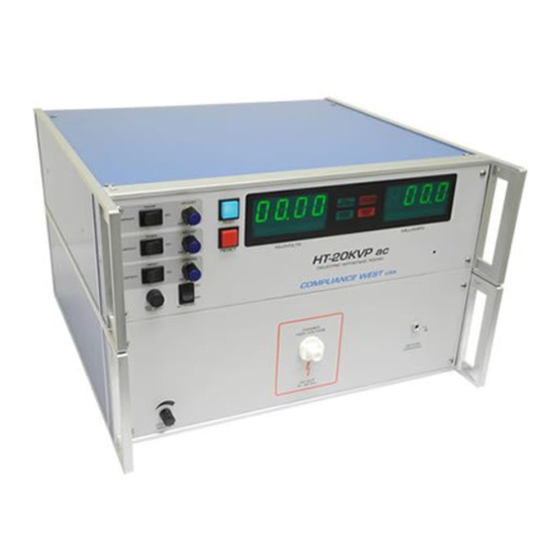
- Page 1 Dielectric Withstand Tester Model HT-20KVPac 0 - 20,000 Volts AC Output...
- Page 3 To fully appreciate all the features of your new meter, we suggest that you take a few moments to review this manual. Compliance West USA stands by your instrument with a full one- year warranty. If the need arises, please don't hesitate to call on Thank you for your trust and confidence.
-
Page 5: Table Of Contents
Table of Contents Quick Start ........................... 1 Initial Setup ........................1 An Introduction to Dielectric Withstand Testing with the HT-20KVPac ........2 Leakage Test........................2 High Voltage Dielectric Withstand Test ................ 2 High Voltage Discharge ....................3 Introduction and Specifications ....................4 Specifications ......................... -
Page 6: Quick Start
Section 1 Quick Start For a quick look at the abilities of the HT-20KVPac, we are providing this quick start page, designed to get you up and running quickly. We recommend that you read the entire manual before using the HT-20KVPac to conduct actual testing. -
Page 7: An Introduction To Dielectric Withstand Testing With The Ht-20Kvpac
Full Voltage indicator is lit to the completion of the test. The Timer Control Switch must be set to ON, or the HT-20KVPac will test only while the Test Button is pressed. The minimum test time is one second regardless of the setting of the Timer Control... -
Page 8: High Voltage Discharge
High Voltage Discharge The HT-20KVPac has an internal circuit designed to remove the high voltage, after completion of the dielectric withstand test. The HT-20KVPac should remain connected to the circuit until the front panel meter shows that the output voltage has dropped to a safe level. -
Page 9: Introduction And Specifications
- Test results are determined quickly, without operator intervention. - The HT-20KVPac allows custom setups for voltage ramp, test time and leakage limit. Your Tester has a warranty for a period of one year upon shipment of the instrument to the... -
Page 10: Specifications
Failure Indication Audible, provided by internal buzzer Visual, provided by red LEDs, on front panel Test can be automatically terminated on failure Leakage Test Provided; 5 mA AC factory set pass/fail point, user adjustable. Table 3-1. HT-20KVPac Specifications... -
Page 11: Operation
The AC Power switch should be turned off while the fuse is being replaced. Front and Rear Panel Features Before using the HT-20KVPac tester, take a few minutes to become familiar with the use of its controls, indicators, and connectors. The front panel features of the HT-20KVPac are... - Page 12 Figure 4-1. Front Panel Controls, Indicators and Connectors...
- Page 13 RAMP ADJUST “Ramp Time Adjust”. For no delay, DEFEAT Ramp Time Switch, Item 3. When lit, indicates that the HT-20KVPac is unarmed. When the RESET button is pressed, the TEST switch is lit. RESET Button PRESSING THE RESET BUTTON AT ANY TIME IMMEDIATELY STOPS TESTING.
-
Page 14: Initial Checkout Procedure
5. Push the RESET button. The TEST button should light. 6. Push the TEST button. 7. The HT-20KVPac tester will conduct a test. The meter will read a voltage, hold, and return to zero. During the test, the voltage can be adjusted using the Voltage Adjustment knob. At the end of the test, the Full Voltage, Hipot Pass, and RESET switch indicators should be lit. -
Page 15: Factory Settings
2 seconds, and the meter will display “d” with the Test Duration set time in seconds. Leakage Current Level Adjust 1. Connect the HT-20KVPac to a correctly rated source of supply and turn ON the tester. 2. Push the RESET button. The TEST indicator should light, indicating that the HT-20KVPac is ready. -
Page 16: Voltage Adjust
Voltage Adjust This procedure controls the high voltage level used in the dielectric withstand test. The HT-20KVPac is factory set for minimum voltage as shipped from the factory. Use the procedure below to set it. 1. Make sure there are no leads connected to the tester. -
Page 17: Setting The Failure Shutdown Switch
Set up tester to correct parameters for unit to be tested using the previously described procedures. 2. Connect the HT-20KVPac to a correctly rated source of supply and turn it on. Plug the black lead into the Return receptacle. Plug the red lead into the Output receptacle. -
Page 18: Test Results
If the Shutdown Limit switch is set to DEFEAT, and the requirements of Table 4-3 are met, the HT-20KVPac will continue to test. Voltage output may sag if the power required by the circuit is beyond the capabilities of the HT-20KVPac. - Page 19 Shutdown Limit Setting: May be set too low. This would cause normal input capacitor charging to draw more that the preset leakage current limit, triggering a Leakage Current Fail light, and terminating the test. Consider raising the acceptable leakage current level; see Adjustment of the Leakage Current Shutdown point.
- Page 20 Full voltage is produced at the output immediately. Test will continue only as long as the TEST button is held in, minimum one second. The HT-20KVPac will NOT shut down on a dielectric failure, but the front panel Hipot Fail light will flash to indicate a dielectric breakdown. The...
-
Page 21: Maintenance And Calibration
Tester. A 1-year calibration cycle is recommended to maintain the specifications given in Section Service Information The HT-20KVPac is warranted to the original purchaser for a period of 1 year. This warranty does not cover problems due to misuse or neglect. -
Page 22: Entering Calibration Mode
ALL ADJUSTMENTS. Entering Calibration Mode NOTE Only enter into this mode if the HT-20KVPac unit needs a re-calibration on any of the parameters of Voltage Meter or Leakage. Turn Off the HT-20KVPac unit. Hold in both the Test and Reset buttons. -
Page 23: Voltage Meter Re-Calibration
Press the Test button and turn up the Voltage Adjust to compare the front meter of the HT- 20KVPac unit vs. the external volt meter, tolerance most be +/-0.1KV full scale. If one value is out of the specified tolerances, the HT-20KVPac unit needs a voltage meter re-calibration. Follow the Voltage Meter Re-Calibration procedure. -
Page 24: Leakage Meter Verification
Press the Test button and slowly turn up the voltage comparing the leakage current on front meter with the external meter. Reading on the external meter should be +/- 0.1mA. If one value is out of the specified tolerances, the HT-20KVPac unit needs a leakage current re-calibration. Follow the Leakage Current Re-Calibration procedure. - Page 25 "L1" again. Select the bottom calibration leakage point by pressing the Reset button until L2 is shown on the front display of the HT-20KVPac unit. Turn the Voltage Adjust on the front panel to minimum. Press the Test button and a leakage number will be displayed on the front panel meter (1.0).
-
Page 26: Technical Assistance
Section 6 Technical Assistance Technical Assistance from Compliance West USA is available: Phone: (800) 748-6224 Hours: 8:30 AM - 4:30 PM Pacific Time. Also available on our web site at: www.compwest.com Contact: Compliance West USA 650 Gateway Center Way, Suite D, San Diego, CA., 92102...
Need help?
Do you have a question about the HT-20KVPac and is the answer not in the manual?
Questions and answers