Table of Contents
Advertisement
Quick Links
Instructions - Parts
Important Safety Instructions.
Read all warnings and instructions in this manual.
Save these instructions.
20 Liter (5 Gallon) Pail Size
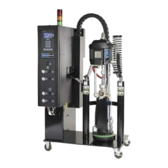
Therm-O-Flow 20
™
EasyKey
Hot Melt Pail Unloaders
For applying hot melt sealant and adhesive
materials.
Maximum Operating Temperature: 400°F (204°C)
Maximum System Air Supply Pressure: 100 psi (0.7 MPa, 7 bar)
NXT 2200 Powered Unloaders
2300 psi (15.9 MPa, 159 bar) Maximum Fluid Working Pressure
100 psi (0.7 MPa, 7 bar) Maximum Air Motor Pressure
NXT 3400 Powered Unloaders
3000 psi (20.7 MPa, 207 bar) Maximum Fluid Working Pressure
82 psi (0.57 MPa, 5.7 bar) Maximum Air Motor Pressure
NXT 6500 Powered Unloaders
3000 psi (20.7 MPa, 207 bar) Maximum Fluid Working Pressure
43 psi (0.29 MPa, 2.9 bar) Maximum Air Motor Pressure
See page 2 for Contents and page 6 for Model Numbers.
Graco Inc. P.O. Box 1441 Minneapolis, MN 55440-1441
Copyright 2007, Graco Inc. is registered to I.S. EN ISO 9001
®
311976 rev.A
TI10076A
Advertisement
Table of Contents
Troubleshooting

Related Manuals for Graco Therm-O-Flow 20 EasyKey NXT 2200


Summary of Contents for Graco Therm-O-Flow 20 EasyKey NXT 2200
- Page 1 43 psi (0.29 MPa, 2.9 bar) Maximum Air Motor Pressure See page 2 for Contents and page 6 for Model Numbers. TI10076A Graco Inc. P.O. Box 1441 Minneapolis, MN 55440-1441 Copyright 2007, Graco Inc. is registered to I.S. EN ISO 9001...
-
Page 2: Table Of Contents
Typical Installation ..... . . 34 Graco Information ......78... -
Page 3: Warnings
Read fluid and solvent manufacturer’s warnings. For complete information about your material, request MSDS from distributor or retailer. • Check equipment daily. Repair or replace worn or damaged parts immediately with genuine Graco replacement parts only. • Do not alter or modify equipment. - Page 4 Warnings WARNING PERSONAL PROTECTIVE EQUIPMENT You must wear appropriate protective equipment when operating, servicing, or when in the operating area of the equipment to help protect you from serious injury, including eye injury, inhalation of toxic fumes, burns, and hearing loss. This equipment includes but is not limited to: •...
- Page 5 Warnings 311976A...
-
Page 6: Overview
Overview Overview How the Therm-O-Flow 20 Works Model Numbers A heated platen melts the sealant or adhesive and The six digit part number stamped on your directs the molten material to the pump inlet. The mate- Therm-O-Flow 20 defines your machine. Each digit rep- rial then travels through a heated Check-Mate pump and resents a component, as shown in the following table. - Page 7 Overview 3. Heat 2. Number of Controls Therm-O-Flow Heat Zones Supply Voltage 4. Pump Ratio 5. Heated 6. Controls 20 (T) (0, 6) (0, 2, 3, 4) (1, 2, 3) Platen (F, S) (0, B, S) Part No. 230 (2) 23:1 (1) Finned (F) Secondary (S)
-
Page 8: Component Identification
Therm-O-Flow system components. See F . 1. • Ram Up/Down Lever (R) changes the direction of Contact your Graco distributor for help in designing a the ram. system to suit your particular needs. • Ram Air Regulators (N, P) control the air pressure The air-powered ram extruder forces high viscosity flu- to the ram. - Page 9 Overview TI10077A TI10076A TI10030A . 1: Component Identification System Bleed-type Master Air Valve Ram Up Air Regulator and Gauge Air Line Filter Ram Down Air Regulator and Gauge Air Motor Air Regulator (bleed-type) and Gauge Ram Up/Down Lever Air Motor Bleed-type Master Air Valve Platen Blow-off Pushbutton Blow-Off Air Regulator and Gauge Heated Pump...
-
Page 10: Power Requirements
Overview Power Requirements Heat Control Zone Selection See Table 1, and the Technical Data on page 77. The Therm-O-Flow 20 has 6 heat zones (see F . 2). • Zones 1 and 2 are always used for the heated Table 1: Electrical Requirements platen and the heated pump. -
Page 11: Installation
Installation Installation Locate and Install the Ram The installation procedure includes: • unpacking the ram 1. Apply 50 psi download pressure to ram. • locating and installing the ram • mechanical setup CAUTION Always lift system at proper lift locations (see F . -
Page 12: Mechanical Setup
Nomex insulation and secure insulation using fiber- trical control panel to a power source. glass tape. 3. Fill displacement pump wet cup 2/3 full with Graco Throat Seal Liquid (TSL). 4. Turn all air regulators to their full counterclockwise position. -
Page 13: Grounding
Installation Grounding Ground the supply unit as instructed here and in the Electrical individual component manuals. Control Panel The power source conduit is not an adequate ground for the system. The unit must be bonded to either the building ground or a true earth ground. To reduce the risk of static sparking, ground the pump, the object being dispensed to, and all other spraying/dispensing equipment used or located in the spraying/dispensing... -
Page 14: Check Resistance
Installation Check Resistance Table 2: RTD Sensor Resistance Zone Component Terminals Range (ohms) Check the Resistance Between the Supply Platen 2011 & 2012 108 +/- 2% Unit and the True Earth Ground Fluid Pump 2051 & 2061 108 +/- 2% Dispense Hose 1 2081 &... -
Page 15: Overview Of The Temperature Controller Settings
3. Select a pail of material that can eliminate the fac- Overview of the Temperature tory-test oil from the system. If necessary, check with Graco or the material supplier for a recom- Controller Settings mended solvent. Temperature controls are set in the Zone Setup screens. -
Page 16: Operator Controls
Operator Controls Operator Controls EasyKey Display and Keypad EasyKey is a simple user interface consisting of an LCD Main Power Disconnect display (A) and keypad (B). See F . 7. Turns system power on or off. Includes system circuit Use to input numerical data, enter Setup screens, scroll breaker. -
Page 17: Lcd Display
Operator Controls Table 4: Key Descriptions Left Arrow: move to previous screen. Right Arrow: move to next screen. System On/Off: on starts system. Activates , and keys. Heat State Toggle: starts heaters in all zones where they are enabled. Cycles through heat states (Heat Off, Heat On/Heat Soak/Run, Setback). -
Page 18: Easykey Display Screens
Power Up Screens Zone Run Screen The Zone Run screen displays a summary of all 6 zones When the EasyKey power switch is turned on the Graco in the system. See F . 9. Logo screen and the phrase “Establishing Communica- tion”... -
Page 19: Setup Mode
EasyKey Display Screens Setup Mode Zone Setup Screens Zone Setup has 2 screens. The screen number appears on the right side of the screen. See F . 11 and F . 12. Entering Setup See Table 5 on page 20 for settings. Press to enter or exit Setup. - Page 20 EasyKey Display Screens Table 5: Zone Setup Screens Screen Setting Selection Description Unloader In single system always A. In tandem or expansion system it is selectable (See F . 11) between A and B. Zone Numeric Enter desired zone (1-6). Zone 1 (platen) and zone 2 (pump) are fixed. All other zones are selectable (hose, gun, regulator, manifold, meter).
- Page 21 EasyKey Display Screens Timer Screen Report Screen Timer settings are explained in Table 6. See also F . 13 The Report screen shows the most recent 12 alarms, and F . 14. with the date and time. Use the Up Arrow or Down Arrow keys to see all the alarms.
- Page 22 EasyKey Display Screens Advanced Screens Advanced Setup has 3 screens. The screen number appears on the right side of the screen. See F . 16 through F . 18, and Table 7 on page 23. The specific gravity listed in the material data sheet may be for solid form at room temperature.
- Page 23 EasyKey Display Screens Table 7: Advanced Setup Screens Screen Setting Selection Description Default Language English, Spanish, Language displayed. English is the default. English (See F . 16) German, French, Japanese, Chinese, custom Number 6 / 6+4 / 6+6 The number of zones in system is set at the factory. Zones (8 / 8+4 / 8+8 are not used on these mod-...
-
Page 24: Setup
Setup Setup Purge Before Using Equipment 3. Slowly turn the ram UP regulator (N) clockwise until the ram begins to rise See. F . 19. The equipment was tested with lightweight oil, which is 4. When the ram is fully raised, install the pail. left in the fluid passages to protect parts. - Page 25 Setup CAUTION Lowering the ram without a pail in place can damage the pail centering guides (if equipped). 11. See F . 19. Slowly turn the ram DOWN regulator (P) clockwise to approximately 5-10 psi (34-69 kPa, 0.3-0.7 bar). The platen will begin to lower into the pail.
-
Page 26: System Heat Up
Setup System Heat Up Prime Pump Never pressurize a hot melt system before turning on In a Tandem system, after a pail change has the heat. The air will be locked from the air motor until occurred on the inactive unloader, pressing the all temperature zones are within a preset window of the temperature set points. - Page 27 Setup 4. Place a waste container under the bleed stem (ST). 8. If the pump does not cycle, adjust the air motor air Using an adjustable wrench, open the bleed stem regulator (C) up by 5 psi (34 kPa, 0.3 bar). Never counterclockwise 1/3 -1/2 turn.
-
Page 28: Prime System
Setup Prime System 3. Place the dispense valve over a waste container. 4. Slowly open the system master air valve. 5. Prime the system until a smooth flow of material dis- penses from the dispense valve. 1. Close the system bleed-type master air valve (A). 6. -
Page 29: Operation
Operation Operation Pressure Relief Procedure 3. Disengage trigger lock. Trigger Lock Disengaged Follow Pressure Relief Procedure when you stop spraying and before cleaning, checking, servicing, or transporting equipment. TI8050A This procedure describes how to relieve pressure for the supply unit. Use this procedure whenever you shut off 4. -
Page 30: Ram Pressure Relief Procedure
Operation Ram Pressure Relief Procedure 5. Exhaust air from both sides of the ram: a. Move the ram UP/DOWN lever to the DOWN position until all air is exhausted from one side of the ram. Follow Pressure Relief Procedure when you stop spraying and before cleaning, checking, servicing, or transporting equipment. -
Page 31: Pail Changing
Operation Pail Changing 1. Place the ram UP/DOWN lever in the UP position. Follow the procedure below to change the pail on a fully heated machine. TI8141A CAUTION 2. Dial ram up regulator pressure to 0 psi. Be sure to reload the empty supply unit with a full pail of material immediately. - Page 32 Operation 4. Push and hold the blow-off air pushbutton (S). The platen will begin to raise. If both unloaders in the system are empty, the pump ready and transition sequence will depend on the unloader to transition to the Run state. ✓...
-
Page 33: System Shutdown
Operation System Shutdown 4. Lock the dispense valve trigger open by pulling and securing the trigger using the trigger retainer TR). Follow the procedure below for normal system shut down, such as at the end of the work day. 1. Make sure the pump rod (PR) is parked in the down position. -
Page 34: Dual Ram Cross-Over Installation
Dual Ram Cross-Over Installation Dual Ram Cross-Over Installation Typical Installation Part No. 15H385 Cross-Over Cable is included with the Dual Ram. Cross-Over Cable TI10075A EasyKey Setup See EasyKey Display and Keypad on page 16. Pail Change Procedure See Pail Changing on page 31. 311976A... -
Page 35: Maintenance
Maintenance Maintenance Periodically (at least once a month), inspect the ram guide sleeves, rods and cylinders for wear or damage. Ground Fault Interrupt Periodically (at least once a month) test the ground fault interrupt switch by pushing the TEST button. Power in a Tandem System In a Tandem System, the secondary unloader pro- vides 24VDC power to the EasyKey display. -
Page 36: Alarm Troubleshooting
Alarm Troubleshooting Alarm Troubleshooting The Therm-O-Flow alarms alert you to a problem and help prevent system shut downs or application errors. If an alarm occurs, operation may stop and the following occurs. • Light Tower Changes (if equipped) • Status bar on the EasyKey Display shows the description •... - Page 37 Alarm Troubleshooting Table 8: Therm-O-Flow Alarms Warnings Cause With optional light tower, the yellow light illuminates and green light remains on if in Run mode. Temperature Warning - occurs when a zone temperature is above/below the setpoint +/- warning deviation speci- fied in the Zone tab of the Setup screen.
-
Page 38: Ram Troubleshooting
Ram Troubleshooting Ram Troubleshooting Problem Cause Solution Ram will not raise or lower. Closed main air valve or clogged air Open air valve; clear air line. line. Not enough ram air pressure. Increase ram air pressure. Worn or damaged ram piston. Replace piston. -
Page 39: Heated Pump Troubleshooting
Heated Pump Troubleshooting Heated Pump Troubleshooting For additional troubleshooting information about the pump, see the pump’s documentation. Problem Cause Solution Rapid downstroke or upstroke (pump Material not heated to proper temper- Check and adjust temperature to cavitation). ature. proper set point. Wait for pump/platen to heat up. -
Page 40: Electrical Control Panel Troubleshooting
Electrical Control Panel Troubleshooting Electrical Control Panel Troubleshooting Problem Cause Solution Disconnect is ON, but EasyKey not The ground fault interrupt has been Have a qualified electrician check lit. activated. wiring. One or more fuses or circuit breakers Have a qualified electrician check tripped. -
Page 41: Service
Service Service Platen Service Whenever you service the ram, follow the Ram Pres- sure Relief Procedure on page 30. Raise the platen up out of the pail before proceed- ing. See Pail Changing on page 31. Periodically (once a month), inspect the ram guide sleeves, rods and cylinders for wear or damage, replace all worn parts. - Page 42 Service Replacing Wiper 1. Follow Pressure Relief Procedure, page 29. 2. Separate the wiper joint, and bend back the strap- ping that covers the clamp (207). F . 22. 3. Unscrew the worm gear and remove the wiper (202). 4. Thread the strapping through the new wiper (202). 5.
-
Page 43: Air Motor/Pump Removal And Service
Service Air Motor/Pump Removal and Service 8. Remove the pump sheet metal enclosure (A). See . 23. a. Remove the cover screws (B). This procedure must be done with the unit still warm. The material and equipment will be hot! b. - Page 44 Service TI10084A . 23 311976A...
-
Page 45: Replacing Heater Bands And Sensors In Pump Module
Service Replacing Heater Bands and Sensors in Pump Module Module heaters and sensor can be serviced without Removing/Replacing RTD Sensor removing the pump module from the supply unit. 1. Turn OFF the main electrical disconnect. Remove the front shrouds. When finished servicing the pump module re-attach shrouds. -
Page 46: Parts
Parts Parts Therm-O-Flow 20 Supply Unit Part Description Part Description 100214 WASHER, lock 277436 CART, assembly 101864 SCREW, cap, socket head; 5/16-18 288544 PEDESTAL, enclosure x 1 in. (25 mm) 253150 CONTROL, standard, 230v, 6 zone 100023 WASHER, plain; 3/8 253154 CONTROL, secondary, 230v, 6 100016 WASHER, lock;... - Page 47 Parts 24, 26, 38 19, 24, 26 7, 8, 9, 10 4 (Ref) TI10078A TI10080A 311976A...
-
Page 48: Pump
Parts Pump Part Description N22LH0 MOTOR, 2200; used on 288506; see 311238 N34LH0 MOTOR, 3400; used on 288507; see 311238 N65LH0 MOTOR, 6500; used on 288508; see 311238 237885 PUMP, Check-Mate; see 308570 15J213 BRACKET, air motor; used on 288506 15J288 BRACKET, air motor;... -
Page 49: Platen
Parts Platen Part Description 288509 PLATE, heated, finned; used on 288511 288510 PLATE, heated, smooth; used on 288512 C31052 HOSE, seal, Mini - 5 207440 VALVE, dispenser 288855 HANDLE, bleed 15J794 ADAPTER, bushing 514930 SCREW, cap, skt hd C31154 CLAMP, worm gear 167730 GASKET, copper 100176 BUSHING, hex 115948 ELBOW, 1/4 npt(m), 5/16 OD tube... -
Page 50: Air Control
Parts Air Control Part Description Part Description C11033 FILTER, air 113269 VALVE, ball, bleed-type; 1/2 npt 120434 SOLENOID, motor 24V dc 113286 VALVE, safety 120435 REGULATOR, remote piloted 115952 VALVE, 4-way, 1/8 npt 15H236 VALVE, ball, female, 1/2 npt 120432 REGULATOR, panel mount C06299 MUFFLER, #10-32 unf 115957 VALVE, check 115948 ELBOW, 1/4 npt(m), 5/16 OD tube... -
Page 51: Easykey Assembly, Part No. 253147
Parts EasyKey Assembly, Part No. 253147 TI7918A TI7919A Back of EasyKey Assembly Part No. Description LABEL, operations 117769 DISPLAY, graphics BOARD, circuit assembly PLATE, blank SCREW, pan head cross 4-40 311976A... -
Page 52: Spare Parts And Kits
Parts Spare Parts and Kits Spare Parts and Kits Graco Part No. Description See manual 308570 Pump Rebuild Kit 253566 Ethernet Kit 253147 EasyKey Display Kit 117769 LCD Graphic Display 253603 Pail Low and Empty Sensors 253547 Light Tower Kit... - Page 53 Parts 311976A...
-
Page 54: Electrical Schematics
Electrical Schematics Electrical Schematics 253150 and 253156 Controls FU 1062 FU 1061 311976A... - Page 55 Electrical Schematics 311976A...
- Page 56 Electrical Schematics 311976A...
- Page 57 Electrical Schematics 1.75 X 3.0 WIRE DUCT INTRF 1.75 X 3.0 WIRE DUCT DISC PARTS AIRFLOW 1.25 X 3.0 WIRE DUCT O O O O O O O O O O O O O O O O O O O O O O O INTRF O O O O O O O O O O O O O O O O O O...
-
Page 58: 253154 And 253160 Controls
Electrical Schematics 253154 and 253160 Controls 1212 1211 FU 1062 FU 1061 311976A... - Page 59 Electrical Schematics 311976A...
- Page 60 Electrical Schematics 1.75 X 3.0 WIRE DUCT INTRF 1.75 X 3.0 WIRE DUCT DISC PARTS AIRFLOW 1.25 X 3.0 WIRE DUCT INTRF O O O O O O O O O O O O O O O O O O O O O O O O O O O O O O O O O O O O O O O O...
-
Page 61: Accessories
Accessories Accessories Light Tower Kit (253547) The optional light tower kit has the following color and flashing lights to signal warnings and alarms. See F Green denotes an active system where the pump will activate when material is needed. Yellow denotes user attention is required. Flashing yellow denotes a pail is empty (when equipped with proximity sensors). -
Page 62: Light Tower Kit Recommended Wire Routing
Accessories Light Tower Kit Recommended Wire Routing EasyKey 1271 1272 TI8541a . 27 311976A... -
Page 63: Pail Low And Empty Sensor Kit (255233)
Accessories Pail Low and Empty Sensor Kit With the optional light tower a yellow light indicates a pail low condition. A flashing yellow light indicates a pail (255233) empty condition. In a tandem system a red light indi- cates both pails are empty. See Light Tower Kit The Pail Low and Empty Sensor Kit is used to indicate (253547), page 61. -
Page 64: Ethernet Kit (253566)
Graco Ethernet Expansion Board (15H816), internal mately 15 MB. Cat 5E patch cord, and the RJ45 panel mount jack. ✓ If the Graco program will not start, check the Web Interface following. Web Interface - allows users to connect, view, and Is the power on? change the setup, log, and error files. - Page 65 Accessories Non-hazardous Area Only Local Network Patch Cable Patch Cable Local Network Connection Direct Connection Laptop PC TI8570A Control Panel Patch Cable . 29 Network Selection 311976A...
- Page 66 Accessories Local Network Hardware and Software Configuration Browser must be closed and restarted for change to be effective. Hardware Patch cables are used to connect each unit to the local network and to the Web connection (A) on the EasyKey panel.
- Page 67 Accessories Software Operation Reports 1. Open Microsoft Internet Explorer. Display material usage report - shows the material pumped from the unit. See F . 33. 2. In the address area type http://192.168.0.1 3. Click Enter. 4. Select yes when security screen appears. 5.
- Page 68 Restore setup values - allows files to be uploaded and restored to the TOF. To change IP settings use the freeware configuration program available from www.lantronix.com/device-net- Software/Resets working/utilities-tools/device-installer.html. Install EasyKey software - downloads the Graco provided software to the PC (approximately 5 minutes). 311976A...
- Page 69 Accessories Ethernet Kit Installation Graco Kit 253566 is required for this connection. Do not operate Therm-O-Flow 20 with electrical control panel doors/covers open. Disconnect power source before servicing or electrically wiring. ti8557 . 39 RJ45 Bulkhead Connector Installation 1. Power the Therm-O-Flow system off and disconnect power source.
-
Page 70: Easykey Modbus / Tcp Wiring Diagram
Accessories EasyKey Modbus / TCP Wiring Diagram TI8761 TI8762 . 41 . 40 . 42 311976A... -
Page 71: Maintenance Call Kit (253548)
Accessories Maintenance Call Kit (253548) The maintenance call kit is designed for the user to indi- cate an issue has occurred and needs to be addressed, but the unit keeps operating if no serious faults have occurred. With the optional light tower kit the mainte- nance call button (E) causes the yellow light to flash making the problem more obvious. -
Page 72: Maintenance Call Kit (253548) Wiring
Accessories Maintenance Call Kit (253548) Wiring ti8559 . 44 311976A... -
Page 73: Discrete I/O Kit (253567)
Accessories Discrete I/O Kit (253567) Preferred Routing The discrete I/O kit is designed to connect to robots or PLC that control the primary unit. This connection allows the communication of System On/Off, Heat On/Heat Soak/Ready, Setback, Pail Empty, Warnings, Alarms, Maintenance, and Gun switch. - Page 74 Accessories No. Signal Description Signal Type Wire Color Digital Input Reference Digital Input Ref Yellow System On/Off Digital Input Brown Heat On/Off Digital Input Pump On/Off Digital Input Orange 24 Vdc from Robot/PLC Digital Input Ref System On/Off Digital Output Green System Run Digital Output...
-
Page 75: Swirl Kit, Part No. 253263
Accessories Swirl Kit, Part No. 253263 TI7921A Air In Ref. Part Description Qty. .125 ID hose barb x 1/4 npt Male brass fitting Regulator Gauge 1/4 to 1/8 Brass Hex Nipple Solenoid Valve 120384 Cable Tube Fitting Nylon tube 3 ft. Socket head cap screw (not shown) Tube Clamp (not shown) Regulator mounting bracket... -
Page 76: Dimensions
Dimensions Dimensions 2.8 in. (7.1 cm) 24.0 in. (61.0 cm) 3.2 in. (8.1 cm) 32.5 in. 22.6 in. (82.6 cm) (57.3 cm) 5.7 in. (14.5 cm) TI7932A 71.0 in. Ram measures 86 in. (180.3 cm) (218 cm) fully extend- ed (highest point. 63.4 in. -
Page 77: Technical Data
Technical Data Technical Data Displacement pump effective area ....1.24 in. (8 cm Volume per cycle ....... 11.7 in. (192 cm Pump cycles per 1 gal. -
Page 78: Graco Standard Warranty
With the exception of any special, extended, or limited warranty published by Graco, Graco will, for a period of twelve months from the date of sale, repair or replace any part of the equipment determined by Graco to be defective.
Need help?
Do you have a question about the Therm-O-Flow 20 EasyKey NXT 2200 and is the answer not in the manual?
Questions and answers