
Related Manuals for Clarke Strong-Arm CFC1000B


Summary of Contents for Clarke Strong-Arm CFC1000B
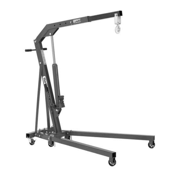
- Page 1 1-TONNE FOLDING CRANE MODEL NO: CFC1000B PART NO: 7611011 ASSEMBLY & USER INSTRUCTIONS ORIGINAL INSTRUCTIONS GC0318 ISS3...
-
Page 2: Technical Specifications
INTRODUCTION Thank you for purchasing this CLARKE Folding Crane. Before attempting to operate the product, it is essential that you read this manual thoroughly and carefully follow all instructions given. In doing so you will ensure the safety of yourself and that of others around you, and you can also look forward to the crane giving you long and satisfactory service. -
Page 3: Safety Precautions
SAFETY PRECAUTIONS Always read instructions before setting up the equipment and before use. Failure to heed these warnings may result in damage to the equipment, or serious personal injury. WORKPLACE SAFETY 1. Always inspect the crane before use to ensure it is correctly assembled and in good condition and replace any damaged or worn parts. - Page 4 Do not substitute any other components or exceed the rated capacity of the crane. 6. If the load capacity decal becomes worn or illegible, contact Clarke Parts and service department, on 0208 988 7400 for replacement. Parts & Service: 020 8988 7400 / E-mail: Parts@clarkeinternational.com or Service@clarkeinternational.com...
-
Page 5: Unpacking And Assembly
Inspect all components to ensure that no damage was suffered in transit. Any deficiencies should be reported to your CLARKE dealer immediately.: 1 x Hydraulic Ram Assembly 2 x Small Wheels... -
Page 6: Tools Required
ASSEMBLY TOOLS REQUIRED Various wrenches of 13,14, 22 & 24 mm will be required or alternatively two adjustable wrenches. 1. Bolt the two larger wheels to the front arms. • Note that bushes are to be fitted inside each wheel. 2. - Page 7 5. Bolt the side brackets to each side of the base frame with a single small bolt. • The 90 mm bolts will be added at the next step. 6. Slide the right arm into the base frame as shown. Line up the holes and secure with a 90 mm bolt, washers and nut, securing the side bracket as you do so.
- Page 8 10. Add the two side braces, bolting them between the base frame and the main support post. Leave the bolts loose until they are aligned with the hole in the main support post. Once aligned, fully tighten the side braces to the base and the support post.
-
Page 9: Purging The Hydraulic System
15. Bolt the hook assembly through the hole on the jib extension using the 90 mm bolt, washer, lock washer and nut. 16. Connect the handle to the rear of the main support post using the two remaining bolts and lock washers. -
Page 10: Operation
OPERATION WARNING: IT IS ESSENTIAL THAT THE ARM LOCKING PINS ARE IN PLACE BEFORE ATTEMPTING ANY LIFTING TASKS. FAILURE TO INSTALL THESE WOULD RESULT IN THE CRANE TIPPING FORWARD WHEN SUBJECTED TO ANY LOAD. RAISING THE JIB IMPORTANT: Make sure that the hook is directly above the point of lift, which in turn is directly above the centre of gravity of the load. - Page 11 STORAGE 1. Remove the bolt and slide the jib extension back to its shortest position. Replace the bolt to secure the jib. 2. Release the control valve to lower the jib assembly to its lowest position. 3. Pull out the ‘R’ clip, which secures the each arm locking pin, then pull out the lock pin.
-
Page 12: Maintenance
3. Do not attempt to adjust or tamper with the ram assembly, there are no user-serviceable parts. Contact your Clarke service department for any servicing. 4. Always visually inspect the crane before use, to ensure that all parts are correctly located and secure. - Page 13 NOTE: Top up using Clarke hydraulic oil (part number 3050830). • Do not mix different types of oil. GUARANTEE This CLARKE product is guaranteed against faulty manufacture for a period of 12 months from the date of purchase. Please keep your receipt as proof of purchase.
- Page 14 PARTS DIAGRAM - FRAME ASSEMBLY Parts & Service: 020 8988 7400 / E-mail: Parts@clarkeinternational.com or Service@clarkeinternational.com...
- Page 15 PARTS LIST- FRAME ASSEMBLY PART NO DESCRIPTION PART NO DESCRIPTION Bolt Bolt Bush Flat Washer Large Wheel Bolt Spring Washer Spring Washer Right Arm Ram Assembly Left Arm Side Brace Small Wheel Main Upright Bolt Spring Washer Spring Washer Bolt Handle Grip Locking Pin Handle Bar...
- Page 16 PARTS DIAGRAM - RAM ASSEMBLY Parts & Service: 020 8988 7400 / E-mail: Parts@clarkeinternational.com or Service@clarkeinternational.com...
- Page 17 PARTS LIST - RAM ASSEMBLY PART NO DESCRIPTION PART NO DESCRIPTION O-Ring Socket Head Cap Screw Top Nut Copper Washer Sealing Ring Valve Body Outer Sleeve O-ring Oil Plug Large Cylinder Sealing Ring O-ring Piston Rod Retaining Seal Circlip Big Pump Plunger Sealing Ring Handle Socket Wire Ring...
-
Page 18: Declaration Of Conformity
DECLARATION OF CONFORMITY Parts & Service: 020 8988 7400 / E-mail: Parts@clarkeinternational.com or Service@clarkeinternational.com... - Page 19 FURTHER CLARKE PRODUCTS Parts & Service: 020 8988 7400 / E-mail: Parts@clarkeinternational.com or Service@clarkeinternational.com...
Need help?
Do you have a question about the Strong-Arm CFC1000B and is the answer not in the manual?
Questions and answers