
Subscribe to Our Youtube Channel
Related Manuals for Clarke CCM125P


Summary of Contents for Clarke CCM125P
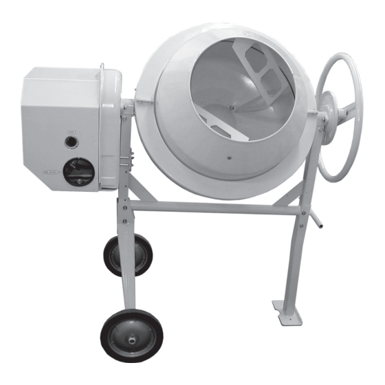
- Page 1 CEMENT MIXER CEMENT MIXER Model CCM125P Part No. 3400820 1005 OPERATING & MAINTENANCE INSTRUCTIONS...
- Page 2 Please read this manual in conjunction with the Engine Handbook © Copyright CLARKE International. All rights reserved. March, 2001...
-
Page 3: Table Of Contents
GUARANTEE This CLARKE product is guaranteed against faulty manufacture for a period of 12 months from the date of purchase. Please keep your receipt as proof of purchase. This guarantee is invalid if the product is found to have been abused or tampered with in any way, or not used for the purpose for which it was intended. -
Page 4: General Safety Precautions
GENERAL SAFETY RULES WARNING: As with all machinery, there are certain hazards involved with their operation and use. Exercising respect and caution will considerably lessen the risk of personal injury. However, if normal safety precautions are overlooked or ignored, personal injury to the operator or damage to property may result. -
Page 5: Unpacking & Pre-Assembly
Remove all components from the packing cases and lay them out neatly so that they may be identified and checked for any possible damage during transit. Should any component be found to be damaged, please contact your Clarke dealer immediately. -
Page 6: Assembly
ASSEMBLY NOTE: 1. Letters in brackets refer to Fig.1 2. Unless otherwise stated, all nuts, bolts, washers and fixings are supplied. IMPORTANT For maximum safety and to ensure the adjustments are carried out correctly, assistance should be employed during the assembly operation. 1. - Page 7 3. The Hand Wheel & Fittings 3.1 Slide the Locking Plate (F), over the large diameter shaft, at the leg end of the frame, with the rim facing inwards, as shown in Fig.4. (Note that the hole in the Plate is ‘notched’. This is to allow the plate to slide over the lugs of the circlip on the shaft).
- Page 8 5. The Upper Drum Note: Before bolting down the upper drum section, it is necessary to perform a ‘dry run’ in order to determine the correct orientation, to ensure all components are correctly aligned. 5.1. With assistance, lower the upper drum section on to the lower drum. Rotate it until the position is found where the mixing blade upper mounting holes line up with the corresponding square holes in the upper drum section, and the holes in the rims of the two drum sections also become aligned.
- Page 9 6.3 Thread on a spring washer and nut, but DO NOT tighten the nuts at this stage 6.4 When all four bolts are fitted, centralise the Fig.8 Inner Cover (K) about its mountings, then fully tighten the two bolts securing it to the Bearing Block (X).
- Page 10 8. Fitting the Drive Belt NOTE: It is now most important that the motor pulley be aligned so that it is directly in line with the driven pulley (J). 8.1 A piece of 6mm rod is provided which is used to align the pulleys as follows: Fig.11 Hold the rod firmly in the ‘Vee’...
-
Page 11: General Information
9. Fitting the Drum Collar Before the collar is attached, it is strongly recommended that a layer of grease (not supplied) be applied to the underside of the serrated rim of the lower drum. Fig.12 9.1 Secure each half of the collar to the side brackets first. -
Page 12: Maintenance
MAINTENANCE - General Before each use Inspect the machine to ensure it is not damaged and will perform its normal functions correctly. If any damage is apparent, have it fixed before putting into service. Periodically Inject a few drops of light oil into the oil points, located on top of the Bearing Blocks and rotate the drum to ensure distribution of oil within the bearing surface. -
Page 13: Specifications
Part Number ..............3400820 SPARE PARTS & SERVICE CONTACTS Please contact your nearest dealer, or CLARKE International, on one of the following numbers. PARTS & SERVICE TEL: 020 8988 7400 PARTS & SERVICE FAX: 020 8558 3622 e-mail as follows: PARTS: Parts@clarkeinternational.com... -
Page 14: Parts List And Diagram
PARTS DIAGRAM... - Page 15 SD0042 The following items are the nuts bolts and washers packed separately and which may be locally procured from any Hardware or DIY store, or from your CLARKE dealer quoting the part numbers given. M5 x 10 Slot Rd Hd...
Need help?
Do you have a question about the CCM125P and is the answer not in the manual?
Questions and answers