
Related Manuals for Clarke Contractor CCM125D


Summary of Contents for Clarke Contractor CCM125D
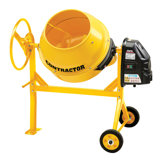
- Page 1 125L CEMENT MIXER MODEL NO: CCM125D PART NO: 3400841 OPERATION & MAINTENANCE INSTRUCTIONS ORIGINAL INSTRUCTIONS GC0620 - ISS 1...
-
Page 2: Specification
INTRODUCTION Thank you for purchasing this CLARKE Cement Mixer. Before attempting to use this product, please read this manual thoroughly and follow the instructions carefully. In doing so you will ensure the safety of yourself and that of others around you, and you can look forward to your purchase giving you long and satisfactory service. - Page 3 6. NEVER stand on the machine. Injury could occur from a fall. 7. ALWAYS store machines out of reach of children. 8. ALWAYS read and become familiar with the entire operating manual. 9. NEVER allow persons unfamiliar with this manual to operate this machine. 10.
- Page 4 SAFETY SYMBOLS DISPLAYED ON THE MIXER Read instruction Wear eye protection. manual before use. Wear protective Wear protective gloves. footwear. Wear ear protection. Protect the environment when emptying. Do not use where the Keep bystanders at a mixer could tip over. safe distance.
-
Page 5: Electrical Connections
ELECTRICAL CONNECTIONS WARNING: READ THESE ELECTRICAL SAFETY INSTRUCTIONS THOROUGHLY BEFORE CONNECTING THE PRODUCT TO THE MAINS SUPPLY. Connect the mains lead to a standard, 230 Volt (50Hz) electrical supply through an approved 13 amp BS1363 plug, or a suitably fused isolator switch. If the plug has to be changed because it is not suitable for your socket or because of damage, it must be removed and a replacement fitted, following the wiring instructions shown below. - Page 6 Remove all components from the packing and lay them out so that they can be identified and checked for any damage in transit. Should any item be damaged or missing, please contact your CLARKE dealer immediately. 1 x Tilt Handwheel...
- Page 7 ASSEMBLY 1. Bolt the main frame to the axle frame using M8 x 70mm bolts & nuts supplied. 2. Bolt the support stand to the main frame using M8 x 70mm bolts and nuts. (Fixings packs B and C) 3. Slide the flat washers onto the axles, followed by a wheel and a second flat washer.
- Page 8 7. Fit the angle adjusting plate to the bearing housing opposite the drive spindle end. Slide it over the cradle spindle and bolt it to the bearing housing with two M8 x 25mm bolts. (Fixing pack G). 8. Insert the return spring into the sleeve on the tilt handwheel and slide the handwheel onto the cradle spindle.
- Page 9 13. With the drive assembly in position, re-fit the cover and secure with the 6 self-tapping screws. 14. Using the X-head screws, rubber washers, flat washers and M8 nuts, loosely fit the blades to the upper drum, noting that the tapered end will be at the bottom of the drum.
-
Page 10: Operation
OPERATION 1. Switch the mixer on by pressing the green (I) switch on the motor. Stop by pressing the red (O) switch. 2. Introduce water first, to prevent the mixer from clogging. 3. Add cement as required. 4. Add aggregate to suit. •... -
Page 11: Care And Maintenance
CARE AND MAINTENANCE BEFORE STARTING WORK Inspect the power cable and ensure it is free from damage and is not in danger of being damaged by vehicles, equipment or other operations taking place on the work site. AFTER USE At the end of the working shift it is essential that the machine is hosed down thoroughly with clean water, being sure to remove all traces of the cement mix especially from around the mixing blades. -
Page 12: Environmental Recycling Policy
MAINTENANCE FREE ITEMS The bearings in the machine are sealed for life and require no maintenance. The drive belt is under constant tension and therefore no adjustment is required. ENVIRONMENTAL RECYCLING POLICY By purchasing this product, the customer is taking on the obligation to deal with its safe disposal in accordance with the Waste Electrical and Electronic Equipment (WEEE). -
Page 13: Declaration Of Conformity
DECLARATION OF CONFORMITY Parts & Service: 020 8988 7400 / E-mail: Parts@clarkeinternational.com or Service@clarkeinternational.com... -
Page 14: Parts Diagram
PARTS DIAGRAM Parts & Service: 020 8988 7400 / E-mail: Parts@clarkeinternational.com or Service@clarkeinternational.com... -
Page 15: Parts List
PARTS LIST DESCRIPTION DESCRIPTION DESCRIPTION X-head screw M8x20 27 Spring 53 Power cable Waterproof washer 28 Tipping wheel 54 Strain relief nut Flat washer 8 29 Flat washer 10 55 Strain relief rubber Spring washer 8 30 n/a 56 Strain relief bolt Nut M8 31 Nut M10 57 Strain relief nut...
Need help?
Do you have a question about the Contractor CCM125D and is the answer not in the manual?
Questions and answers