Table of Contents
Advertisement
Quick Links
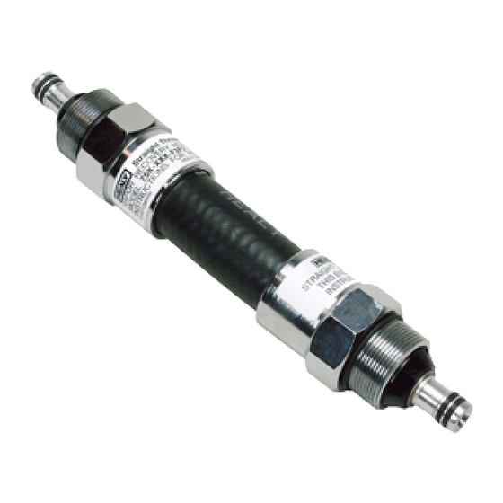
Healy Model 8701VV Breakaway
35 to 70 foot pounds. Be sure the vapor tube fitting slides easily into
item 2 before final tightening.
install the secondary hose and tighten to 35 to 70 foot pounds. Be sure
the vapor tube fitting slides easily into item 3 before final tightening.
6-1
CARB Approved IOM 6 - Healy Breakaway Model 8701VV - Executive Orders VR-201 and VR-202
Advertisement
Table of Contents

Related Manuals for Franklin Fueling Systems Healy 8701VV


Summary of Contents for Franklin Fueling Systems Healy 8701VV
- Page 1 Healy Model 8701VV Breakaway 35 to 70 foot pounds. Be sure the vapor tube fitting slides easily into item 2 before final tightening. install the secondary hose and tighten to 35 to 70 foot pounds. Be sure the vapor tube fitting slides easily into item 3 before final tightening. CARB Approved IOM 6 - Healy Breakaway Model 8701VV - Executive Orders VR-201 and VR-202...
- Page 2 DRIVE-OFF BREAKAWAY RECONNECTION PROCEDURE Use this procedure to either reconnect or disconnect (reverse order) the Healy 8701VV Breakaway as part of Section 1.4 Procedure for Reconnecting Breakaway and Testing Fueling Point after Drive-Off in the Assist Systems Scheduled Maintenance. NOTE: Breakaway Reconnections must be logged in the GDF Maintenance Log.
- Page 3 Dowel Guide Top Clamp Shear Pin Bushing Hole Dowel Pin Shear Pin Installation Spare Shear Tool Grip Bottom Clamp Franklin Fueling Systems Website: http://www.franklinfueling.com 3760 Marsh Road Email: sales@franklinfueling.com Madison, Wisconsin 53718 USA Telephone: 800-225-9787 ARB Approved Installation, Operation and Maintenance Manual...
-
Page 4: Tools Needed
II. EASYGRIP BREAKAWAY RECONNECTION CLAMP TOOLS NEEDED: • EasyGrip Reconnection Clamp • 8 mm Hex Head Socket • Torque wrench • Safety Glasses RECONNECTION PROCEDURE NOTE: Additional information on the EasyGrip operation can be found by viewing a video clip on their website at http://www.simplegrip123.com/ Inspect each half of the separated breakaway for obvious damage to the outer-shell, plastic... - Page 5 After completing inspection, lightly lubricate the main o-ring on the top half of the breakaway (See Figure 1). Any weight motor oil is acceptable. With the EasyGrip in its full open position, place the top portion of the breakaway into the top side of the EasyGrip and the bottom portion of the breakway into the bottom side (See Figure 2).
- Page 6 Align the dowel pin in the bottom half of the breakaway with the dowel pin guide located in the top half of the breakaway. When the dowel pin and guide are aligned, continue squeezing tool grips until the breakaway halves come together. See Figure 4 Figure 4 CAUTION: Reconnection can cause a small amount of gasoline to leak out of the breakaway.
- Page 7 Torque the shear pin to 20 inch-pounds (~ 1.5 ft-lbs). DO NOT OVER-TIGHTEN If available, install a shear pin (#787) in the spare shear pin location. Remove the Easygrip. Proceed with the tests outlined in Section 1.4 of the Healy Systems Scheduled Maintenance. CARB Approved IOM 6 - Healy Breakaway Model 8701VV - Executive Orders VR-201 and VR-202...
- Page 8 Healy Model 807 Swivel Breakaway 35 to 70 foot pounds. Be sure the vapor tube fitting slides easily into the nozzle before final tightening. hose. Tighten to 35 to 70 foot pounds. Be sure the valve and spring (items 6 & 11) are in place before final tightening. CARB Approved IOM 6 - Healy Breakaway Model 807 Swivel - Executive Orders VR-201 and VR-202...
- Page 9 DRIVE-OFF BREAKAWAY RECONNECTION PROCEDURE Use this procedure to either reconnect or disconnect (reverse order) the Healy 807 Swivel Breakaway as part of Section 1.4 Procedure for Reconnecting Breakaway and Testing Fueling Point after Drive- Off in the Healy Systems Scheduled Maintenance. TOOLS NEEDED: •...
- Page 10 Remove the shear pin (#787-1) located in the spare shear pin location of the breakaway and install in place of the original. Torque the shear pin to 20 inch-pounds (~ 1.5 ft-lbs). DO NOT OVER-TIGHTEN. If available, install a shear pin (#787-1) in the spare shear pin location. Remove the Breakaway Reconnection Clamp.
- Page 11 Franklin Fueling Systems Website: http://www.franklinfueling.com 3760 Marsh Road Email: sales@franklinfueling.com Madison, Wisconsin 53718 USA Telephone: 800-225-9787 ARB Approved Installation, Operation and Maintenance Manual Fax: 608-838-6433 CARB Approved IOM 6 - Healy Breakaway Model 807 Swivel - Executive Orders VR-201 and VR-202...
- Page 12 Recommended Instructions Installation, Maintenance, Inspection 577014-071 CATLOW CTMCA Breakaway DATE 03/2016 VERY IMPORTANT READ THIS BEFORE INSTALLING YOUR BREAKAWAY WARNING: USE ONLY ON SYSTEMS RATED AT 50 PSI MAXIMUM USE ON SYSTEMS HAVING HIGHER STATIC PRESSURE MAY CAUSE PEMATURE SEPARATION ALWAYS CHECK FOR ELECTRICAL CONTINUITY FOLLOWING PETROLEUM EQUIPMENT INSTITUTE (PEI) RECOMMENDED TEST PROCEDURE (PEI/RP400-02) PRIOR TO INSTALLATION: Refer to the model of breakaway for the maximum pull force before you proceed with the instructions...
- Page 13 577014-071 Recommended Instructions DATE 03/2016 CAM TWIST MAGNETIC BREAKAWAY Model: CTMCA IF SEPARATION OCCURS Isolate/turn off dispenser, relieve line pressure from the whip hose and the nozzle hose. Drain fuel into an approved metal container. 2. Inspect the entire system for damage and/or leaks. Replace any damaged components in the system (PEI/RP500-11 9.2.2). Clean the magnet surfaces on both the male and female couplings and inspect for damage.
-
Page 14: Repair Kit
O-Ring REPAIR KIT Instructions 577014-071 DATE 03/2016 CAMTWIST Magnetic Breakaway Isolate fuel pressure/flow from the system. If dispenser is off and depressurized, o-rings can be safely replaced WITHOUT draining the hose assembly. Always lubricate o-rings before installing and reconnecting. An o-ring pick or small stiff wire will be useful to remove old o-rings. CTMCA O-RING REPLACEMENT The CTMCA has four (4) O-rings that can be serviced or replaced in the field. -
Page 15: Equipment Warranty
CAMTWIST Magnetic Breakaway 577014-071 DATE 03/2016 Warranty EQUIPMENT WARRANTY Veeder-Root warrants that this product shall be free from defects in material and workmanship and is compliant with all applicable performance standards and specifications for which it has been certified, for a period of one (1) year from date of installation when proof of the date of install is provided. -
Page 16: General Information
VST Installation Procedure for Vapor Systems Technologies, Inc. 650 Pleasant Valley Drive Phase II EVR Vacuum Assist Springboro, Ohio 45066 (USA) Safety Breakaway Devices Toll Free: 1-888-878-4673 Phone: 937-704-9333 Part Number Series: VST-HEVR-SBK; Fax: 937-704-9443 VST-ISVR-SBK www.vsthose.com APPLICATION Figure 1. These VST Safety Breakaway devices are intended to prevent damage to the EVR Vacuum Assist Hanging Hardware dispenser and hose in the event of a vehicle drive off. - Page 17 VST Installation Procedure for Vapor Systems Technologies, Inc. 650 Pleasant Valley Drive Phase II EVR Vacuum Assist Springboro, Ohio 45066 (USA) Safety Breakaway Devices Toll Free: 1-888-878-4673 Phone: 937-704-9333 Part Number Series: VST-HEVR-SBK; Fax: 937-704-9443 VST-ISVR-SBK www.vsthose.com 4. Tighten breakaway connection to 50 ft.-lbs. of torque. DO NOT OVER 7.
-
Page 18: Maintenance
VST Installation Procedure for Vapor Systems Technologies, Inc. 650 Pleasant Valley Drive Phase II EVR Vacuum Assist Springboro, Ohio 45066 (USA) Safety Breakaway Devices Toll Free: 1-888-878-4673 Phone: 937-704-9333 Part Number Series: VST-HEVR-SBK; Fax: 937-704-9443 VST-ISVR-SBK www.vsthose.com 13. After the two breakaway halves are properly snapped together, remove the 5.
Need help?
Do you have a question about the Healy 8701VV and is the answer not in the manual?
Questions and answers