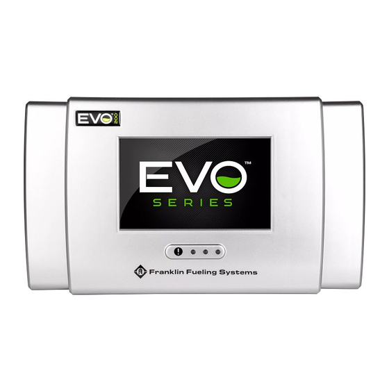
Franklin Fueling Systems EVO 200 Replacement Manual
Input board
Hide thumbs
Also See for EVO 200:
- Programming manual (54 pages) ,
- Operation manual (44 pages) ,
- Installation manual (24 pages)
Advertisement
Quick Links
Advertisement

Summary of Contents for Franklin Fueling Systems EVO 200
- Page 1 200 AND EVO 400 INPUT BOARD REPLACEMENT GUIDE...
- Page 2 Copyright © 2019 Franklin Fueling Systems, LLC, Madison, WI 53718. All world rights reserved. No part of this publication may be stored in a retrieval system, transmitted, or reproduced in any way, including, but not limited to, photocopy, photograph, magnetic, or other record, without the prior written permission of Franklin Fueling Systems.
-
Page 3: Table Of Contents
Contents Introduction ............................1 Questions and concerns ........................1 Conventions used in this manual ....................1 Operating precautions ........................1 Certified installer or service person ....................2 Required tools ..........................2 Replacing the Input Board ........................3... -
Page 5: Introduction
Introduction This manual contains instructions for replacing the input board on the Franklin Fueling Systems (FFS) EVO 200 and EVO 400 Automatic Tank Gauges (ATGs). You must follow all safety information, warnings, instructions, and other information in this manual. Please read this entire manual carefully. -
Page 6: Certified Installer Or Service Person
CAUTION: Use only original FFS parts. Substituting non-FFS parts could cause the device to fail, which could create a hazardous condition and/or harm the environment. WARNING: Follow all codes that govern how you install and service this product and the entire system. -
Page 7: Replacing The Input Board
Replacing the Input Board IMPORTANT: Make sure you wear a grounding strap during this entire procedure. If you do not, your EVO 200 or EVO 400 ATG could be permanently, severely damaged, and your warranty could be voided. IMPORTANT: Lift the cover away carefully to help avoid damaging the LED light pipes. WARNING: Your ATG has more than one power connection point. - Page 8 3. Press in one of the side tabs on the display until it is disengaged, and then press in the other side tab. Flip the LCD display down when both side tabs are disengaged. IMPORTANT: Put the 2-pin stacker display ground you remove in the following step in a safe place.
- Page 9 IMPORTANT: In the following step, your large, white ribbon cable connector may not have the latches shown. Be extremely careful and gentle when you remove this cable. The connector is very delicate. If you break it, you must replace the entire main circuit board. 6.
- Page 10 9. Pivot the display assembly until the other hinge tab is disengaged, and then lift out the display assembly. 10. Remove the WiFi antenna (if present). 11. Use two 5/16" (8 mm) wrenches to remove the WiFi antenna connector. 12. Use a Phillips screwdriver to remove the Phillips screws in each of the four corners of the main board.
- Page 11 IMPORTANT: In the following step, make sure you gently remove the 23-pin board stacker to avoid deforming it. 15. Use both hands to gently pull the 23-pin board stacker strait up. You must lift both sides of the stacker evenly to avoid deforming it. Place the stacker in a safe location when you have removed it.
- Page 12 18. Lift the input board out of the console. 19. Lower the new input board gently into the console so that the holes for the standoffs and Phillips screws are aligned. Start securing the board from the lower left screw, which is smaller in diameter and serves as a pilot hole.
- Page 13 24. Use two 5/16" (8 mm) wrenches to install and tighten (do not overtighten) the WiFi antenna connector. 25. Reinstall the WiFi antenna (if you have one). 26. Insert the left or right hinge tab on the replacement LCD display assembly in its corresponding hinge hole.
- Page 14 28. Connect the 4-pin ribbon cable to the TOUCH SCREEN connector. IMPORTANT: In the following step, your large, white ribbon cable connector may not have the latches shown. Be extremely careful and gentle when you connect this cable. The connector is very delicate.
- Page 15 31. Insert the 2-pin stacker display ground (that you removed earlier) into the J-18 connector, Make sure you insert it into the holes that are closest to the center of the main circuit board. 32. Flip the display up, and press in the latches on the display holder so that they click into their holes in the barriers.
- Page 16 228180039 r1...


Need help?
Do you have a question about the EVO 200 and is the answer not in the manual?
Questions and answers