
Related Manuals for FLIR FIREFLY


Summary of Contents for FLIR FIREFLY
- Page 1 INSTALLATION GUIDE FLIR FIREFLY® Version 1.1 Revised 6/27/2019 Copyright © 2015-2019 FLIR Integrated Imaging Solutions Inc. All rights reserved.
- Page 2 Hardware Warranty The warranty for the Firefly camera is 3 years. For detailed information on how to repair or replace your camera, please see the terms and conditions on our website.
-
Page 3: Table Of Contents
3.2 Installing Your Interface Card and Software 3.3 Installing Your Firefly 3.4 Powering Your Firefly 4 Tools to Control your Firefly 4.1 Using the Spinnaker® Software Development Kit 4.1.1 SpinView Camera Evaluation Application 4.1.2 Custom Applications Built with the Spinnaker API 4.2 Using GenICam Applications... - Page 4 7.1 General Purpose Input/Output (GPIO) 7.2 GPIO Electrical Characteristics 7.3 Input Timing Characteristics 7.4 Output Timing Characteristics 8 Troubleshooting 8.1 Support 8.2 Status Indicator LED Contacting Us Revision History 6/27/2019 ©2015-2019 FLIR ® FLIR Firefly Installation Guide Integrated Imaging Solutions Inc. All rights reserved.
-
Page 5: Firefly Installation Guide
1 Firefly Installation Guide Firefly Installation Guide Welcome to the Firefly camera. We offer a number of resources to assist you with the Firefly. Spinnaker SDK—software development kit that provides GenICam-compliant controls to create applications for the camera. Spinnaker is available for download. Each installation includes API documentation for C, C++, and C#. -
Page 6: Handling Precautions And Camera Care
2 Handling Precautions and Camera Care Handling Precautions and Camera Care Your FLIR machine vision camera is a precisely manufactured device and should be handled with care. Here are some tips on how to care for the device. Avoid electrostatic charging. -
Page 7: Firefly Installation
Lens Mounting Tripod adapter (optional) (see Mounting) Interface card (see Interface Card) FLIR sells a number of the additional parts required for installation. To purchase, visit the Accessories page. Have you visited the FLIR website? FLIR machine vision products page has many resources to help you operate your camera effectively, including: ®... -
Page 8: Installing Your Interface Card And Software
3 Firefly Installation To access these resources: 1. Go to FLIR machine vision. 2. Click on your product family. 3. Click on Go to Support Page. Overview tab - links to software, knowledge base articles, and application notes. Resources tab - links to camera references, technical references, getting started manuals, imaging performance results, drawings, PCNs, firmware, and software. -
Page 9: Installing Your Firefly
3 Firefly Installation f. After download is complete, open the file to start the Spinnaker setup wizard. g. Follow the steps in each setup dialog. Installing Your Firefly 1. Install the Tripod Mounting Bracket (optional) The ASA and ISO-compliant tripod mounting bracket attaches to the camera using the included screws. - Page 10 3 Firefly Installation The camera does not transmit images for the first 100 ms after power-up. The auto-exposure and auto-white balance algorithms do not run while the camera is powered down. It may therefore take several images to get a satisfactory image.
-
Page 11: Tools To Control Your Firefly
4 Tools to Control your Firefly Tools to Control your Firefly The Firefly's features can be accessed using various controls, including: Spinnaker SDK including API examples SpinView camera evaluation application, included in the Spinnaker SDK installation Third-party GenICam applications ®... -
Page 12: Using Genicam Applications
4 Tools to Control your Firefly Using GenICam Applications USB3 Vision is a communication interface for vision applications based on the USB 3.0 technology. All cameras supporting USB3 Vision interact the same way with software also supporting USB3 Vision. For more information on the standard, visit visiononline.org. -
Page 13: Configuring Firefly Setup
5 Configuring Firefly Setup Configuring Firefly Setup After successful installation of your camera and interface card, you can make changes to the setup. Use the tools described below to change the driver for your interface card. For information on updating your camera's firmware post installation, see Camera Firmware. -
Page 14: Camera Firmware
5 Configuring Firefly Setup Camera Firmware Firmware is programming that is inserted into the programmable read-only memory (programmable ROM) of most FLIR cameras. Firmware is created and tested like software. When ready, it can be distributed like other software and installed in the programmable read-only memory by the user. -
Page 15: Firefly Physical Interface
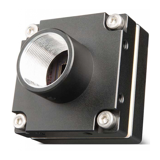
6 Firefly Physical Interface Firefly Physical Interface Firefly Physical Description 1. General purpose I/O connector 4. Mounting holes General Purpose Input/Output (GPIO) See Mounting 2. Status LED 5. Lens mount Status Indicator LED Lens Mounting 3. Interface connector 6. Glass/IR filter system Interface connector... -
Page 16: Firefly Dimensions
6 Firefly Physical Interface Firefly Dimensions Note: To obtain 3D models, go to your product's support page from FLIR machine vision or contact Support. Firefly Dimensional Drawing Interface Connector 6.3.1 USB 3.1 Connector The camera is equipped with a USB 3.1 Micro-B connector that is used for data transmission, camera control and power. -
Page 17: Interface Cables
Interface Cables To purchase a recommended cable from FLIR, visit the Products Accessories page. For USB3 cameras—The USB3 standard does not specify a maximum cable length. FLIR sells a number of cable options. Visit the Product Accessories page for more information. -
Page 18: Interface Card
6 Firefly Physical Interface Interface Card To purchase a compatible card from FLIR, visit the Products Accessories page. The camera must connect to an interface card. This is sometimes called a host adapter, a bus controller, or a network interface card (NIC). -
Page 19: Lens Mounting
6 Firefly Physical Interface Lens Mounting Lenses are not included with individual cameras. Related Knowledge Base Articles Selecting a lens for your camera 6.9.1 Back Flange Distance The Back Flange Distance (BFD) is offset due to the presence of both a 1 mm infrared cutoff (IRC) filter and a 0.5 mm sensor package window. - Page 20 6 Firefly Physical Interface Related Knowledge Base Articles Removing the IR filter from a color camera Selecting a lens for your camera 6/27/2019 ©2015-2019 FLIR ® FLIR Firefly Installation Guide Integrated Imaging Solutions Inc. All rights reserved.
-
Page 21: Input/Output Control
Measurement conditions: Opto-Isolated I/O VCC=5 V, Rext=1 KOhm, Non-Isolated Output: VCC=5 V, Rext=330 Ohm, Non-Isolated Input: VCC=3.3 V. Measured over operating temperature range (-20°C to +50°C ambient temperature), unless otherwise noted. 1—GPIO cable assembly wire colors 2—Dual function pin 6/27/2019 ©2015-2019 FLIR ® FLIR Firefly Installation Guide Integrated Imaging Solutions Inc. All rights reserved. -
Page 22: Gpio Electrical Characteristics
6 mA 12 V 2.4 kΩ 5 mA 24 V 4.7 kΩ 5.2 mA 30 V 4.7 kΩ 6.5 mA Values are for reference only 6/27/2019 ©2015-2019 FLIR ® FLIR Firefly Installation Guide Integrated Imaging Solutions Inc. All rights reserved. - Page 23 7 Input/Output Control Non-isolated input and output circuit 6/27/2019 ©2015-2019 FLIR ® FLIR Firefly Installation Guide Integrated Imaging Solutions Inc. All rights reserved.
-
Page 24: Input Timing Characteristics
Input Threshold High Voltage 4.54 V Input Threshold Low Voltage 1.26 V Cycle Rise Time 10.8 μs Cycle Fall Time 2 μs Current 4.1 mA 6/27/2019 ©2015-2019 FLIR ® FLIR Firefly Installation Guide Integrated Imaging Solutions Inc. All rights reserved. -
Page 25: Output Timing Characteristics
Output Threshold High Voltage 4.48 V Output Threshold Low Voltage 0.7 V Cycle Rise Time 2.6 μs Cycle Fall Time 0.23 μs Opto Current 4.8 mA 6/27/2019 ©2015-2019 FLIR ® FLIR Firefly Installation Guide Integrated Imaging Solutions Inc. All rights reserved. -
Page 26: Troubleshooting
8 Troubleshooting Troubleshooting Support FLIR endeavors to provide the highest level of technical support possible to you. Most support resources can be accessed through your product's Support page. From the FLIR machine vision page, click on your product family and then click the Go to Support Page link. -
Page 27: Status Indicator Led
Blinking Green (2 blinks) USB2 Blinking Green (3 blinks) USB3 Solid Green Acquisition Started Rapid Flashing Green Firmware update in progress Flashing Green and Red General Error 6/27/2019 ©2015-2019 FLIR ® FLIR Firefly Installation Guide Integrated Imaging Solutions Inc. All rights reserved. -
Page 28: Contacting Us
For any questions, concerns or comments please contact us via the following methods: Email General questions Support Ticket Technical support Go to the Support Page for any product on the FLIR machine Chat vision page and click the chat icon Find specifications, support articles, downloads on the Website product page at FLIR machine vision...
Need help?
Do you have a question about the FIREFLY and is the answer not in the manual?
Questions and answers