Advertisement
Quick Links
3 mm hex
key
For installations that are using the Concealed Cable Mounting Arm,
refer to the installation manual for instructions:
FLIR FC-Series S Installation Manual (427-0073-11-12)
Caution!
Except as described in this guide, do not disassemble the FC-Series S camera.
Damage to the camera can occur as the result of careless handling or
electrostatic discharge (ESD).
Prior to making any connections, ensure the power is switched off.
Note
Power: Power Over Ethernet (PoE) or 12-40VDC, 24VAC
Power terminal blocks: wire size from 16 AWG to 20 AWG
Analog Video Cable: BNC-terminated RG-59/U solid-center coax cable
427-0073-11-28 Rev 100
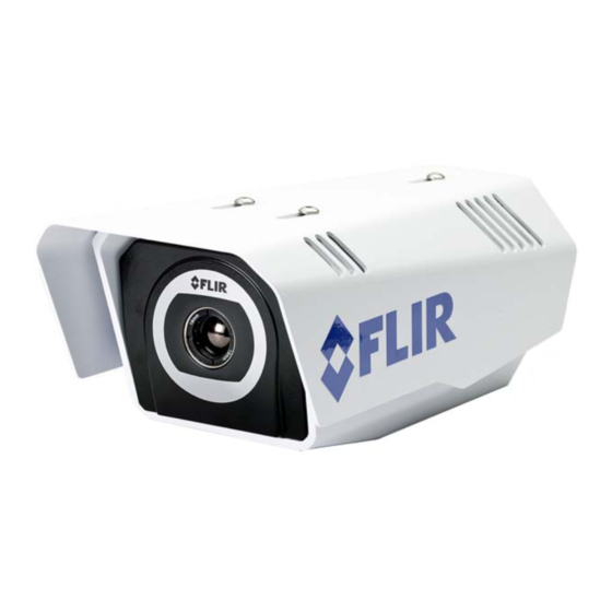
FC-Series S Camera
Quick Connect Guide
Items Included in Kit
2.4 mm slotted
screwdriver
Feb 2013
Advertisement

Summary of Contents for FLIR FC S Series
- Page 1 For installations that are using the Concealed Cable Mounting Arm, refer to the installation manual for instructions: FLIR FC-Series S Installation Manual (427-0073-11-12) Caution! Except as described in this guide, do not disassemble the FC-Series S camera. Damage to the camera can occur as the result of careless handling or electrostatic discharge (ESD).
- Page 2 Step 1 Remove cover: Using 3 mm hex key, loosen four captive screws. Removal of sunshield not necessary. Access captive screws through slots in sunshield. Step 2 Install cables through sealing gland: Gland nut Re-tighten gland nut Video coax after installation is completed.
- Page 3 Step 4 Terminate cables: Connection Purpose 3-pin Jumper Lens heater on/off Analog video test point Analog video 3-pin Terminal AC/DC Power Ethernet PoE power, communications, IP video stream Accessory inputs Reserved for future use Table 1-1: Power Connector Chassis VAC/DC - VAC/DC + Step 5 Connect a ground wire between the ground stud on the...
- Page 4 Typical to good grounding practices, the camera chassis ground should be connected to the lowest resistance path possible. FLIR requires a grounding strap anchored to the grounding lug and connected to the nearest earth-grounding point.


Need help?
Do you have a question about the FC S Series and is the answer not in the manual?
Questions and answers