SCHUNK SWS-001 Installation And Operating Manual
Quick-change system
Hide thumbs
Also See for SWS-001:
- Installation and operating manual (40 pages) ,
- Assembly and operating manual (137 pages)

Subscribe to Our Youtube Channel
Related Manuals for SCHUNK SWS-001


Summary of Contents for SCHUNK SWS-001
- Page 1 Original Manual Quick-Change System SWS-001 Installation and Operating Manual Superior Clamping and Gripping...
- Page 2 Imprint Copyright: This manual remains the copyrighted property of SCHUNK GmbH & Co. KG. It is solely supplied to our customers and operators of our products and forms part of the product. This documentation may not be duplicated or made accessible to third parties, in particu- lar competitive companies, without our prior permission.
-
Page 3: Table Of Contents
7.2 Uncoupling Sequence ..................... 23 7.3 Tool Stand Design ....................24 7.3.1 Tool Locating Features ................26 7.3.2 Tool Stands Sensors ..................26 8 Maintenance ......................27 8.1 Preventive Maintenance ..................27 8.2 Cleaning and Lubrication of the Locking Mechanism ..........29 01.00|SWS-001 |en... - Page 4 8.4 Spring Pin Replacement ..................31 9 Troubleshooting ..................... 33 10 Recommended Spare Parts ..................34 11 Drawings ......................... 35 11.1 Tool Changer ......................35 11.2 E04 Electrical Module ..................... 38 12 Translation of original declaration of incorporation ..........39 01.00|SWS-001 |en...
-
Page 5: About This Manual
Information about avoiding material damage. Applicable documents • General terms of business • Catalog data sheet of the purchased product • Assembly and Operating manuals of the accessories The documents listed here, can be downloaded on our homepage www.schunk.com 01.00|SWS-001 |en... -
Page 6: Basic Safety Notes
• Make sure that the product has a sufficient size for the applica- tion. • Make sure that the environment is free from splash water and vapors as well as from abrasion or processing dust. Exceptions are products that are designed especially for contaminated en- vironments. 01.00|SWS-001 |en... -
Page 7: Product Safety
Provide protective equipment per EC Machinery Directive. 2.4.2 Constructional changes, attachments, or modifications Additional drill holes, threads, or attachments that are not offered as accessories by SCHUNK may be attached only with permission of SCHUNK. Personnel qualification The assembly, initial commissioning, maintenance, and repair of the product may be performed only by trained specialist person- nel. -
Page 8: Notes On Particular Risks
Remove all temporary protective materials (caps, plugs, tape, etc.) on the locking face of Tool Changer and modules prior to operation. Failure to do so will result in damage to Tool Changers, modules, and end-of-arm tooling and could cause injury to personnel. 01.00|SWS-001 |en... - Page 9 The quick-change master SWK locking mechanism must not be actuated without being mounted to the robot interface plate. Damage to the Cover Plate and O-ring may result. • Always attach the quick-change master SWK to the robot in- terface plate prior to attempting any operations. 01.00|SWS-001 |en...
-
Page 10: Warranty
• Intended use in 1-shift operation • Observe the mandatory maintenance and lubrication intervals • Observe the environmental and operating conditions Parts touching the work piece and wear parts are not part of the warranty. 01.00|SWS-001 |en... -
Page 11: Technical Data
Drawings also can found in the product catalog and on our web- site. 2-D and 3-D models are also available on our website. Contact SCHUNK for specific information and drawings regarding your installation. We encourage you to use our service department to review your designs and answer your questions. -
Page 12: Product Overview
Both the SWK and the SWA have two mounting pockets that sup- port optional modules for support of various utility pass-through connections. An electrical module E04 module provides four signal connections, providing the capability of up to eight signal connec- tions to the Tool Changer. 01.00|SWS-001 |en... -
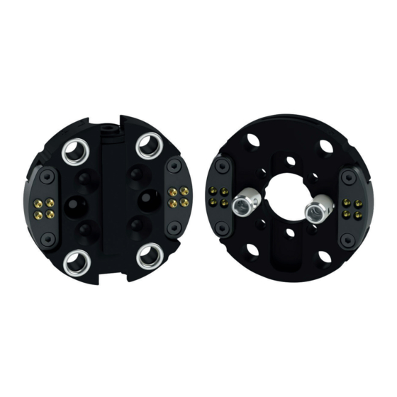
Page 13: Swk Quick-Change Head
The Lock and Unlock air ports are equipped with M3 adjustable el- bow fittings for 4mm diameter tubing. The SWK has two mounting pockets that support optional modules for electrical or other pass- through connections. quick-change head SWK 01.00|SWS-001 |en... -
Page 14: Quick-Change Adapter Swa
Grooves are provided for interfacing with an optional tool stand. A dowel pin on the SWA aligns with a pocket in the master plate to ensure proper coupling orientation. quick-change adapter SWA 01.00|SWS-001 |en... -
Page 15: Assembly
• All pneumatic fittings and tubing must be capable of with- standing the repetitive motions of the application without fail- ing. • The routing of electrical and pneumatic lines must minimize the possibility of stress pullout, kinking, rupture, etc. 01.00|SWS-001 |en... -
Page 16: Swa Quick-Change Adapter Assembly
• Do not use mounting fastener that extend beyond the SWA mating surface. 3 Pneumatic lines and electrical cables are attached, bundled, and must be strain-relieved in a manner that allows for free- dom of movement during operation. For electrical cabling in- ( 6.4, Page structions: 20). 01.00|SWS-001 |en... -
Page 17: Lock/Unlock Pneumatic Connections And Valving
4.5 – 5.5 bar. NOTICE Possible damage to the locking mechanism could occur. • Do not use the Tool Changer in the fail-safe condition for ex- tended periods of time. • Do not transport the Tool Changer in the fail-safe condition. 01.00|SWS-001 |en... -
Page 18: Valve Requirements And Connections
3-way valve as this type of valve is incapable of venting trapped air pressure from within the Tool Changer. Connect the Lock and Unlock supply air to a single 4-way valve with either 4 or 5 port configuration. 01.00|SWS-001 |en... -
Page 19: Manual Uncouple Swk And Swa
3 Using a 1.5mm Ball end Allen wrench, insert it through the Unlock air port and push the locking piston to the unlocked position. 4 Separate the SWA from the SWK, supporting the SWA and tool if attached. 01.00|SWS-001 |en... -
Page 20: Wiring And Electrical Connections For Optional Modules
3 Remove the optional module from the SWK or SWA. Soldering the Electrical Connections 4 Strip the wire the same length as the notch in the pin. 5 Slide a piece of heat shrink tubing over the wire. 6 Solder the wire to the pin. 01.00|SWS-001 |en... - Page 21 8 Repeat this for all the connections. 9 Replace the optional module to the SWK or SWA and secure with the M2 screw using a 1.5mm Allen Wrench. Torque to approximately 0.24 Nm. 01.00|SWS-001 |en...
-
Page 22: Operational Considerations
SWA are aligned axially and are parallel to each other as close- ly as possible. This will minimize tool movement and subse- quent wear during lock-up. Note: Make sure the visual alignment indicators on the SWK and the SWA are aligned properly before coupling to ensure proper orientation. 01.00|SWS-001 |en... -
Page 23: Uncoupling Sequence
3 Move the SWK axially away from the SWA. 4 A sufficient delay must be programmed between unlocking valve actuation and robot motion so that the unlocking process is complete and the SWA is fully released before mov- ing the robot. 01.00|SWS-001 |en... -
Page 24: Tool Stand Design
Lock-up should occur with the SWK in the No-Touch™ locking zone (see the following table), but not touching the SWA. When air is supplied to the lock port, the SWK should draw the SWA into the locked position. 01.00|SWS-001 |en... - Page 25 (Max) (degrees) (Max) (degrees) ±1 ±0.7 ±3 * Maximum values shown. Decreasing actual values will minim- ize wear during coupling/uncoupling. ** Actual allowable values may be higher in some cases, but higher offsets will increase wear during coupling. 01.00|SWS-001 |en...
-
Page 26: Tool Locating Features
“float” be built into the locating system. Other Tool locating feature methods include balls and detents, dowel pins in notched V-grooves, etc. Please consult SCHUNK for recommendations or assistance with locating feature design for your particular tooling. -
Page 27: Maintenance
For a schedule and items that ( 8.1, Page should be visually inspected at regular intervals 27). Spare parts are available from SCHUNK. Please call for recommendations. NOTICE The cleanliness of the work environment strongly influences the trouble-free operation of the changer. - Page 28 • Clear debris from area of the contacts using compressed air. Do not directly clean contacts as abrasion may occur and the per- formance of the contact may be compromised. ( 8.4, Page 31) • Inspect electrical contacts for wear or damage 01.00|SWS-001 |en...
-
Page 29: Cleaning And Lubrication Of The Locking Mechanism
Apply Lubricant to the Alignment Locking Posts on the Tool Plate 4 Apply a moderate coating of lubricant to the alignment locking posts inside and out. 01.00|SWS-001 |en... -
Page 30: Rubber O-Ring Inspection And Replacement
O-ring out of the body. 3 Dip new O-ring in water to aid in installation. 4 Insert the rubber O-ring into the bore. 5 Press the O-ring in by hand until it is seated completely in the bore. 01.00|SWS-001 |en... -
Page 31: Spring Pin Replacement
This may require the replacement of entire pin block assembly. • Gently push spring pin into the block until you feel a click. • Do not use excessive force to push spring pin into pin socket. 01.00|SWS-001 |en... - Page 32 5 Check to see if the spring pin is at the proper height by com- paring it to other original spring pins. If not continue to push the pin into the block until you feel a click or the pin is at the proper height. 01.00|SWS-001 |en...
-
Page 33: Troubleshooting
Unlock (U) port. ( 6.3, Page 17) Air or vacuum trapped in Ensure that the SWK cam is fully a Lock (L) air port. retracted and that there is no air trapped in the Lock (L) air port. 01.00|SWS-001 |en... -
Page 34: Recommended Spare Parts
Recommended Spare Parts Recommended Spare Parts Assembly Part Number Description 0302290 SWK-001-000-000 0302291 SWA-001-000-000 Electrical modules 9960359 Electrical Module, E04-K, 4-Pin, 3Amp/50VAC Master 9960360 Electrical Module, E04-A, 4-Pin, 3Amp/50VAC Tool 01.00|SWS-001 |en... -
Page 35: Drawings
Drawings Drawings 11.1 Tool Changer SWS-001 Tool Changer 01.00|SWS-001 |en... - Page 36 Drawings quick-change head SWK-001 01.00|SWS-001 |en...
- Page 37 Drawings quick change adapter SWA-001 01.00|SWS-001 |en...
-
Page 38: E04 Electrical Module
Drawings 11.2 E04 Electrical Module Electrical Module 01.00|SWS-001 |en... -
Page 39: Translation Of Original Declaration Of Incorporation
Translation of original declaration of incorporation in terms of the Directive 2006/42/EG, Annex II, Part 1.B of the European Parliament and of the Council on machinery. Manufacturer/ SCHUNK GmbH & Co. KG Spann- und Greiftechnik Distributor Bahnhofstr. 106 – 134 D-74348 Lauffen/Neckar... - Page 40 01.00|SWS-001 |en...
Need help?
Do you have a question about the SWS-001 and is the answer not in the manual?
Questions and answers