Advertisement
Quick Links
Pneumatic Division
Richland, Michigan 49083
269-629-5000
!
WARNING
To avoid unpredictable system behavior that can cause personal injury
and property damage:
• Disconnect electrical supply (when necessary) before installation,
servicing, or conversion.
• Disconnect media source and depressurize all media lines
connected to this product before installation, servicing, or
conversion.
• Operate within the manufacturer's specified pressure, temperature,
and other conditions listed in these instructions.
• Medium must be moisture-free if ambient temperature is below
freezing.
• Service according to procedures listed in these instructions.
• Installation, service, and conversion of these products must be
performed by knowledgeable personnel who understand how
pneumatic products are to be applied.
• After installation, servicing, or conversion, media and electrical
supplies (when necessary) should be connected and the product
tested for proper function and leakage. If audible leakage is present,
or the product does not operate properly, do not put into use.
• Warnings and specifications on the product should not be covered
by paint, etc. If masking is not possible, contact your local
representative for replacement labels.
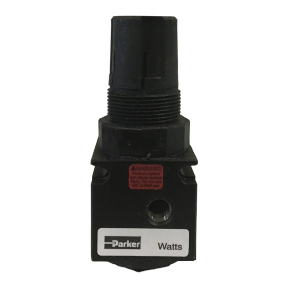
WARNING
!
Product rupture can cause serious injury.
Do not connect regulator to bottled gas.
Do not exceed maximum primary pressure rating.
Safety Guide
For more complete information on recommended application
guidelines, see the Safety Guide section of Pneumatic Division
catalogs or you can download the Pneumatic Division Safety Guide
at: www.wattsfluidair.com
Introduction
Follow these instructions when installing, operating, or servicing
the product.
Application Limits
These products are intended for use in general purpose
compressed media systems only.
Operating Pressure:
Maximum Inlet Pressure
Ambient Temperature Range:
Symbols
➤
Relieving Regulator
Adjustable
Installation
1. The regulator should be installed with reasonable accessibility
for service whenever possible - repair service kits are available.
Keep pipe and tubing lengths to a minimum with inside clean
kPa
PSIG
bar
2068
300
21.0
4.4°C to 48.9°C
➤
Non-Relieving Regulator
Adjustable
Installation and Service Instructions:
IS-R35
R35, 1/8" & 1/4"
Series Regulators
ISSUED: September, 2006
Supersedes: April, 2006
Doc. #ISR35, ECN #060928, Rev. 3
and free of dirt and chips. Pipe joint compound should be
used sparingly and applied only to the male pipe - never into
the female port. Do not use PTFE tape to seal pipe joints -
pieces have a tendency to break off and lodge inside unit,
possibly causing malfunction.
2. Install regulator so that media flow is in the direction of arrow.
Installation must be upstream (high pressure) side and as
close to the devices it is to service (valve, cylinder, tool, etc.).
Mounting may be in any position.
3. Gauge ports are located on both sides of the regulator body
for your convenience. It is necessary to install a gauge or
pipe plugs into each port during installation.
4. For protection against rust, pipe scale, and other foreign
matter, install a filter on the upstream (high pressure) side as
close to the regulator as possible.
Operation
1. Before turning on the media source, disengage the Adjusting
Knob by pulling upward. Turn the Adjusting Knob
counterclockwise until compression is released from the
Control Spring. Then turn on media source and adjust
regulator to desired secondary pressure by turning Adjusting
Knob clockwise. This permits pressure to build up slowly,
preventing any unexpected operation of the valve, cylinders,
tools, etc., attached to the line. Adjustment to desired
secondary pressure can be made only with primary pressure
applied to the regulator.
2. To decrease regulator pressure setting, always reset from a
pressure lower than the final setting desired. For example,
lowering the secondary pressure from 550 to 410 kPa (80 to
60 PSIG) is best accomplished by dropping the secondary
pressure to 350 kPa (50 PSIG), then adjusting upward to 410
kPa (60 PSIG). Push the Adjusting Knob down to lock the
pressure setting.
Reduced Pressure Spring Ranges
"A" Range = 0 – 25 PSI
"B" Range = 0 – 60 PSI
"C" Range = 0 – 125 PSI
!
WARNING
FAILURE OR IMPROPER SELECTION OR IMPROPER USE OF
THE PRODUCTS AND/OR SYSTEMS DESCRIBED HEREIN OR
RELATED ITEMS CAN CAUSE DEATH, PERSONAL INJURY AND
PROPERTY DAMAGE.
This document and other information from The Company, its
subsidiaries and authorized distributors provide product and/or system
options for further investigation by users having technical expertise. It
is important that you analyze all aspects of your application, including
consequences of any failure and review the information concerning
the product or systems in the current product catalog. Due to the
variety of operating conditions and applications for these products or
systems, the user, through its own analysis and testing, is solely
responsible for making the final selection of the products and systems
and assuring that all performance, safety and warning requirements
of the application are met.
The products described herein, including without limitation, product
features, specifications, designs, availability and pricing, are subject to
change by The Company and its subsidiaries at any time without notice.
EXTRA COPIES OF THESE INSTRUCTIONS ARE AVAILABLE FOR
INCLUSION IN EQUIPMENT / MAINTENANCE MANUALS THAT UTILIZE
THESE PRODUCTS. CONTACT YOUR LOCAL REPRESENTATIVE.
Advertisement

Related Manuals for Parker R35 Series


Summary of Contents for Parker R35 Series
- Page 1 Installation and Service Instructions: Pneumatic Division IS-R35 Richland, Michigan 49083 R35, 1/8" & 1/4" Series Regulators 269-629-5000 ISSUED: September, 2006 Supersedes: April, 2006 Doc. #ISR35, ECN #060928, Rev. 3 and free of dirt and chips. Pipe joint compound should be WARNING used sparingly and applied only to the male pipe - never into the female port.
- Page 2 R35, 1/8" & 1/4" Miniature Regulators IS-R35 Service B. Servicing the Poppet Assembly 1. Exhaust system media pressure as previously described. Caution: Disconnect or shut off air supply and exhaust Then remove Bottom Plug by unscrewing it from Body. Next, the primary and secondary pressures before servicing remove Bottom Plug Seal, Poppet Return Spring and Poppet unit.
Need help?
Do you have a question about the R35 Series and is the answer not in the manual?
Questions and answers