Table of Contents
Advertisement
Advertisement
Table of Contents

Subscribe to Our Youtube Channel
Related Manuals for Prodigit 3302F Mainframe


Summary of Contents for Prodigit 3302F Mainframe
- Page 1 3302F Mainframe Operation Manual P/N: 9003302F02 REV:N...
- Page 2 也可能不会含有所有所列的部件。This table shows where these substances may be found in the supply chain of Prodigit electronic information products, as of the date of sale of the enclosed product. Note that some of the component types listed above may or may not be a part of the enclosed product. ○:表示该有毒有害物质在该部件...
- Page 3 Failure to comply with these precautions or with specific warnings elsewhere in this manual violates safety standards of design, manufacture, and intended use of the instrument. PRODIGIT assumes no liability for the customer's failure to comply with these requirements. GENERAL This product is a Safety Class 1 instrument (provided with a protective earth terminal).
- Page 4 DECLARATION OF CONFORMITY Company Name: PRODIGIT ELECTRONICS CO., LTD Address: 8/F,No.88, Baojhong Rd., Sindian District, New Taipei City,Taiwan Declares under sole responsibility that the product as originally delivered Product Names: DC Electronic Loads Model Numbers: 3310F, 3311F, 3312F, 3314F, 3315F, 3330F, 3332F, 3336F, 3340F/G 3341F/G, 3342F/G, 3343G.
- Page 5 SAFETY SYMBOLS Direct current (DC) Alternating current (AC) Both direct and alternating Three-phase alternating current Protective earth (ground) On (Supply) Off (Supply) Fuse Caution!Refer to this manual before using the meter. Caution, risk of electric shock CAT IV – Is for measurements performed at the source of the low-voltage installation. CAT III –...
-
Page 6: Table Of Contents
3302F Mainframe Operation Manual Table of Contents CHAPTER 1 INTRODUCTION ......................1 1.1 F .......................... 2 EATURES 1.2 S ....................2 TANDARD CCESSORIES 1.3 O ..........................2 PTION 1.4 S ......................... 2 PECIFICATIONS CHAPTER 2 INSTALLATION ......................3 2.1 I ........................ - Page 7 Figures FIG 2-1 SET OF SWITCH ........................3 FIG 2-2 FUSE RECEPTACLE......................4 FIG 2-3 3302F REAR PANEL ......................6 FIG 2-4 3302F RS232 CONNECTION ....................6 FIG 2-5 3302F REAR PANEL ......................7 FIG 2-6 3302F USB CONNECTION..................... 7 FIG 2-7 3302F LAN CONNECTION .....................
- Page 8 Tables TABLE 1-1 3310F / 3330F / 3340F/G / 33401F/G SERIES SPECIFICATION LIST ......1 TABLE 1-2 SPECIFICATIONS ......................2 TABLE 4-1 COMMAND TERMINATORS.................... 25 TABLE 4-2 REMOTE CONTROL SETTING COMMAND SUMMARY ..........27 TABLE 4-3 REMOTE CONTROL QUERY COMMAND SUMMARY ........... 28 TABLE 4-4 REMOTE CONTROL LIMIT COMMAND SUMMARY............
-
Page 10: 3302F Mainframe Operation Manual 1
3302F Mainframe Operation Manual 1 Chapter 1 Introduction The 3302F electronic load mainframe is required to provide the DC power conversion and optional computer communications to the ‘F’ series of Load Modules. The 3302F is designed to house any of the following models: Model Max. -
Page 11: Features
1 PC 1.3.7. GPIB cable 1.3.8. GPIB cable 1.3.9. USB TYPE A TO TYPE B cable 1.8 M 1.4 Specifications The specification of 3302F mainframe is shown below in Table 1-2. LINE 100V/115V±10% 200V/230V±10% FREQUENCY 50/60 HZ T1A/250V T0.5A/250V AC INPUT... -
Page 12: Chapter 2 Installation
Prodigit's sales and service office or representative. Your 3302F mainframe was shipped with a power cord for the type of outlet used at your location. If the appropriated cord was not included, please contact your nearest sales office to obtain the correct cord. -
Page 13: Input Fuse
4 PRODIGIT 2.3 Input Fuse This product is fitted with a mains input fuse. If it needs to be replaced please adhere to the Following procedure. BEFORE replacing the fuse you must switch off the unit and mains power outlet and disconnect the plug of the AC Power cable from the input socket of the 3302F If prior to exchanging the fuse, there is any abnormal noise or odour do not use the unit. -
Page 14: Grounding Requirements
3302F Mainframe Operation Manual 5 2.4 Grounding requirements SHOCK HAZARD The unit is grounded via the AC Input. It must be ensured that the correct mains lead with earth pin is used. Correct grounding of your electrical system infrastructure according to national standards must also be observed. -
Page 15: Power Up
2.9 GPIB & RS232 connection option If your 3302F is fitted with GPIB + RS232 interface card then the rear panel will have the necessary interface sockets as shown in Fig 2-3. This connects the 3302F mainframe to RS232 or GPIB port of your computer. -
Page 16: Gpib Connection Option
Panel of 3302F mainframe, The GPIB address of the 3302F mainframe is Set on front panel. Fig 2-5 3302F REAR PANEL 2.12 USB Connection Option Fig 2-6 shows the USB connector in the rear panel of 3302F mainframe. Please refer Appendix B. Fig 2-6 3302F USB Connection 2.13 LAN Connection Option Fig 2-7 shows the LAN connector in the rear panel of 3302F mainframe. -
Page 17: Remote Controller Option
Fig 2-9 shows pin assignments for the DSUB-15 connector when the remote controller option is fitted to the 3302F mainframe. The remote controller allows the first 10 memory locations to be recalled. Set ups saved at these memory locations can include dynamic waveforms and the load ON state. -
Page 18: Analog Programming Input
3302F Mainframe Operation Manual 9 2.16 Analog Programming Input The 3302F mainframe has an analogue programming input. This feature allows an external waveform to be tracked as long as it is within the load’s dynamic capabilities. The analogue programming input is configured as a BNC socket. It will accept a 0-10V signal. This signal is proportional to the load module’s maximum current range. -
Page 19: Chapter 3 Mainframe Operation
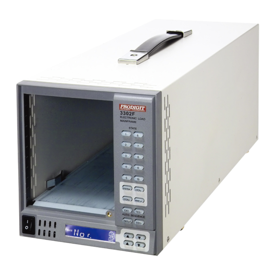
10 PRODIGIT Chapter 3 Mainframe Operation The front panel of 3302F mainframe is shown in Fig 3-1. Fig 3-1 3302F FRONT PANEL... -
Page 20: Fig 3-2 3302F Side Panel
3302F Mainframe Operation Manual 11 Fig 3-2 3302F SIDE PANEL Fig 3-3 3302F REAR PANEL... -
Page 21: Power Switch
12 PRODIGIT 3.1 Power Switch Before switching on the unit please ensure the mains voltage matches the units setting (see Section 2.2 Check Line Voltage) At mains power ON, the following should be apparent. 3.1.1. The mainframe and firmware version is displayed on its screen at the bottom right. - Page 22 3302F Mainframe Operation Manual 13 3.2.2 GPIB Card The LCD will permanently show GPIB if this computer interface has been fitted. 3.2.3 RS232 Card The LCD will permanently show RS232 if this computer interface has been fitted. 3.2.4 USB Card: The LCD will permanently show USB if this computer interface has been fitted.
-
Page 23: Buttons Description
14 PRODIGIT 3.2.7 BANK/T1 Display The upper digits on the right hand side of the screen relate to the memory BANK in normal mode. There are 15 BANKS which can be selected in turn by pressing the upper pair of arrow keys. Each BANK has 10 memory separate memory STATES (locations) which are selected with the lower pair of arrow keys. -
Page 24: Operating Instructions
3302F Mainframe Operation Manual 15 3.3.1 The 4 buttons marked exit, test, enter and edit are used to set an auto-sequence. 3.3.2 The numbered buttons 1~10 are the memory states (locations) for storing or Recalling a load set up. They are also used to select a previously saved Auto-sequence when in test mode 3.3.3 Pressing the system button once allows the GPIB address to be changed by using... - Page 25 3.4.2. STORE/RECALL Operation The function keys on the front panel of 3302F mainframe, 3310F / 3330F / 3340F/G / 33401F/G series electronic load modules 3302F STORE/RECALL Ten electronic load STATE Setting items and 15 BANK a total of 150 electronic load state set, each state can store a variety of electronic load status and settings.
- Page 26 3302F Mainframe Operation Manual 17 3.4.2.1. How to STORE a load set up: 1. Adjust Electronic Load to desired status and settings. 2. With the UP and DOWN keys on the mainframe select the bank (1 to 15) in which you will store the set up 3.
- Page 27 18 PRODIGIT Step 2 Select the memory location (bank and state) that is to be used. Once the Correct location has been selected press the STORE key. This example below Shows bank 01 state 01. After pressing store key the LCD will revert to the Normal message.
- Page 28 3302F Mainframe Operation Manual 19 The “XX” part is the test step (1 to 16 is possible). Once the auto-sequence number has been selected the Memory location of the first test step can be selected. The Arrow keys next to the 3302F LCD are used to select the Memory BANK and memory STATE.
-
Page 29: Fig 3-4 Edit Mode Operation Flow Chart
20 PRODIGIT The REP function allows the auto-sequence to be repeated a number of times. Both sets of arrow keys are used to set The number of repeats between 0 and 9999 times. Once the Number of repeats has been set press the STORE button to Save the auto-sequence. - Page 30 3302F Mainframe Operation Manual 21 3.4.4.2 Test Mode Pressing the TEST button will cause the TEST switch to Illuminate and the LCD to show the last selected Auto-sequence number (F1 to F9). The numbered STATE buttons (1-9) are used to change the Auto-sequence number (F1 ~ F9).
-
Page 31: Fig 3-5 Test Mode Operation Flow-Chart
22 PRODIGIT Example 2: Once the edit mode has been used to set the 16 step auto-sequence the user Can press the TEST key. If the test fails at one of the test steps the LCD will flash “NG” and the test will stop. The user can then press ENTER key to continue the Test or press the EXIT button to leave the test mode. -
Page 32: Chapter 4 Remote Control Programming Operation
There are two sets of programming terms for the 3302F. One is referred to as the SIMPLE format and the other is COMPLEX format. 4.2. RS232 Set-up The RS232 interface of the 3302F mainframe is set up as follows. Baud-rate :9600~115200bps Parity :None... - Page 33 24 PRODIGIT Abbreviation Description Pin1 Carrier Detect Pin2 Receive Pin3 Transmit Pin4 Data Terminal Ready Pin5 Ground Pin6 Data Set Ready Pin7 Request To Send Pin8 Clear To Send Pin9 Ring Indicator PC RS232 Port...
-
Page 34: Programming Syntax, Parenthesis & Terminators
4.3.2. Terminators You have to send the program line terminator character after sending a computer Command, the available command terminator characters that are accepted by the 3302F mainframe is listed in Table 4-1. LF WITH EOI CR,LF CR,LF WITH EOI TABLE 4-1 COMMAND Terminators Semicolon〝;〞The semicolon〝;〞is a back-up command, the semicolon allows you... -
Page 35: Computer Commands: Simple Type Format
4.4. Computer Commands: Simple Type Format The setting and query commands for the 3310F / 3330F / 3340F/G /33401F/G series of load modules when operated within the 3302F mainframe are listed below in table 4-1 and 4-2. MODEL SETTING PRESET NUMERIC... -
Page 36: Table 4-2 Remote Control Setting Command Summary
3302F Mainframe Operation Manual 27 MODEL SETTING PRESET NUMERIC REMARK COMMAND 331XF 333XF 334XF/G 33401F/G VO{SP} {NR2} {;NL} VD{SP} {NR2} {;NL} RD{SP} {NR2} {;NL} IO{SP} {NR2} {;NL} RR{SP} {OFF│NR2} {;NL} 10-1000=10-1000Hz FREQ {NR1} ; {;NL} 0=DC DIM:LEV {NR2}{;│NL} DIM LEVEL,0-10V 0.01-0.99=1-99% DUTY... -
Page 37: Table 4-3 Remote Control Query Command Summary
28 PRODIGIT MODEL QUERY PRESET NUMERIC RETURN COMMAND 331XF 333XF 334XF/G 33401F/G OCP: STEP {?}{;|NL} ###.#### OCP: STOP {?}{;|NL} ###.#### VTH {?}{;|NL} ###.#### OPP: START {?} {;|NL} ###.#### OPP: STEP {?}{;|NL} ###.#### OPP: STOP {?}{;|NL} ###.#### STIME {?}{;|NL} ###.#### OCP {?}{;│NL} ###.####... -
Page 38: Table 4-4 Remote Control Limit Command Summary
3302F Mainframe Operation Manual 29 MODEL LIMIT COMMAND RETURN 331XF 333XF 334XF/G 33401F/G IH IL{SP}{NR2}{;NL} IH IL {?}{;NL} WH WL{SP}{NR2}{;NL} WH WL {?}{;NL} ###.#### VH VL{SP}{NR2}{;NL} VH VL {?}{;NL} ###.#### SVH SVL{SP}{NR2}{;NL} SVH SVL {?}{;NL} ###.#### TABLE 4-4 REMOTE CONTROL LIMIT COMMAND SUMMARY... - Page 39 30 PRODIGIT MODEL STAGE COMMAND REMARK 331XF 333XF 334XF/G 33401F/G LOAD {SP}{ON│OFF│} { ;│NL} LOAD {?} {;│NL} 0:OFF 1:ON MODE {SP} {CC│CR│CV│CP} {;NL} MODE {SP} {CC│CR│CV│} {;NL} MODE {SP} { LED} {;NL} MODE {?} {;│NL} 0:CC 1:CR 2:CV 3:CP 4 : LED NOTE:331XF &...
-
Page 40: Table 4-5 Stage Command Summary
3302F Mainframe Operation Manual 31 MODEL STAGE COMMAND REMARK 331XF 333XF 334XF/G 33401F/G DYN {SP} {ON│OFF│} {;│NL} DYN {?} {;│NL} 0:OFF 1:ON CLR{;│NL} ERR {?}{;│NL} NG {?}{;│NL} 0:GO 1:NG PROT {?}{;│NL} CCR{SP}{AUTO│R2}{;│NL} NGENABLE{SP}{ON│OFF}{; │NL} POLAR{SP}{POS│NEG}{; │NL} START{;│NL} STOP{;│NL} TESTING {?}{;│NL} 0:TEST END,1:TESTING... -
Page 41: Table 4-7 Measure Command Summary
32 PRODIGIT MEASURE COMMAND 331XF 333XF 334XF/G 33401F/G COMMAND RETURN MEAS:CURR {?}{;NL} ###.#### MEAS:VOLT {?}{;NL} ###.#### MEAS:POW {?}{;NL} ###.#### MEAS:VC {?}{;NL} ###.####,###.#### TABLE 4-7 MEASURE COMMAND SUMMARY 331XF 333XF 334XF/G 33401F/G COMMAND RETURN GLOB:PRES{SP}{ONOFF10}{;NL} GLOB:LOAD{SP}{ONOFF10}{;NL} GLOB:MODE{SP}{CCCRCVCP}{;NL} (*9) GLOB:MODE{SP}{CCCRCVCPLED}{; (*9) NL} GLOB:MODE{SP}{CCCRCVLED}{;NL}... - Page 42 3302F Mainframe Operation Manual 33 MPPT CC/CR/CV TEST algorithm:Case in CC MODE, It is divided into two steps,The first step on the basis of an input conditions scanning CCstart => CCstop identify the MPP point,The second steps in accordance with MPP point perturbation (P & O) to find out the true value of MPP,At the end of P&O time, recording an MPP value, and then repeat steps 1 &...
- Page 43 34 PRODIGIT Fig 4-3b MPPT CC/CR/CV command:331XF at r2.08 version above is enabled Command Description Specification MPPT:MODE{SP}{CC|CR|CV}{NL} Select MPPT mode (CC、CR、CV) MPPT:CC:START{SP}{NR2}{NL} Set CC mode starting current of whole same as CC range 2 scan,unit:A MPPT:CC:STOP{SP}{NR2}{NL} Set CC mode end current value at the end same as CC range 2 of whole scan,unit:A...
- Page 44 3302F Mainframe Operation Manual 35 MPPT:CR:Wmax{SP}{NR1}{NL} Set CR mode maximum conductance change same as CR range 1 width at MPPT,unit:Ω ex: 20Ω=50mSiemens MPPT:CV:START{SP}{NR2}{NL} Set CV mode starting voltage of whole same as CV range 2 scan,unit:V MPPT:CV:STOP{SP}{NR2}{NL} Set CV mode end voltage value at the end same as CV range 2 of whole scan,unit:V...
- Page 45 36 PRODIGIT EXAMPLE 2: MPPT CR MODE MPPT:MODE CR MPPT:CR:START 24.0 MPPT:CR:STOP 12.0 MPPT:CR:VH 13.0 MPPT:CR:VL 0.0 MPPT:CR:Wmin 3000 MPPT:CR:Wmax 60 MPPT:SRATE 0.5 MPPT:SCAN:STEP 10 MPPT:SCAN:Tstep 10 MPPT:PO:Tstep 10 MPPT:PO:TIME 10 MPPT:SCOUNT 3 MPPT ON MPP? = 12.411,1.0140,12.584 MPP? = 12.326,1.0110,12.461...
-
Page 46: Table 4-8 Auto Sequence Command List
3302F Mainframe Operation Manual 37 AUTO SEQUENCE: Available for all modules. AUTO SEQUENCE COMMAND NOTE RETURN FILE {SP} {n}{; NL} n=1~9 STEP {SP} {n} {;NL} n=1~16 1~16 TOTSTEP {SP} {n}{;NL} Total step n=1~16 1~16 m=1~10 n=1~15 SB {SP} {m,n} {;NL} m:STATE , n:BANK T1 {SP} {NR2} {;NL}... -
Page 47: Computer Commands: Complex Type Format Complex Type
38 PRODIGIT 4.5. Computer Commands: Complex Type Format COMPLEX TYPE FORMAT MODEL SETTING COMMAND SUMMARY REMARK 331XF 333XF 334XF/G 33401F/G A/us (3310F,11F,12F), [PRESet:] RISE{SP} {NR2} {;NL} mA/us(3314F,15F, 333XF, 334XF/G) A/us (3310F,11F,12F), [PRESet:] FALL{SP}{;NL} mA/us(3314F,15F, 333XF 334XF/G) [PRESet:] PERI PERD:HIGH LOW {SP} {NR2} {;NL}... -
Page 48: Table 4-2B Remote Control Setting Command Summary
3302F Mainframe Operation Manual 39 MODEL SETTING COMMAND SUMMARY REMARK 331XF 333XF 334XF/G 33401F/G [PRESet:] VO{SP} {NR2} {;NL} [PRESet:] VD{SP} {NR2} {;NL} [PRESet:] RD{SP} {NR2} {;NL} [PRESet:] IO{SP} {NR2} {;NL} [PRESet:] RR{SP} {OFF│NR2} {;NL} 10-1000=10-100 [PRESet:]FREQ {NR1} ; {;NL} 0=DC [PRESet:]DIM:LEV {NR2}... - Page 49 40 PRODIGIT MODEL QUERY COMMAND SUMMARY RETURN 331XF 333XF 334XF/G 33401F/G [PRESet:] RISE{?} {;NL} ###.#### [PRESet:] FALL{?}{;NL} ###.#### [PRESet:] PERI PERD:{HIGH LOW}{?} ###.#### {;NL} [PRESet:] LDONv {?}{;NL} ###.#### [PRESet:] LDOFfv {?}{;NL} ###.#### [PRESet:] CCCURR:{HIGH LOW} {?} ###.#### {;NL} [PRESet:] CCCURR{?} {;NL} ###.####...
-
Page 50: Table 4-3B Remote Control Query Command Summary
3302F Mainframe Operation Manual 41 331XF 333XF 334XF/G 33401F/G [PRESet:] DIM: LEV {?}{;|NL} ##.## [PRESet:] DUTY {?}{;|NL} [PRESet:] DIM {?}{;|NL} 0:OFF 1:ON [PRESet:] BW {?} {;│NL} 0:LO 1:HI [PRESet:] AVG {?} {;│NL} [PRESet:] LEDNO {?} {;│NL} TABLE 4-3B REMOTE CONTROL QUERY COMMAND SUMMARY... - Page 51 42 PRODIGIT MODEL STAGE COMMAND REMARK 331XF 333XF 334XF/G 33401F/G [STATe:] LOAD {SP}{ON│OFF} {;│NL} [STATe:] LOAD {?} {;│NL} 0:OFF 1:ON [STATe:] MODE {SP} {CC│CR│CV│CP} {; [STATe:] MODE {SP} {CC│CR│CV│} {; [STATe:] MODE {LED} {;NL} 0:CC 1:CR 2:CV 3:CP 4:LED [STATe:] MODE {?} {;│NL} 331XF &...
-
Page 52: Table 4-5B Stage Command Summary
3302F Mainframe Operation Manual 43 MODEL STAGE COMMAND REMARK 331XF 333XF 334XF/G 33401F/G [STATe:]POLAR{SP}{POS│NEG}{;│NL} [STATe:]START{;│NL} [STATe:]STOP{;│NL} 0:TEST END, [STATe:] TESTING {?}{;│NL} 1:TESTING TABLE 4-5B STAGE COMMAND SUMMARY SYSTEM COMMAND: available for all module COMMAND NOTE RETURN [SYStem:] CHANnel {SP} [A B] {;NL} A B “... -
Page 53: Table 4-8B Auto Sequence Command List
44 PRODIGIT REMARK: Frequency engineering unit: Hz GLOB: GLOBAL ( all channels active in same time ) . Current engineering unit: A Voltage engineering unit: V Resistance engineering unit: Ω Period engineering unit: ms Slew-rate engineering unit: A/us or mA/us... -
Page 54: Remote Control Command Descriptions
3302F Mainframe Operation Manual 45 4.6. Remote Control Command Descriptions 4.6.1. SETTING functions are used to program sink values along with the operating Mode. The user can also preset dynamic waveforms and set up OCP, OPP, OVP & SHORT tests. The special parameters used for the 3340F/G series of LED Simulators are also described in this section. - Page 55 46 PRODIGIT PERI or PERD Command Syntax: [ PRESet:] PERIPERD:HIGHLOW{SP}{ NR2}{;NL} [ PRESet:] PERIPERD:HIGHLOW?{;NL} Purpose: Set and read the combined TLOW and THIGH of a DYNAMIC Waveform Description: The time period combines TLOW (time low) and THIGH (time high) sections of a DYNAMIC waveform.
- Page 56 3302F Mainframe Operation Manual 47 CURR Command Syntax: [ PRESet:] CCCURR{SP}{ NR2}{;NL} [ PRESet:] CCCURR?{;NL} Purpose: Set and read the current. Description: This command is used for setting of load current. 1. The least significant number is the 5 digit after the decimal point.
- Page 57 48 PRODIGIT CRRES Command Syntax: [ PRESet:] CRRES{SP}{ NR2}{;NL} [ PRESet:] CRRES? {;NL} Purpose: Set and read the resistance. Description: This command is used for setting of load resistance. 1. The least significant number is the 5 digit after the decimal point.
- Page 58 3302F Mainframe Operation Manual 49 OCP: STEP Command Syntax: [PRESet:] OCP:STEP {SP}{NR2}{;NL} [PRESet:] OCP:STEP ? {;NL} Purpose: Set and read the increasing value of OCP Test Description: This command is used for setting the increasing value (I-STEP) of OCP Test.
- Page 59 50 PRODIGIT TCONFIG Command Syntax: [PRESet:] TONFIG {NORMAL|OCP|OVP|OPP|SHORT}{;NL} [PRESet:] TONFIG ? {;NL} Purpose: Set and read the function of Dynamic Test Description: There are four options of this command. Those are NORMAL mode, OCP Test, OVP Test, OPP Test and SHORT Mode Test.
- Page 60 3302F Series Mainframe Operation Manual 51 Purpose: Set and read the BW level to LO or HI. Description: The BW command allows the user to changes the bandwidth of the 33401F/G / 3340F/G series load when operating in LED mode. The BW Function can be Used when in CC Mode, CV Mode and CR Mode Range I.
- Page 61 52 PRODIGIT Description: This command is used to set and read the Impedance (Rd) value When the 33401F/G and 3340F/G units are operated in LED mode. The engineering unit is Ω. Command Syntax [PRESet:] IO{SP} {NR2} {;NL} [PRESet:] IO {?}{;|NL} Purpose: Set and read IO current in LED mode.
- Page 62 3302F Series Mainframe Operation Manual 53 Command Syntax [PRESet:] DIM {OFF|ON} [PRESet:] DIM {?}{;|NL} Purpose: This command is set and read dim ON/OFF. Description: This command is required to turn the dimming control function ON/OFF. 0 = off and 1 = ON. DUTY Command Syntax [PRESet:] DUTY {NR1}...
- Page 63 54 PRODIGIT [LIMit:]POWer:{HIGHLOW} or WHWL Command Syntax: [LIMit]:POWer:{ HIGHLOW}{SP}{ NR2 }{;NL} [LIMit]:POWer:{ HIGHLOW} ?{;NL} [WHWL]{SP}{ NR2 }{;NL} [WHWL]?{;NL} Purpose: Set & read the HIGH / LOW load power limits when operating in CP or CR modes. Description: This command is used to set 2 power LIMIT values. Operation Outside these LIMIT values will cause a NG signal.
-
Page 64: Table 4-9 Modules For Each Series
3302F Series Mainframe Operation Manual 55 4.6.3. STATE functions can be used to see the actual operating status of the electronic Load at that time. [STATe:] LOAD {SP}{ONOFF} Command Syntax: [STATe:] LOAD{SP}{ONOFF}{;NL} [STATe:] LOAD ?{;NL} Purpose: Read LOAD ON/OFF status Description: This command is used to see if the Load is ON or OFF 0 = Load OFF 1 = Load ON... - Page 65 56 PRODIGIT [STATe:] PRESet {SP}{ONOFF} Command Syntax: [STATe:] PRESet {SP}{ONOFF}{;NL} [STATe:] PRESet ? {;NL} Purpose: Reads back whether load is in preset mode. Description: This command is used to check if the load is in preset mode. 0 = Preset mode OFF 1 = Preset mode ON [STATe:] SENSe{SP}{ONOFFAUTO}...
-
Page 66: Table 4-10 Error Register
3302F Series Mainframe Operation Manual 57 [STATe:] ERRor Command Syntax: [ STATe:] ERRor ?{;NL} Purpose: Query if there are any errors flagged in the module. Description: 1. ERR? : Read the register of ERR status. TABLE 4-10 shows the Corresponding number of ERR status 2. -
Page 67: Table 4-11 Register Of Protection Status
58 PRODIGIT BIT ID BIT VALUE REMARK bit 0 0 = Off, 1 = Triggered Over Power Protection (OPP) bit 1 0 = Off, 1 = Triggered Over Temperature Protection (OTP) bit 2 0 = Off, 1 = Triggered Over Voltage Protection (OVP) - Page 68 3302F Series Mainframe Operation Manual 59 [SYStem:] RECall{SP}{m}[,n] Command Syntax: [ SYStem:] RECall{SP}{m}[,n] {;NL} Purpose: Recalls the load set-up which has been previously saved in the Memory. Description: This command is for recalling the procedure stored in a specified Memory location where: m = STATE = 1~10 n = BANK = 1~15 If the memory STATE to be used is from the currently selected BANK as shown on...
-
Page 69: Table 4-12 Model Number
60 PRODIGIT MODEL 3310F 3330F 3340F/G 33401F/G 3311F 3332F 3341F/G 3312F 3336F 3342F/G 3314F 3343G 3315F TABLE 4-12 MODEL NUMBER [SYStem:] *RST Command Syntax: [SYStem:] *RST {;NL} Purpose: 330XF Mainframe reset. Description: This command is 330XF Mainframe reset. [SYStem:] REMOTE Command Syntax: [SYStem:] REMOTE {;NL}... - Page 70 3302F Series Mainframe Operation Manual 61 MEAS:VC? Command Syntax: MEAS:VC?{NL} Purpose: Read the voltage and current being taken by the load. Description: Reads the voltage and current meter, Echo format:“###.####,###.####”, The first number is Voltage (V),the second number is Current(A).
-
Page 71: Appendix A Gpib Programming Example
National Instruments Cooperation (NIC) Model PC-2A board provides the interface between the PC-AT and a PRODIGIT MPAL ELECTRONIC LOAD. The appropriate *cib*.obj file is required in each program to properly link the NIC board to C LANGUAGE. and include the <decl.h.>... - Page 72 3302F Series Mainframe Operation Manual 63 ibwrt( load,"pres off;curr:low 0.0;curr:high 1.0;load on ",43); ibwrt( load,"meas:curr ?",10); delay(100); /* Get the load actially sink current from the load */ ibrd( load,rdbuf,20); /* go to local. */ ibloc(load);...
- Page 73 64 PRODIGIT BASICA Example Program LOAD DECL.BAS using BASICA MERGE command. 100 REM You must merge this code with DECL.BAS 105 REM 110 REM Assign a unique identifier to the device "dev5" and store it in variable load%. 125 REM udname$ = "dev5"...
-
Page 74: Appendix B 3302F Usb Instruction
3302F Series Mainframe Operation Manual 65 Appendix B 3302F USB Instruction 1. Install the USB DRIVER, select USB\SETUP\PL-2303 Driver Installer.exe. 2. After the installation, connect the 3302F and PC with USB. Then select the item USB to Serial Port (COM3), set the BAUD-RATE to 115200bps and the Flow control to Hardware. You should then be able to control the 3302F via USB on COM3. - Page 75 66 PRODIGIT...
-
Page 76: Appendix C: 3302F Lan Installation
3302F Series Mainframe Operation Manual 67 Appendix C: 3302F LAN Installation 1. Connect AC power and the network (LAN) cable to the 3302F mainframe. Connect the other side of the network cable to the existing network. 2. After inserting the driver CD-ROM, run LAN\ETM.EXE from the CD. The Ethernet Manager screen will be displayed as shown in Fig C1-1. - Page 77 3302F Mainframe Operation Manual 68 4. The Controller Setup page should be accessible, once everything is set correctly. This allows greater control over the communications interface. 5. Insert the following into the controller set up screen: IP Address: as recommended according to your network...
-
Page 78: Appendix D: Auto-Sequence Quick Start With Example
3302F Series Mainframe Operation Manual Page 69 Appendix D: Auto-Sequence Quick Start with Example An auto-sequence allows the user to step through previously saved set-ups stored in the mainframe’s memory. Up to 9 auto-sequences can be saved. Each auto-sequence can consist of up to 16 steps. - Page 79 3302F Series Mainframe Operation Manual Page 70 Auto-Sequence Example In this example, we will create a program based on following Figure. The program executes steps 1 to 8 in sequence. Auto-sequence Memory Memory Current Execution Time Step number BANK STATE Value (T1+T2) 200mS...
- Page 80 3. Set LOAD ON/OFF Status: Press Load ON 4. Set the current values steps 1~8 and store to memory BANK 3 STATES 1~8 5. Press EDIT key of 3302F mainframe 6. Press the number 2 key to select F2 as the auto sequence location 7.
-
Page 81: Appendix E: Short, Opp And Ocp Test Examples
3302F Series Mainframe Operation Manual Page 72 Appendix E: Short, OPP and OCP test examples The parameters for the Short, Over Power Protection and Over Current Protection tests can be programmed over the optional computer interfaces. The following examples may prove useful. SHORT Test This example sets a short test for 500ms until the STOP command is received.
Need help?
Do you have a question about the 3302F Mainframe and is the answer not in the manual?
Questions and answers