Sign In
Upload
Manuals
Brands
Prodigit Manuals
Control Unit
3341G Series
Prodigit 3341G Series Manuals
Manuals and User Guides for Prodigit 3341G Series. We have
2
Prodigit 3341G Series manuals available for free PDF download: Operation Manual
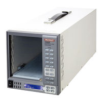
Prodigit 3341G Series Operation Manual (81 pages)
Brand:
Prodigit
| Category:
Industrial Electrical
| Size: 1 MB
Table of Contents
Table of Contents
6
3302F Mainframe Operation Manual 1
10
Chapter 1 Introduction
10
Table 1-1 3310F / 3330F / 3340F/G / 33401F/G Series Specification List
10
Features
11
Standard Accessories
11
Ption
11
Specifications
11
Table 1-2 Specifications
11
Chapter 2 Installation
12
Inspection
12
Check Line Voltage
12
Fig 2-1 Set of Switch
12
Input Fuse
13
Fig 2-2 Fuse Receptacle
13
Grounding Requirements
14
Environmental Requirements
14
Observe the International Electrical Symbol Listed below
14
Cleaning
14
Power up
15
Connection Option
15
Rs232 Interface Option
15
Fig 2-3 3302F Rear Panel
15
Fig 2-4 3302F Rs232 Connection
15
Gpib Connection Option
16
Usb Connection Option
16
Lan Connection Option
16
Fig 2-5 3302F Rear Panel
16
Fig 2-6 3302F Usb Connection
16
Fig 2-7 3302F Lan Connection
16
Remote Controller Option
17
Remote Controller Connection
17
Fig 2-8 3302F Remote Controller Connection
17
Fig 2-9 Model 9933 Remote Controller Connection
17
Analog Programming Input
18
Fig 2-10 Diagram of Analog Programming Input
18
Fig 2-11 Analog Programming Example
18
Chapter 3 Mainframe Operation
19
Fig 3-1 3302F Front Panel
19
Fig 3-2 3302F Side Panel
20
Fig 3-3 3302F Rear Panel
20
Power Switch
21
Lcd
21
Buttons Description
23
Operating Instructions
24
Fig 3-4 Edit Mode Operation Flow Chart
29
Fig 3-5 Test Mode Operation Flow-Chart
31
Chapter 4 Remote Control Programming Operation
32
Introduction
32
RS232 Set-Up
32
Fig 4-1 Rs232 Interface Connection of Rear Panel
32
Programming Syntax, Parenthesis & Terminators
34
Table 4-1 Command Terminators
34
Computer Commands: Simple Type Format
35
Table 4-2 Remote Control Setting Command Summary
36
Table 4-3 Remote Control Query Command Summary
37
Table 4-4 Remote Control Limit Command Summary
38
Table 4-5 Stage Command Summary
40
Table 4-6 System Command Summar
40
Table 4-7 Measure Command Summary
41
Table 4-8 Globe Command Summary
41
Table 4-8 Auto Sequence Command List
46
Computer Commands: Complex Type Format COMPLEX TYPE
47
Format
47
Table 4-2B Remote Control Setting Command Summary
48
Table 4-3B Remote Control Query Command Summary
50
Table 4-4B Remote Control Limit Command Summary
50
Table 4-5B Stage Command Summary
52
Table 4-6B System Command Summary
52
Table 4-7B Measure Command Summary
52
Table 4-8B Auto Sequence Command List
53
Remote Control Command Descriptions
54
Table 4-9 Modules for each Series
64
Table 4-10 Error Register
66
Table 4-11 Register of Protection Status
67
Table 4-12 Model Number
69
Appendix A Gpib Programming Example
71
Appendix B 3302F Usb Instruction
74
Appendix C: 3302F Lan Installation
76
Fig D2-1
76
Appendix D: Auto-Sequence Quick Start with Example
78
Appendix E: Short, Opp and Ocp Test Examples
81
Advertisement
Prodigit 3341G Series Operation Manual (78 pages)
Plug-In Electronic Load module
Brand:
Prodigit
| Category:
Control Unit
| Size: 3 MB
Table of Contents
Table of Contents
5
Chapter 1 Introduction
7
General Description
7
Fig 1-1 3341G 300V/24A/300W Power Contour
7
Fig 1-2 3342G 500V/12A/300W Power Contour
7
Fig 1-3 3343G 500V/24A/300W Power Contour
8
Fig 1-4 Constant Current Mode
8
Fig 1-5 Constant Resistance Mode
8
Fig 1-6 Constant Voltage Mode
9
Fig 1-7 Constant Power Mode
9
Fig 1-8 LED Mode Characteristics
9
Fig 1-9 Dynamic Wave Form
10
Fig 1-10 Rise Time Transition Limitation
11
Features
12
Standard Accessories
12
Ption
13
Specifications
14
Table 1-1 3341G Series Specification
15
Chapter 2 Installation
16
Fig 2-1
16
Binding Post and Withdraw Handle on the Front Panel of 3341G Series Plug-In Load
16
Installation and Removal of 3341G Series Plug in Module
17
Module
17
Environmental Requirements
18
Observe the International Electrical Symbol Listed below
18
Cleaning
18
Power up
18
Fig 2-2 Plug-In Installation and Removal
18
Operating Flow Chart for each Load Module Operation
19
Fig 2-3 3341G Series Electronic Load Module Load Condition Setting Flow Chart
19
Chapter 3 Operation
20
Front Panel Description
20
Fig 3-1 Front Panel of 3341G Plug-In Module
20
Instructions
21
Fig 3-2 Typical Connection of 3341G Series Load Module
46
Fig 3-3 3341G Series Electronic Load DIM
48
Fig 3-4 an Equivalent Circuit in Terms of the Current Monitor
50
Fig 3-5 (Correct) Connections to an Oscilloscope
51
Fig 3-6 (Wrong) Connections to an Oscilloscope
51
Fig 3-7 Analog Programming Load Current in CC Mode Operation
53
Initial Setting of 3341G Series Load Module
54
Table 3-2 3341G Initialize
54
Table 3-3 3342G Initialize
54
Table 3-4 3343G Initialize
55
Input Terminal and Wire Consideration
56
Fig 3-8 Hook Terminal y Type Large Size Terminal Connections
56
Table 3-5 Stranded Copper Wire Ampere Capacity
57
Protection Features
58
Chapter 4 Applications
59
Local Sense Connections
59
Fig 4-1 Local Voltage Sense Connections
59
Remote Sense Connections
60
Fig 4-2 Remote Voltage Sense Connections
60
Constant Current Mode Application
61
Fig 4-3 Constant CURRENT Mode Application
61
Fig 4-4 Dynamic Load Current with Independent Programmed Rise/Fall Slew Rate
62
Constant Voltage Mode Application
63
Fig 4-5 Constant Voltage Mode Application
63
Constant Resistance Mode Application
64
Fig 4-6 Constant Resistance Mode Application
64
Constant Power Mode Application
65
Fig 4-7 CONSTANT POWER MODE APPLICATION
65
Led Mode Applications
66
Fig 4-8 Led's Equivalent Circuit and Characteristic Curve
66
Fig 4-9 LED Driver Ripple
66
Fig 4-10 3 LED Cascading Connection Equivalent Circuit and Characteristic Curve
67
Fig 4-11 Several LED Cascading and Parallel Connection and Characteristic Curve
67
Fig 4-12 LED MODE Operation Mode of the Application
68
The Connection of a Multiple Output Power Supply
69
Fig 4-13 Connection between 3341G Series Plug-In Load and Multiple Output Power
69
Supply
69
Parallel Operation
70
Fig 4-14 3341G Series Plug-In Module Parallel Operation
70
Zero-Volt Loading Application
71
Fig 4-15 Zero-Volt Loading Connection
71
3341G Series Electronic Load Ocp, Opp, Short Operation Flow
72
Chart
72
Fig 4-16 3341G Series Electronic Load OCP, OPP, SHORT Operation Flow Chart
72
Power Supply Ocp Testing
73
Power Supply Opp Testing
75
Led Driver Short Testing
77
Fig 4-17 Short Test Connection
77
Advertisement
Related Products
Prodigit 3343G
Prodigit 3342G
Prodigit 3340F
Prodigit 3341F
Prodigit 3342F
Prodigit 33401F
Prodigit 33401G
Prodigit 33501 Series
Prodigit 33533
Prodigit 33515
Prodigit Categories
Measuring Instruments
Power Supply
Laboratory Equipment
Motherboard
Control Unit
More Prodigit Manuals
Login
Sign In
OR
Sign in with Facebook
Sign in with Google
Upload manual
Upload from disk
Upload from URL