Sign In
Upload
Manuals
Brands
HYDAC FILTER SYSTEMS Manuals
Water Filtration Systems
OF5 N Series
HYDAC FILTER SYSTEMS OF5 N Series Manuals
Manuals and User Guides for HYDAC FILTER SYSTEMS OF5 N Series. We have
1
HYDAC FILTER SYSTEMS OF5 N Series manual available for free PDF download: Installation And Maintenance Instructions Manual
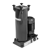
HYDAC FILTER SYSTEMS OF5 N Series Installation And Maintenance Instructions Manual (84 pages)
Offline Filtration
Brand:
HYDAC FILTER SYSTEMS
| Category:
Water Filtration Systems
| Size: 5 MB
Table of Contents
Table of Contents
2
1 General
5
Imprint
5
Documentation Representative
5
Tab. 1 Impressum
5
Tab. 2 Documentation Representative
5
Purpose of this Manual
6
Target Group of the Manual
6
Tab. 3 Target Group
6
Illustrations in the Manual
7
Illustration on the Title Page
7
Fig. 1 Overview / Labeling of the Title Page
7
Representation of Procedural Instructions
8
Representation of Requirements
8
Representation of Intermediate Results/Results
9
Representation of Warning/General Safety Information
10
Signal Words and Their Meaning in the General Safety Information
11
Hazard Symbols / Pictograms
12
Supplementary Symbols
13
Exclusion of Liability/Warranty
14
Notes on Copyright
14
Validity of this Manual
15
2 Safety Information
16
Fire-Fighting / Extinguishing a Fire
17
Fig. 2 Fire Protection Class B
17
Fig. 3 Minimum Distance for Fire Fighting
17
Stoppage in an Emergency (EMERGENCY STOP)
18
Observing Regulatory Information
18
Wear Suitable Clothing
18
3 Overview of the Filtration Unit
19
Proper/Designated Use
20
Improper Use or Use Deviating from Intended Use
21
Checking the Scope of Delivery
22
Tab. 4 Checking the Scope of Delivery
22
Dimensions
23
OF5N - Dimensions
24
Fig. 4 Dimensions OF5N 3433890
24
OF5S - Dimensions
26
Fig. 5 OF5S 3435194 Dimensions
26
Hydraulic Diagram
28
OF5 N - Hydraulic Diagram
28
Fig. 6 Hydraulic Diagram OF5 N
28
OF5 S - Hydraulic Diagram
29
Fig. 7 Hydraulic Circuit OF5 S
29
Technical Data
30
Tab. 5 Technical Data
31
Decoding the Name Plate
32
Fig. 8 Decoding the Type Label
32
Tab. 6 Decoding the Type Label
33
Model Code
34
Fig. 9 Model Code OF5 S/N
34
Requirements of the Workplace & Working Environment
35
Components / Operating Elements
36
Fig. 10 Components/Operating Elements (Example: OF5S)
36
4 Transporting/Storing the Filter Unit
38
Fig. 11 Transporting the OF5 S/N
38
5 Setting up / Assembly / Integration of the Filter Unit
39
Avoiding Siphoning
40
Fig. 12 Avoiding Siphoning
40
Measure or Display Dynamic Pressure / Differential Pressure
41
Fig. 13 Measure or Display Dynamic Pressure / Differential Pressure
41
Avoiding the Mixing of Oils - Emptying the Filter Unit
42
Making the Electrical Connections
43
Electrically Connecting the Electric Motor
43
Fig. 14 Star Delta Connection
44
Connecting the Electric Clogging Indicator (Optional)
45
Connecting the Suction/Pressure Port
45
Fig. 15 Pressure Loss Formula
45
Inserting the Filter Element
47
Commissioning
47
6 Operation
49
OF5N - Operating Mode
50
Fig. 16 OF5N - Transferring and Filtering Operating Mode
50
OF5S - Selecting Operating Modes
51
Fig. 17 OF5S - Selecting the Operating Modes
51
Operating the Change over Valve
52
Operating Mode - Transfer with Filtration a -> T
53
Operating Mode - Transfer Without Filtration a -> B
53
Fig. 18 Operating Modes - Transfer Without Filtration a -> B
53
Fig. 19 Operating Modes - Transfer with Filtration a -> T
53
Operating Mode - Transfer with Filtration T -> B
54
Observing the Optical Clogging Indicator (Optional)
54
Fig. 20 Operating Modes - Transfer with Filtration T -> B
54
Fig. 21 Observe the Optical Clogging Indicator
54
7 Performing Maintenance
55
Maintenance Table
55
Changing the Filter Element
55
8 Rectifying Malfunctions
59
Tab. 7 Error / Cause / Rectification
60
9 Decommissioning / Disposal
61
10 Appendix
62
EC Declaration of Conformity
62
Locating Spare Parts
62
Tab. 8 Spare Parts List OF5
63
Filter Element - Size 330
64
Filter Elements - Size 1300
64
Order Filter Elements
64
Tab. 9 Filter Elements - Size 330
64
Tab. 10 Filter Elements - Size 1300
65
Filter Elements - Size 2600
66
Tab. 11 Filter Elements - Size 2600
66
Clogging Indicators - Technical Data
67
Differential Pressure Indicator, Visual - VM X B.X
67
Fig. 22: Differential Pressure Indicator - Visual VM X B.X
67
Tab. 12: Differential Pressure Indicator -Visual VM X B.X
68
Differential Pressure Indicator, Visual - VM X Bm.X
69
Fig. 23: Differential Pressure Gauge, Visual VM X Bm.X
69
Tab. 13: Differential Pressure Indicator, Visual VM X Bm.X
70
Differential Pressure Gauge, Electric (VM X C.X)
71
Fig. 24 Differential Pressure Indicator, Electrical VM X C.X
71
Tab. 14: Differential Pressure Indicator, Electrical VM X C.X
72
Differential Pressure Gauge, Electric (VM X D.X /-L-XX)
73
Tab. 15 Differential Pressure Indicator, Electrical VM X D.X / -Lxx
74
Finding a Customer Service Team
75
Tab. 16 Customer Service in Germany
75
Table of Illustrations
76
Glossary
79
Index
80
Advertisement
Advertisement
Related Products
HYDAC FILTER SYSTEMS OFU Filtromat
HYDAC FILTER SYSTEMS OF7
HYDAC FILTER SYSTEMS OF5 S Series
HYDAC FILTER SYSTEMS OLFCM 60
HYDAC FILTER SYSTEMS OLFP-3 Series
HYDAC FILTER SYSTEMS OLFP-3/Z-ZZ-Z-TM-NZ
HYDAC FILTER SYSTEMS OLFPCM-6/3-GN-MA-TM-NZ
HYDAC FILTER SYSTEMS OLFP-6/z-zz-z-DM-NE
HYDAC FILTER SYSTEMS OLFCM 5/15
HYDAC FILTER SYSTEMS OLF-10/4 Series
HYDAC FILTER SYSTEMS Categories
Water Filtration Systems
Control Unit
Industrial Equipment
Measuring Instruments
Test Equipment
More HYDAC FILTER SYSTEMS Manuals
Login
Sign In
OR
Sign in with Facebook
Sign in with Google
Upload manual
Upload from disk
Upload from URL