HYDAC FILTER SYSTEMS MFU-10P9S Series Operating And Maintenance Instructions Manual
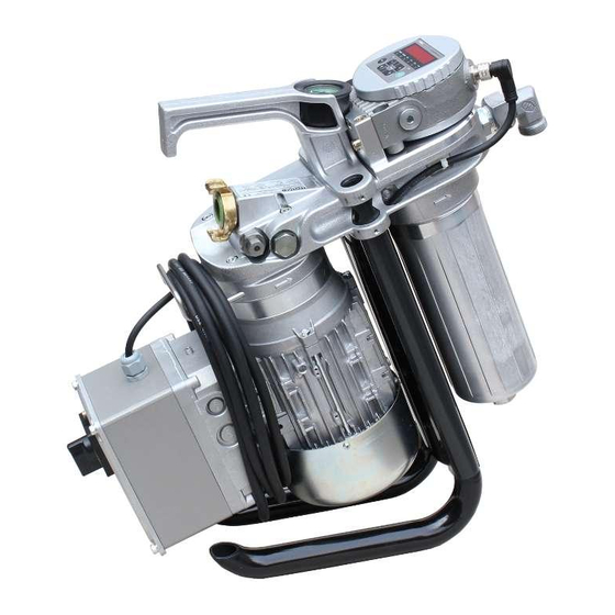
Mobilefiltration unit
Hide thumbs
Also See for MFU-10P9S Series:
- Operating and maintenance instructions manual (100 pages)
Chapters
Table of Contents

Related Manuals for HYDAC FILTER SYSTEMS MFU-10P9S Series


Summary of Contents for HYDAC FILTER SYSTEMS MFU-10P9S Series
- Page 1 MFU-10P9S-... MobileFiltration Unit Operating and Maintenance Instructions English • (translation of original instructions) Document No. : 4391553b Follow these instructions for proper and safe use. Keep for future reference.
- Page 2 The contact data of the person authorized with the documentation is: Günter Harge c/o HYDAC International GmbH, Industriegebiet, 66280 Sulzbach / Saar Germany Telephone: +49 6897 509 1511 Telefax: +49 6897 509 1394 E-mail: guenter.harge@hydac.com Date of printing: 7/6/2020 © HYDAC FILTER SYSTEMS GmbH 2020 Subject to technical modifications.
-
Page 3: Table Of Contents
HYDAC FILTER SYSTEMS GMBH Table of Contents Table of Contents 1 General ........................ 6 Target group of the manual ................ 6 Illustrations in the manual................ 7 1.2.1 Illustration on the title page .............. 7 1.2.2 Representation of requirements............ 8 1.2.3 Representation of procedural instructions ......... 8 1.2.4... - Page 4 Table of Contents HYDAC FILTER SYSTEMS GMBH 3.7.1.1 MFU-10P9 - Dimensions / hydraulic diagram ...... 36 Design and function.................. 39 4 Design and function .................... 41 5 Transportation / Storage (< 6 months) .............. 43 Storing the filter unit (>6 months) .............. 44 Storing the filter unit with hoses and lances .......... 45 6 Setting up / assembly / integration of the filter unit ..........
- Page 5 HYDAC FILTER SYSTEMS GMBH Table of Contents Maintenance table .................. 81 Changing the filter element ................ 82 Removing/installing the quick coupling ............ 88 Removing/installing the protective screen ............ 90 9.4.1 Removing/mounting the push-in protective screen...... 91 9.4.2 Removing/installing the push-in protective screen...... 93 Checking/cleaning the protective screen............ 95 Protective screen for changing the ContaminationSensor ...... 97...
-
Page 6: General
1 | General HYDAC FILTER SYSTEMS GMBH 1 General Before you use this product for the first time, read this manual at least up to the chapter "Operation". If you would like to carry out maintenance or troubleshooting, you can find the proce- dure in the respective chapters. -
Page 7: Illustrations In The Manual
HYDAC FILTER SYSTEMS GMBH General | 1 1.2 Illustrations in the manual You will find illustrations in this manual. You can find details re- garding these in the following chapters. 1.2.1 Illustration on the title page You will find the following information on the title page of this... -
Page 8: Representation Of Requirements
1 | General HYDAC FILTER SYSTEMS GMBH Please note that you can directly access information through the directories. However, this does not release you from the obligation to read this manual fully before commissioning. The document no. with the index (4) is meant for identifying and reordering the manual. -
Page 9: Representation Of Intermediate Results/Results
HYDAC FILTER SYSTEMS GMBH General | 1 Procedural instructions with a random sequence Procedural instructions that have a random sequence are listed as bullet points (-). An example of a procedural instruction with a random se- quence: – Clean the display. -
Page 10: Representation Of Warning/General Safety Information
1 | General HYDAC FILTER SYSTEMS GMBH 1.2.5 Representation of warning/general safety information All the warning / general safety information in this manual are highlighted with pictograms and signal words. The pictogram and the signal word give you an indication of the severity of the danger. -
Page 11: Signal Words And Their Meaning In The General Safety Information
HYDAC FILTER SYSTEMS GMBH General | 1 1.2.6 Signal words and their meaning in the general safety information In these instructions you will find the following signal words: DANGER DANGER – The signal word indicates a hazardous situation with a high level of risk, which, if not avoided, will result lethal or serious injury. -
Page 12: Supplementary Symbols
1 | General HYDAC FILTER SYSTEMS GMBH 1.3 Supplementary symbols You will find the following symbols in the manual as additional details: Tip for handling the product Required tools 1.4 Exclusion of liability/warranty For the warranty provided by us, please refer to the Terms of Delivery. -
Page 13: Notes On Copyright
HYDAC FILTER SYSTEMS GMBH General | 1 1.5 Notes on copyright All copyrights for this manual lies with the manufacturer. No part of this manual may be reproduced in any form or pro- cessed, duplicated or distributed using electronic systems with- out the written consent of the manufacturer. -
Page 14: Safety
2 | Safety HYDAC FILTER SYSTEMS GMBH 2 Safety The product is designed as safe. In spite of that, there is dan- ger in some actions that can only be avoided by using the right procedures. These correct procedures and points, which must be followed, are described in this manual. - Page 15 HYDAC FILTER SYSTEMS GMBH Safety | 2 – To train the personnel at regular intervals and to inform them of the hazards – To provide the necessary protective equipment to the per- sonnel Staff who work with the product must be aware of the dangers...
-
Page 16: Tab. 2 Target Group / Required Personnel Qualification
2 | Safety HYDAC FILTER SYSTEMS GMBH Activity Personnel Knowledge Disposal Specialist personnel Knowledge of envi- - General ronmentally friendly disposal of materi- als and matter is re- quired. Knowledge of de- contamination of contaminants is re- quired. Knowledge of recy- cling is required. -
Page 17: Hazard Symbols / Pictograms
HYDAC FILTER SYSTEMS GMBH Safety | 2 2.2 Hazard symbols / pictograms The following are the safety symbols / pictograms in this man- ual. They indicate specific dangers to persons, property or to the environment. Observe these safety symbols / pictograms and act with particular caution in such cases. - Page 18 2 | Safety HYDAC FILTER SYSTEMS GMBH Wear eye protection. Use protective gloves. Others symbols used These marks can be found for all safety and warning instruc- tions in this manual which indicate a particular danger to per- sons, property or the environment.
-
Page 19: Danger Notifications
HYDAC FILTER SYSTEMS GMBH Safety | 2 able to assess and perform the work assigned to them, they are also able to recognize potential dangers. Specialist personnel - Mechanic Such persons have specific specialist training and several years' work experience. They are... - Page 20 2 | Safety HYDAC FILTER SYSTEMS GMBH Life phase - Commissioning / Operation The following risks could arise during the Commissioning / Op- eration life phase: NOTICE Impermissible operating conditions or operating media The filter unit will be damaged. u Ensure use of permissible operating media.
- Page 21 HYDAC FILTER SYSTEMS GMBH Safety | 2 NOTICE Missing filter element/empty element Leakages in the filter housing u Never operate the filter unit without a filter element or an empty element inserted. NOTICE Faulty assembly of the quick coupling Leaks and/or air entry at the quick coupling u Seal the quick coupling correctly.
-
Page 22: Safety Marking
2 | Safety HYDAC FILTER SYSTEMS GMBH 2.4 Safety marking The following safety markings, labels / signs are provided on the product. The labels / signs on the product must always be easy to read. Fig. 2: Safety marking, label / sign on the product... -
Page 23: Observing Regulatory Information
HYDAC FILTER SYSTEMS GMBH Safety | 2 2.5 Observing regulatory information Observe the following regulatory information and directives: – Legal and local regulations for accident prevention – Legal and local regulations for environmental protection and environmental requirements – Country-specific regulations, organization-specific regula- tions –... -
Page 24: Fig. 4 Minimum Distance For Fire Fighting
2 | Safety HYDAC FILTER SYSTEMS GMBH Fig. 4: Minimum distance for fire fighting 24 / 124 BeWa MFU-10P 4391553b en-us... - Page 25 HYDAC FILTER SYSTEMS GMBH Performance and product description | 3 3 Performance and product description The MobileFiltration Unit MFU is used as a portable filter unit for filling or emptying hydraulic systems, flushing small hy- draulic systems as well as for cleaning in bypass flow. Solid particle contamination as well as free water can be removed by the filter elements.
-
Page 26: Performance And Product Description
3 | Performance and product description HYDAC FILTER SYSTEMS GMBH The version of the cleanliness classes can be selected in accor- dance with ISO, SAE or NAS. The supply voltage of the Con- taminationSensor is available after switching on the filter unit. -
Page 27: Proper/Designated Use
HYDAC FILTER SYSTEMS GMBH Performance and product description | 3 3.2 Proper/Designated Use The MFU filter unit is used as a portable filter unit for filling or emptying hydraulic systems, flushing or filtering hydraulic sys- tems in the bypass flow, and recirculation with / without simul- taneous filtration. -
Page 28: Improper Use Or Use Deviating From Intended Use
3.3 Improper use or use deviating from intended use Any other or extending use beyond this shall not be considered intended use. HYDAC FILTER SYSTEMS GMBH will assume no liability for any damage resulting from such use. This risk is borne solely by the owner. -
Page 29: Checking The Scope Of Delivery
HYDAC FILTER SYSTEMS GMBH Performance and product description | 3 3.4 Checking the scope of delivery In this chapter, you will find the scope of delivery for the deliver of the MFU. With this, you can check the completeness of the scope of the delivery. -
Page 30: Decoding The Name Plate
3 | Performance and product description HYDAC FILTER SYSTEMS GMBH 3.5 Decoding the name plate Identification details of the filter unit can be found on the name plates on the filter unit and the components. Always mention the part no. and the serial no. when contacting HYDAC. - Page 31 HYDAC FILTER SYSTEMS GMBH Performance and product description | 3 Flow rate Flow rate Weight Empty weight BeWa MFU-10P 4391553b en-us 31 / 124...
-
Page 32: Model Code
3 | Performance and product description HYDAC FILTER SYSTEMS GMBH 3.5.1 Model Code The filter unit is defined by the following model code: MFU - 15 E 9 - S M - F E / - Series MFU = Mobile Filter Unit... -
Page 33: Technical Data
HYDAC FILTER SYSTEMS GMBH Performance and product description | 3 3.6 Technical data If you are aware of the technical data of the filter unit, you will be able to use it optimally. The technical data of the filter unit... -
Page 34: Tab. 4 Technical Data
3 | Performance and product description HYDAC FILTER SYSTEMS GMBH MFU-10P Permitted air humidity dur- ≤ 80% relative humidity, non- ing storage condensing Permitted air during storage Clean, salt-free air, not near oxi- dizing substances (rust film) Storage duration: Indefinite. Before the unit is started up... -
Page 35: Dimensions And Hydraulic Shematic
HYDAC FILTER SYSTEMS GMBH Performance and product description | 3 3.7 Dimensions and Hydraulic shematic The dimensions and hydraulic diagrams of the various product variants can be found below. Check the model code on the name plate of the filter unit. -
Page 36: Mfu-10P9 - Dimensions / Hydraulic Diagram
3 | Performance and product description HYDAC FILTER SYSTEMS GMBH 3.7.1.1 MFU-10P9 - Dimensions / hydraulic diagram The filter unit with AC electric motor has the following dimen- sions: Fig. 8: 4216883 - EBZ MFU-10P9-Sx-FE - AC All dimensions in mm. -
Page 37: Fig. 9 4216883 - Ebz Mfu-10P9-Sx-Fe - Dc
HYDAC FILTER SYSTEMS GMBH Performance and product description | 3 The filter unit with DC electric motor has the following dimen- sions: Fig. 9: 4216883 - EBZ MFU-10P9-Sx-FE - DC All dimensions in mm. BeWa MFU-10P 4391553b en-us 37 / 124... -
Page 38: Fig. 10 Hydraulic Diagram Mfu-10P
3 | Performance and product description HYDAC FILTER SYSTEMS GMBH Hydraulic circuit: Fig. 10: Hydraulic diagram MFU-10P 38 / 124 BeWa MFU-10P 4391553b en-us... -
Page 39: Design And Function
HYDAC FILTER SYSTEMS GMBH Performance and product description | 3 3.8 Design and function The following components/operating elements can be found on the filter unit: Fig. 11: Components MFU-10 P IN Inlet OUT Outlet BeWa MFU-10P 4391553b en-us 39 / 124... - Page 40 3 | Performance and product description HYDAC FILTER SYSTEMS GMBH 30 Name plate of the filter unit 110 Connector head 111 Transport handle 115 Vane pump 132 Cable holder 133 Clogging indicator / back-pressure indicator 140 Pressure relief valve 180 Pressure relief valve for the ContaminationSensor...
-
Page 41: Design And Function
HYDAC FILTER SYSTEMS GMBH Design and function | 4 4 Design and function The following components/operating elements can be found on the filter unit: Fig. 12: Components MFU-10 P IN Inlet OUT Outlet BeWa MFU-10P 4391553b en-us 41 / 124... - Page 42 4 | Design and function HYDAC FILTER SYSTEMS GMBH 30 Name plate of the filter unit 110 Connector head 111 Transport handle 115 Vane pump 132 Cable holder 133 Clogging indicator / back-pressure indicator 140 Pressure relief valve 180 Pressure relief valve for the ContaminationSensor...
-
Page 43: Transportation / Storage (< 6 Months)
HYDAC FILTER SYSTEMS GMBH Transportation / Storage (< 6 months) | 5 5 Transportation / Storage (< 6 months) You will find the respective information on the prevention of damage to the filter unit during transportation or storage (<6 months) in this chapter. For storing the filter unit >6 months, see Storing the filter unit (>6 months) [} 44]. -
Page 44: Storing The Filter Unit (>6 Months)
5 | Transportation / Storage (< 6 months) HYDAC FILTER SYSTEMS GMBH 5.1 Storing the filter unit (>6 months) You will find the respective information on the prevention of damage to the filter unit during transportation or storage (>6 months) in this chapter. -
Page 45: Storing The Filter Unit With Hoses And Lances
HYDAC FILTER SYSTEMS GMBH Transportation / Storage (< 6 months) | 5 5.2 Storing the filter unit with hoses and lances If the filter unit is equipped with the hoses including lances from the accessories, here, you will find tips and options to place the lances during transport and storage. -
Page 46: Fig. 15 Mfu Storage - Option
5 | Transportation / Storage (< 6 months) HYDAC FILTER SYSTEMS GMBH Insert both the lances into one another in the holder on the fil- ter unit. The type of storage given in Option 2 is only possible when the feet are parallel to each other. -
Page 47: Setting Up / Assembly / Integration Of The Filter Unit
HYDAC FILTER SYSTEMS GMBH Setting up / assembly / integration of the filter unit | 6 6 Setting up / assembly / integration of the filter unit Observe the following notices for setting up the unit. NOTICE There is a risk of the unit tipping or slipping away due to vibra- tions The filter unit will be damaged. - Page 48 6 | Setting up / assembly / integration of the filter unit HYDAC FILTER SYSTEMS GMBH Fig. 16: Increasing the stability/adjusting the feet If the feet are not locked in the intended positions of 0° or 44°, the filter unit can tip. Only use the intended positions of 0° or 44°...
-
Page 49: Fig. 17: Adjusting The Feet 0°⇨ 44
HYDAC FILTER SYSTEMS GMBH Setting up / assembly / integration of the filter unit | 6 Fig. 17: Adjusting the feet 0°⇨ 44° To adjust the two feet from 0° to 44°, proceed as follows: 1. Fully unscrew both screws counterclockwise with an Allen key. -
Page 50: Fig. 18: Adjusting The Feet 44°⇨ 0
6 | Setting up / assembly / integration of the filter unit HYDAC FILTER SYSTEMS GMBH Fig. 18: Adjusting the feet 44°⇨ 0° To adjust the two feet from 44° to 0°, proceed as follows: 4. Fully unscrew both screws counterclockwise with an Allen key. -
Page 51: Avoiding Siphoning
HYDAC FILTER SYSTEMS GMBH Setting up / assembly / integration of the filter unit | 6 6.2 Avoiding siphoning If there is a height difference ΔH between the suction side and pressure side container side / system, the low lying line can develop a suction effect and trigger the siphoning effect be- tween the communicating containers / systems. - Page 52 6 | Setting up / assembly / integration of the filter unit HYDAC FILTER SYSTEMS GMBH After the filter unit is switched off, the height difference/pri- mary pressure can cause flow to occur both in the feed direc- tion and against the feed direction and the fluid can leak un- controllably.
-
Page 53: Avoiding The Mixing Of Oils - Emptying The Filter Unit
HYDAC FILTER SYSTEMS GMBH Setting up / assembly / integration of the filter unit | 6 6.3 Avoiding the mixing of oils - Emptying the filter unit If you want to use the same oil for operation as in the previous operation, it is not serious if the oils are mixed. -
Page 54: Making The Electrical Connections
6 | Setting up / assembly / integration of the filter unit HYDAC FILTER SYSTEMS GMBH 6.4 Making the electrical connections Depending on the version, the filter unit has different electric motors (e.g. different voltage/performance/number of phases, with/without power plug etc.). -
Page 55: Filter Unit Without Power Plug/Without Connection Cable
HYDAC FILTER SYSTEMS GMBH Setting up / assembly / integration of the filter unit | 6 6.4.1 Filter unit without power plug/without connection cable Depending on the version, the filter unit has neither a power plug nor a connection cable. Connect up the filter unit with a suitable connection cable and/or power plug. - Page 56 6 | Setting up / assembly / integration of the filter unit HYDAC FILTER SYSTEMS GMBH 5. Switch the filter unit on at the main switch. ð The motor pump assembly begins to turn. 6. Switch the filter unit off at the main switch.
- Page 57 HYDAC FILTER SYSTEMS GMBH Setting up / assembly / integration of the filter unit | 6 6.4.3 Connecting filter units with a power plug for 400 V AC, 3 phases The 400 V AC, 3 phase version of the filter unit is equipped with a main switch, motor protection and connection plug.
-
Page 58: Connecting The Suction/Pressure Port
6 | Setting up / assembly / integration of the filter unit HYDAC FILTER SYSTEMS GMBH 6.5 Connecting the suction/pressure port Install the filter unit securely in a system/an assembly, take the pressure loss into account with the piping or hose system. You will find the respective formula to calculate the pressure loss. - Page 59 HYDAC FILTER SYSTEMS GMBH Setting up / assembly / integration of the filter unit | 6 – Note that the nominal size of the connected hose/piping must correspond to the cross-section of the connection thread. – Make sure that the connection hoses/piping (suction side/ pressure side) do not cause any tension or vibrations to be carried over to the filter unit.
-
Page 60: Attaching/Connecting The Suction/Pressure Hoses (Accessories)
6 | Setting up / assembly / integration of the filter unit HYDAC FILTER SYSTEMS GMBH 6.6 Attaching/connecting the suction/pressure hoses (accessories) The suction/pressure hoses from the filter unit Accessories list [} 108] are matched to the filter unit. If you use different con- nection hoses, take into account the pressure loss when con- necting suction/pressure hoses. -
Page 61: Commissioning The Filter Unit
HYDAC FILTER SYSTEMS GMBH Setting up / assembly / integration of the filter unit | 6 6.7 Commissioning the filter unit When you have checked the points listed here and can answer them with OK, the filter unit is ready for operation. - Page 62 6 | Setting up / assembly / integration of the filter unit HYDAC FILTER SYSTEMS GMBH 11. Switch the filter unit on and monitor the suction action via the transparent suction hose. If the filter unit does not pump any fluid after a max. of 5 minutes of opera- tion, switch the filter unit off.
- Page 63 HYDAC FILTER SYSTEMS GMBH Manual operation | 7 7 Manual operation Select the required operating mode as described in Chapter Selecting the operating modes [} 65]. Connect the suction port/pressure port to the containers to be cleaned and switch the filter unit on at the main switch.
-
Page 64: Manual Operation
7 | Manual operation HYDAC FILTER SYSTEMS GMBH 7.1 Switching the filter unit on or off/EMERGENCY- STOP 1. Switch the filter unit on at the main switch to operate it. ð The filter unit starts pumping. 2. Switch the filter unit off at the main switch. -
Page 65: Selecting The Operating Modes
HYDAC FILTER SYSTEMS GMBH Manual operation | 7 7.3 Selecting the operating modes Select the optimal operating mode for your requirement. In or- der to do this, use a suitable filter element (900) or an empty element (910). Details for insertion or exchanging this can be found in Chapter Changing the filter element [} 82]. -
Page 66: Recirculation With Filtration/Dewatering
7 | Manual operation HYDAC FILTER SYSTEMS GMBH 7.3.1 Recirculation with filtration/dewatering For the operating mode recirculation with filtration orrecircula- tion with filtration/dewatering use the respective filter element (900) with the required filtration rating. An overview of the available filter elements with their filtration rating (900) can be found in Chapter Finding spare parts/accessories [} 103]. - Page 67 HYDAC FILTER SYSTEMS GMBH Manual operation | 7 5. During recirculation, continuously monitor the filling level on the oil tank/container to be filled. If the required filling quantity is reached, switch the filter unit off at the main switch. 6. Release the pressure hose at the quick coupling, see Removing/installing the quick coupling [} 88].
-
Page 68: Circulation Pumping Without Filtration
7 | Manual operation HYDAC FILTER SYSTEMS GMBH 7.3.2 Circulation pumping without filtration In operating mode Recirculation without filtration, replace the filter element (900) with an empty element (910). A suitable empty element (910) can be found in Chapter Find- ing spare parts/accessories [} 103]... -
Page 69: Release The Pressure Hose At The Quick Coupling, See Removing/Installing The Quick Coupling [} 88]
HYDAC FILTER SYSTEMS GMBH Manual operation | 7 6. If the required filling quantity is reached, switch the filter unit off at the main switch. 7. Release the pressure hose at the quick coupling, see Removing/installing the quick coupling [} 88]. -
Page 70: Cleaning Up To The Required Cleanliness Class
7 | Manual operation HYDAC FILTER SYSTEMS GMBH 7.3.3 Cleaning up to the required cleanliness class In order to clean oil in an oil tank/container to the required cleanliness class. proceed as follows. Fig. 27: Example of application: Cleaning up to the required cleanli-... -
Page 71: Empty The Contents Of The Pressure Hose Into The Oil Tank/Container
HYDAC FILTER SYSTEMS GMBH Manual operation | 7 2. Connect the pressure hose to the oil tank/container and fit the pressure hose in it and also secure it against fall- ing out. 3. Connect the filter unit to the voltage source. -
Page 72: Operation With Accessories
7 | Manual operation HYDAC FILTER SYSTEMS GMBH 7.4 Operation with accessories In order to adapt the filter unit to your requirements, you can select some items from the accessories list. While using ac- cessories, the technical framework conditions can change in some cases such as the maximum permissible viscosity short time duty instead of continuous operation, etc. -
Page 73: Using A Flow Rate Meter
HYDAC FILTER SYSTEMS GMBH Manual operation | 7 7.4.2 Using a flow rate meter Containers and plants can be precisely filled with the flow rate meter. After a reset (RESET), the large digital display shows you the currently filled volume. -
Page 74: Using A Suction Line Filter On The Suction Hose
7 | Manual operation HYDAC FILTER SYSTEMS GMBH 7.4.4 Using a suction line filter on the suction hose With a suction line filter on the suction hose, even very dirty fluids can be suctioned. They protect the pump while doing so and the internally installed strainer against blocking up quickly due to too much dirt. -
Page 75: Rectifying Malfunctions
HYDAC FILTER SYSTEMS GMBH Rectifying malfunctions | 8 8 Rectifying malfunctions In order to get quick and immediate assistance in the case of errors, you will find the most often occurring errors with their cause and remedy with suitable specialist personnel. - Page 76 8 | Rectifying malfunctions HYDAC FILTER SYSTEMS GMBH Malfunction Cause(s) Rectification There is air in Fill the vane the suction line pump through and the vane the suction pump. hose / quick cou- pling. The viscosity of Check the vis-...
-
Page 77: Tab. 5 Error/Cause/Rectification
HYDAC FILTER SYSTEMS GMBH Rectifying malfunctions | 8 Malfunction Cause(s) Rectification The viscosity of Check the vis- the fluid is too cosity of the high. fluid. Heat the fluid to achieve the per- missible viscos- ity. Leaks in the Wrong, missing,... - Page 78 8 | Rectifying malfunctions HYDAC FILTER SYSTEMS GMBH Malfunction Cause(s) Rectification The vane pump Push the suction ContaminationSensor draws in air. The hose deeper into displays high suction hose is the tank, be- values. positioned above neath the oil the oil level.
- Page 79 HYDAC FILTER SYSTEMS GMBH Rectifying malfunctions | 8 Malfunction Cause(s) Rectification blocked. Re- move the ContaminationSensor , blow it out with compressed air in the direction opposite to the flow direction. Check the vane ContaminationSensor pump for proper does not recog- functioning.
-
Page 80: Performing Maintenance
9 | Performing Maintenance HYDAC FILTER SYSTEMS GMBH 9 Performing Maintenance For a long, trouble-free service life of the filter unit, regular maintenance activities are required. In this chapter, you will find the description of the required maintenance activities and the qualifications of the staff needed to carry out these tasks. -
Page 81: Maintenance Table
HYDAC FILTER SYSTEMS GMBH Performing Maintenance | 9 9.1 Maintenance table Additional infor- mation Observe the opti- cal clogging indi- cator Checking/clean- ing the protective screen Removing/in- stalling the pro- tective screen 9.4.1 Removing/mount- ing the push-in protective screen 9.4.2 Removing/in-... -
Page 82: Changing The Filter Element
9 | Performing Maintenance HYDAC FILTER SYSTEMS GMBH Additional infor- mation Changing the fil- ter element Checking/clean- ing the protective screen 1 - Operating personnel; 2 - Specialist personnel – Mechanical 9.2 Changing the filter element In this chapter, you will find the procedure for changing the fil- ter element. - Page 83 HYDAC FILTER SYSTEMS GMBH Performing Maintenance | 9 NOTICE Missing filter element/empty element Leakages in the filter housing u Never operate the filter unit without a filter element or an empty element inserted. The filter element/empty element has two seal rings (901)+(902) installed.
- Page 84 9 | Performing Maintenance HYDAC FILTER SYSTEMS GMBH 2. Now allow the filter unit to continue running until there is no more fluid flowing out of the pressure hose. 3. Remove the pressure hose from the container. 4. Switch off the filter unit at the main switch and unplug the power connector.
- Page 85 HYDAC FILTER SYSTEMS GMBH Performing Maintenance | 9 7. Remove the used filter element. 8. Dispose of the used filter element and the residual oil volume in an environmentally friendly manner in accor- dance with the applicable guidelines and regulations.
- Page 86 9 | Performing Maintenance HYDAC FILTER SYSTEMS GMBH 11. Check the O-rings on the filter element for damage. 12. Coat the threaded connection on the filter bowl and the O-rings on the filter element lightly with the fluid. NOTICE! Damaged O-rings cause leaks at the filter bowl.
- Page 87 HYDAC FILTER SYSTEMS GMBH Performing Maintenance | 9 15. Turn the filter bowl into the connector head by hand in clockwise direction and tighten it with a torque wrench = 24 mm to ≈ 40 Nm. 16. Remove and clean the protective screen (710)/(711) ac- cording to the description in Chapter Removing/in- stalling the protective screen [} 90].
-
Page 88: Removing/Installing The Quick Coupling
9 | Performing Maintenance HYDAC FILTER SYSTEMS GMBH 9.3 Removing/installing the quick coupling For transportation or for cleaning/changing the strainer, the suction hose must be removed. In the following, you can read about the procedure for the disassembly/assembly of the quick coupling at the suction connection. - Page 89 HYDAC FILTER SYSTEMS GMBH Performing Maintenance | 9 2. Remove the suction and pressure lances from the con- tainer and empty them. 3. Release the collet (952) on the quick coupling (951) by hand in the anti-clockwise direction. 4. Turn the quick coupling (951) by ≈ 90° anti-clockwise and remove it.
-
Page 90: Removing/Installing The Protective Screen
9 | Performing Maintenance HYDAC FILTER SYSTEMS GMBH 9.4 Removing/installing the protective screen The installed protective screen protects the pump from large contaminants which could cause damage. If the uptake capac- ity of the protective screen has been reached, the volumetric flow through the filter unit reduces sharply. -
Page 91: Removing/Mounting The Push-In Protective Screen
HYDAC FILTER SYSTEMS GMBH Performing Maintenance | 9 9.4.1 Removing/mounting the push-in protective screen No tools are required. Fig. 29: Removing/mounting the push-in strainer 100 Suction hose with quick coupling 700 Quick coupling on the filter unit 701 Seal ring for quick coupling 710 Protective screen, 300 µm... - Page 92 9 | Performing Maintenance HYDAC FILTER SYSTEMS GMBH 6. Reinstall the quick coupling, see Removing/installing the quick coupling [} 88]. O The assembly of the strainer is complete. 92 / 124 BeWa MFU-10P 4391553b en-us...
-
Page 93: Removing/Installing The Push-In Protective Screen
HYDAC FILTER SYSTEMS GMBH Performing Maintenance | 9 9.4.2 Removing/installing the push-in protective screen 1x screwdriver = 16x2 mm Fig. 30: Removing/assembling the push-in strainer For disassembly, proceed as follows: ü Switch off the filter unit and remove the lance from the reservoir and/or close the shut-off device in order to pre- vent any subsequent flow of the medium. - Page 94 9 | Performing Maintenance HYDAC FILTER SYSTEMS GMBH O The assembly of the strainer is complete. 94 / 124 BeWa MFU-10P 4391553b en-us...
-
Page 95: Checking/Cleaning The Protective Screen
HYDAC FILTER SYSTEMS GMBH Performing Maintenance | 9 9.5 Checking/cleaning the protective screen To protect the pump from large contaminant particles there is a protective screen in the suction port. Clean the strainer regu- larly. CAUTION Sharp-edged metallic chips/metallic particles in the protective... - Page 96 9 | Performing Maintenance HYDAC FILTER SYSTEMS GMBH 4. Assemble the protective screen according to Chapter Removing/installing the protective screen [} 90]. O The assembly of the protective screen is complete 96 / 124 BeWa MFU-10P 4391553b en-us...
-
Page 97: Protective Screen For Changing The Contaminationsensor
HYDAC FILTER SYSTEMS GMBH Performing Maintenance | 9 9.6 Protective screen for changing the ContaminationSensor The protective screen (531) protects the ContaminationSensor against clogging. Refer to Chapter Finding spare parts/acces- sories [} 103] for a suitable set of spare parts. NOTICE... -
Page 98: Fig. 31 Changing The Protective Screen On The Contaminationsensor
9 | Performing Maintenance HYDAC FILTER SYSTEMS GMBH Fig. 31: Changing the protective screen on the ContaminationSensor 521 O-ring 531 Protective screen 550 screws 561 Male connector for power supply to the ContaminationSensor For removal, proceed as follows: 1. Switch off the filter unit at the main switch and unplug the power connector. - Page 99 HYDAC FILTER SYSTEMS GMBH Performing Maintenance | 9 4. Remove the ContaminationSensor in an upwards direc- tion and observe the two O-rings (521). Remove the O- rings (521). 5. Use the screwdriver to rotate the protective screen (531) out in a counterclockwise direction.
- Page 100 9 | Performing Maintenance HYDAC FILTER SYSTEMS GMBH See also 2 Finding spare parts/accessories [} 103] 100 / 124 BeWa MFU-10P 4391553b en-us...
-
Page 101: Decommissioning / Disposal
HYDAC FILTER SYSTEMS GMBH Decommissioning / Disposal | 10 10 Decommissioning / Disposal In the following chapters, you will be provided with information regarding temporary shutdown/final decommissioning and dis- posal of the product. 10.1 Temporary shutdown If the product is being temporarily shut down, the following... -
Page 102: A Appendix
A | Appendix HYDAC FILTER SYSTEMS GMBH A Appendix In this annex, you will find supplementary information on the product. A.1 EC declaration of conformity The CE declaration of conformity can be found in the Technical Documentation that is part of the scope of delivery for the product. -
Page 103: Finding Spare Parts/Accessories
HYDAC FILTER SYSTEMS GMBH Appendix | A A.3 Finding spare parts/accessories Use only original spare parts for a long, trouble-free life cycle of the filter unit. When ordering spare parts and accessories make sure to always indicate the exact model code and the se- rial number. -
Page 104: Fig. 33 Spare Parts Mfu-10 P
A | Appendix HYDAC FILTER SYSTEMS GMBH Fig. 33: Spare parts MFU-10 P 104 / 124 BeWa MFU-10P 4391553b en-us... - Page 105 HYDAC FILTER SYSTEMS GMBH Appendix | A Item Qty. Description Auxiliary Part no. Pressure relief valve consisting of: – Bevel – Spring – Screw – Seal (FKM) Connection set consisting of: – Nozzles and elbow connector at outlet – Screw plug including the seal...
-
Page 106: Tab. 8 Spare Parts List
A | Appendix HYDAC FILTER SYSTEMS GMBH Item Qty. Description Auxiliary Part no. Empty element, see Finding the filter elements [} 107] Tab. 8: Spare parts list *) on demand. 106 / 124 BeWa MFU-10P 4391553b en-us... -
Page 107: Finding The Filter Elements
HYDAC FILTER SYSTEMS GMBH Appendix | A A.3.1 Finding the filter elements For your application, select the appropriate filter element ac- cording to the filtration rating as well as the Filtering or filtering and dewatering function. The following filter elements are... -
Page 108: Accessories List
A | Appendix HYDAC FILTER SYSTEMS GMBH A.3.2 Accessories list In order to adapt the filter unit to your requirements optimally, the following accessories are available for your selection: Item Qty. Description Auxiliary Part no. Suction/pressure hose with lances, PVC / PVC 4270478 hose length: 2.5 m/2.5 m,... - Page 109 HYDAC FILTER SYSTEMS GMBH Appendix | A Item Qty. Description Auxiliary Part no. Suction / pressure hose with lances, 1SN / 2TE 4270481 hose length: 2.5 m / 5 m, lance length: 0.25 m Suction/pressure hose with connectors, PVC / PVC 4270482 hose length: 2.5 m / 2.5m,...
- Page 110 A | Appendix HYDAC FILTER SYSTEMS GMBH Item Qty. Description Auxiliary Part no. Suction/pressure hose with connectors, 1SN / 2TE 4270483 hose length: 2.5 m / 2.5m, connection thread: M30x2/M26x1.5 Suction/pressure hose with connectors, PVC / PVC 4270484 hose length: 2.5 m/5 m,connection thread: M30x2/M26x1.5...
- Page 111 HYDAC FILTER SYSTEMS GMBH Appendix | A Item Qty. Description Auxiliary Part no. Set of lances consisting of: 4270559 - Suction lance, L = 1300 mm - Pressure lance, L = 1300 mm - Connections Suction line filter (for installation on the 4270560 suction hose) (only for viscosity <200 mm²/s)
- Page 112 Table of Illustrations HYDAC FILTER SYSTEMS GMBH Table of Illustrations Overview / labeling of the title page ............Fig. 1 Safety marking, label / sign on the product ..........Fig. 2 Fire protection class B ................Fig. 3 Minimum distance for fire fighting.............
- Page 113 HYDAC FILTER SYSTEMS GMBH Table of Illustrations Empty element ..................Fig. 25 Example of application: Recirculation ............Fig. 26 Example of application: Cleaning up to the required cleanliness class ..Fig. 27 Removing/installing the hose coupling ............. Fig. 28 Removing/mounting the push-in strainer..........
- Page 114 Index of Tables HYDAC FILTER SYSTEMS GMBH Index of Tables Tab. 1 Target group ..................... Tab. 2 Target group / Required personnel qualification ........Tab. 3 Scope of delivery ..................Tab. 4 Technical data ..................Tab. 5 Error/cause/rectification................Tab. 6 Overview of the filter element / type of operation ........
-
Page 115: Glossary
HYDAC FILTER SYSTEMS GMBH Glossary Glossary that the water is also retained in the filter element at increasing pres- The 1 SN high-pressure hose has a sure. steel mesh insert and, on the inside, is is made of oil-resistant synthetic... - Page 116 Glossary HYDAC FILTER SYSTEMS GMBH capacity of the glass fibre layers protection, resistance to aging and used. The glass fibre structure and with additives with a detergent ef- pleated design make high flow rates fect. possible. DIN 51524 The term "Fluororubber" (abbrevia-...
- Page 117 HYDAC FILTER SYSTEMS GMBH Glossary cally degradable and are not haz- the designations HL, HM and HV. ardous to water as a rule. As op- HL: with active substances for in- posed to mineral oils, they have a creasing corrosion protection and lower aging resistance and can be resistance to aging.
- Page 118 Glossary HYDAC FILTER SYSTEMS GMBH Specialist personnel - Electrical Such persons have specific special- ist training and several years' work experience. They are able to as- sess and perform the work as- signed to them, they are also able to recognize potential dangers.
-
Page 119: Index
HYDAC FILTER SYSTEMS GMBH Index Index 73 Accessories list 108 Hotline 102 HYDAC Service Branches 102 Germany 102 Worldwide 102 calculating pressure loss 58 CE declaration of conformity 29, 102 Imprint 2 clogging indicator increase stability back-pressure indicator, optical 64 adjusting the feet 47... - Page 120 Index HYDAC FILTER SYSTEMS GMBH Cleaning to the required cleanliness Temporary 101 class 70 siphoning effect 51 recirculation with filtration 66 Spare parts list 103 recirculation with filtration/dewater- storage 66 <6 months 43 recirculation without filtration 68 >6 months 44 select 65...
- Page 121 HYDAC FILTER SYSTEMS GMBH Index visual check 63 warranty 12 BeWa MFU-10P 4391553b en-us 121 / 124...
- Page 124 www.hydac.com...
Need help?
Do you have a question about the MFU-10P9S Series and is the answer not in the manual?
Questions and answers