Table of Contents
Advertisement
Quick Links
Advertisement
Table of Contents

Related Manuals for Mold-Masters E-Multi EM1


Summary of Contents for Mold-Masters E-Multi EM1
- Page 1 Controller User Manual version 2 Original Instructions...
-
Page 2: Table Of Contents
1.1 Intended Use ......................1-1 1.2 Release Details ....................1-1 1.3 Warranty ......................1-1 1.4 Returned Goods Policy ..................1-1 1.5 Movement or Resale of Mold-Masters Products or Systems ......1-1 1.6 Copyright ......................1-2 1.7 Units of Measure and Conversion Factors ............1-2 1.8 Trademarks and Patents ..................1-3 Section 2 - Global Support ..........2-1... - Page 3 7.7 Hold Settings Screen ..................7-16 7.8 Recovery Settings Screen ................7-18 7.9 Barrel Temperature Settings - Legacy Controllers* ..........7-21 7.10 Barrel Temperature Settings - Mold-Masters Screen ........7-23 7.11 Integrated Hot Runner Temperature Control (Option) ........7-26 7.11.1 Monitor Screen ..................7-27 7.11.2 Setup Screen (Supervisor Level) ............7-31 7.11.3 Utilities Screen (Supervisor Level) ............7-35...
- Page 4 8.6.1 Replacement Parts ..................8-6 8.6.2 Cleaning and Inspection ................8-6 8.7 Update Software ....................8-7 8.7.1 Save Mold Data ..................8-7 8.7.2 Save Machine Data ...................8-8 8.7.3 Install New Software ..................8-9 E-Multi Controller User Manual © 2020 Mold-Masters (2007) Limited. All Rights Reserved.
- Page 5 9.4 Vibrator Valve Check ..................9-1 9.5 Servo Motor Temperature Check ................9-2 9.6 Troubleshoot the Control System ...............9-2 9.6.1 Fault and Warning Messages ..............9-3 Index ..................I Section 10 - Index ..............I © 2020 Mold-Masters (2007) Limited. All Rights Reserved. E-Multi Controller User Manual...
- Page 6 Table 7-28 Production Graph Screen Context Menu Buttons .........7-46 Table 7-29 Production Graph Screen Lower Menu Buttons ........7-47 Table 7-30 Measure Parameter Tab Fields .............7-48 Table 7-31 Process Data Screen Components ............7-51 E-Multi Controller User Manual © 2020 Mold-Masters (2007) Limited. All Rights Reserved.
- Page 7 Table 7-56 Mold Data Screen Menu Buttons ............7-83 Table 7-57 Euromap E67 Screen Components ............7-84 Table 8-1 Preventive Maintenance Schedule ............8-1 Table 9-1 Fault and Warning Messages ..............9-3 Table 9-2 Integrated HRC Warning Messages ............9-4 © 2020 Mold-Masters (2007) Limited. All Rights Reserved. E-Multi Controller User Manual...
- Page 8 Figure 7-20 Process data screen lower menu buttons ...........7-52 Figure 7-21 Main setting screen ................7-53 Figure 7-22 Machine specification screen icons .............7-54 Figure 7-23 System settings screen ...............7-55 E-Multi Controller User Manual © 2020 Mold-Masters (2007) Limited. All Rights Reserved.
- Page 9 Figure 7-41 Mold data screen lower menu buttons ..........7-83 Figure 7-42 Euromap E67 screen ................7-84 Figure 8-1 Nozzle protrusion adjustment - Radial and Servo carriage models ..................8-4 Figure 9-1 Alarms screen with motor temperature alarm .........9-2 © 2020 Mold-Masters (2007) Limited. All Rights Reserved. E-Multi Controller User Manual...
-
Page 10: Section 1 - Introduction
Mold-Masters representative. 1.4 Returned Goods Policy Please do not return any parts to Mold-Masters without pre-authorization and a return authorization number supplied by Mold-Masters. Our policy is one of continuous improvement and we reserve the right to alter product specifications at any time without giving notice. -
Page 11: Copyright
INTRODUCTION 1.6 Copyright © 2020 Mold-Masters (2007) Limited. All Rights Reserved. Mold-Masters ® and the Mold-Masters logo are trademarks of Mold-Masters. 1.7 Units of Measure and Conversion Factors NOTE The dimensions given in this manual are from original manufacturing drawings. -
Page 12: Trademarks And Patents
Information contained herein is, to our best knowledge, true and accurate, but all recommendations or suggestions are made without guarantee. Since the conditions of use are beyond our control, Mold-Masters disclaims any liability incurred in connection with the use of our products and information contained herein. No person is authorized to make any statement or recommendation not contained herein, and any such statement or recommendation so made shall not bind Mold-Masters. -
Page 13: Section 2 - Global Support
South Korea El Marques, Queretaro C.P. 76246 Tel: +82-31-431-4756 fax: +39 049/5019951 Mexico italy@moldmasters.com korea@moldmasters.com tel: +52 442 713 5661 (sales) tel: +52 442 713 5664 (service) mexico@moldmasters.com E-Multi Controller User Manual © 2020 Mold-Masters (2007) Limited. All Rights Reserved. -
Page 14: International Representatives
Russia Slovenia Ukraine System LLC RD PICTA tehnologije d.o.o. Company Park LLC © 2020 Mold-Masters (2007) Limited. All Rights Reserved. E-Multi Controller User Manual Prkt Marshala Zhukova 4 Žolgarjeva ulica 2 Gaydamatska str., 3, office 116 123308 Moscow 2310 Slovenska Bistrica... -
Page 15: Section 3 - Safety
SAFETY Section 3 - Safety 3.1 Introduction Please be aware that the safety information provided by Mold-Masters does not absolve the integrator and employer from understanding and following international and local standards for safety of machinery. It is the responsibility of the end integrator to integrate the final system, provide... -
Page 16: Safety Hazards
9. Hoses 10. Area inside the guards and outside the mold area Front view with guards removed Front View with Guards Removed Figure 3-1 Injection molding machine hazard areas © 2020 Mold-Masters (2007) Limited. All Rights Reserved. E-Multi Controller User Manual... - Page 17 Hazards due to reduction in mechanical strength of the plasticizing and / or injection cylinder due to overheating. Feed Opening Pinching and crushing between injection screw movement and housing. See Figure 3-1 area 6 E-Multi Controller User Manual © 2020 Mold-Masters (2007) Limited. All Rights Reserved.
-
Page 18: Table 3-1 Safety Hazards
Crush or impact hazards caused by the movement of the power operated Gate gates. Vapors and Gases Certain processing conditions and / or resins can cause hazardous fumes or vapors. © 2020 Mold-Masters (2007) Limited. All Rights Reserved. E-Multi Controller User Manual... -
Page 19: Operational Hazards
• Never perform any work on the mold machine unless the hydraulic pump has been stopped. • Check frequently for possible oil leaks / water leaks. Stop the machine and make repairs. E-Multi Controller User Manual © 2020 Mold-Masters (2007) Limited. All Rights Reserved. - Page 20 Failure to support the machine can result in severe injury or death. • Mold cable from the controller to the mold must be removed before servicing the mold. © 2020 Mold-Masters (2007) Limited. All Rights Reserved. E-Multi Controller User Manual...
-
Page 21: General Safety Symbols
Warning – Slip, Trip or Fall Hazard Do not climb on equipment surfaces. Serious slip, trip, or fall injuries can result from personnel climbing on equipment surfaces. E-Multi Controller User Manual © 2020 Mold-Masters (2007) Limited. All Rights Reserved. -
Page 22: Wiring Check
/ or equipment. Failure to do wiring or connections properly will result in equipment failure. © 2020 Mold-Masters (2007) Limited. All Rights Reserved. E-Multi Controller User Manual... -
Page 23: Lockout Safety
• Burns from contact with hot parts, materials or equipment such as furnaces • Fires and explosions • Chemical exposures from gases or liquids released from pipelines E-Multi Controller User Manual © 2020 Mold-Masters (2007) Limited. All Rights Reserved. -
Page 24: Electrical Lockout
The last lock to be removed should be that of the person supervising the lockout and this responsibility should not be delegated. © Industrial Accident Prevention Association, 2008. © 2020 Mold-Masters (2007) Limited. All Rights Reserved. E-Multi Controller User Manual... -
Page 25: Energy Forms And Lockout Guidelines
Shut off, lock (with chains, built- • Storage tanks and vessels in lockout devices, or lockout attachments) and tag valves. • Bleed off excess liquids or gases. • Blank lines as necessary. E-Multi Controller User Manual © 2020 Mold-Masters (2007) Limited. All Rights Reserved. -
Page 26: Grounded Earth Connections
3.8 Disposal WARNING Milacron Mold-Masters declines any responsibility for personal injury or personal damage arising from reuse of the individual components, if these parts are used other than for the original and proper intended purpose. 1. Hot runner and system components must be disconnected from the power supply fully and properly before disposal, including electricity, hydraulics, pneumatics and cooling. -
Page 27: E-Multi Controller Safety Hazards
WARNING Do not make changes to the factory settings without the help of Mold-Masters service personnel. Changes to these settings can result in hazardous out-of-control or unexpected movement. It can also damage the machine and voids the warranty. -
Page 28: Figure 3-2 E-Multi Controller Safety Hazards
1. Side access panel (live components inside) 2. Emergency stop button 3. E-Multi stop button 4. Bypass switch 5. Main power switch Figure 3-2 E-Multi controller safety hazards © 2020 Mold-Masters (2007) Limited. All Rights Reserved. E-Multi Controller User Manual... -
Page 29: E-Multi Injection Unit Safety Labels
Mandatory lift point Figure 3-3 E-Multi injection unit safety labels Please refer to “Table 3-6 Safety Symbols Used on the E-Multi Injection Unit” on page 3-18 for full hazard descriptions. E-Multi Controller User Manual © 2020 Mold-Masters (2007) Limited. All Rights Reserved. -
Page 30: E-Multi Injection Unit Safety Hazards
Hot material or gases could be released from the feed port when clearing a blockage. The electric servo motors could overheat presenting a hot surface which could cause burns to someone touching it. © 2020 Mold-Masters (2007) Limited. All Rights Reserved. E-Multi Controller User Manual... - Page 31 Incorrect design of the adapter plate, or tool interface or attachment, or improper torquing of mounting fasteners may result in a failure of the connection and subsequent loss of stability or falling of the machine. E-Multi Controller User Manual © 2020 Mold-Masters (2007) Limited. All Rights Reserved.
-
Page 32: E-Multi Injection Unit Safety Symbols
Only properly trained personnel should operate the equipment. Mandatory Lift Points Mandatory lift points must be used. If wrong lift points are used the unit could become unstable when being moved. © 2020 Mold-Masters (2007) Limited. All Rights Reserved. E-Multi Controller User Manual... -
Page 33: E-Multi Injection Unit Safety Guards
When installing the machine guards (front and rear covers) and the barrel covers, check that they do not pinch water lines, air lines or thermocouple wires when the unit moves. Front cover Rear cover Figure 3-4 Guards layout E-Multi Controller User Manual © 2020 Mold-Masters (2007) Limited. All Rights Reserved. -
Page 34: E-Multi Weight Specifications
1543 (61) 975 (38) 670 (26) 700 (1540) EM1/EM2/EM3 1702 (67) 788 (31) 1626 (64) 390 (860) Controllers EM4 Controller 1880 (74) 788 (31) 1626 (64) 600 (1330) © 2020 Mold-Masters (2007) Limited. All Rights Reserved. E-Multi Controller User Manual... -
Page 35: Unpack The E-Multi Controller
2. Remove top row of screws from the long side of the crate. See Figure 3-6. Remove top row of screws Figure 3-6 Remove top row of screws 3. Remove screws from top of crate and remove the top of the crate. E-Multi Controller User Manual © 2020 Mold-Masters (2007) Limited. All Rights Reserved. -
Page 36: Figure 3-7 Remove Cross Brace Screws
6. Remove the side of the crate marked with “FRAGILE OPEN THIS SIDE”. 7. Remove the remaining four screws holding the braces on the opposite side of the crate and remove the braces. © 2020 Mold-Masters (2007) Limited. All Rights Reserved. E-Multi Controller User Manual... -
Page 37: Lift The E-Multi Controller
The E-Multi controller is shipped with four eyebolts with threaded studs and four washers. These components are attached to the keys at the back of the controller. See Figure 3-9. Figure 3-9 Eyebolts and washers E-Multi Controller User Manual © 2020 Mold-Masters (2007) Limited. All Rights Reserved. -
Page 38: Figure 3-10 Install Eyebolts And Washers
Minimize swinging by bringing the hook over the load appropriately. Move powered hoists slowly into engagements with loads. Figure 3-11 Attach slings to all four eyebolts 8. Lift the E-Multi controller from the crate. © 2020 Mold-Masters (2007) Limited. All Rights Reserved. E-Multi Controller User Manual... -
Page 39: Lift The E-Multi Injection Unit
6. Minimize swinging by bringing the hook over the load appropriately. 7. Move powered hoists slowly into engagements with loads. Figure 3-12 Do not use the motor as a lifting point E-Multi Controller User Manual © 2020 Mold-Masters (2007) Limited. All Rights Reserved. -
Page 40: Em1 / Em2 / Em3 Lift Connections
Connect sling to motor end support beam using one 16 mm (5/8 of the support beam using a in.) shackle in lifting hole. 25 mm (1 in.) shackle in lifting hole. © 2020 Mold-Masters (2007) Limited. All Rights Reserved. E-Multi Controller User Manual... -
Page 41: Em1 / Em2 / Em3 Horizontal Lift Connections
25 mm (1 in.) shackles in lifting holes. NOTE: EM1 / EM2 units require blocks or shipping brackets when set down horizontally to prevent damage to the linear actuator. E-Multi Controller User Manual © 2020 Mold-Masters (2007) Limited. All Rights Reserved. -
Page 42: E-Multi Injection Unit Stand Safety
Such changes would impact the stand stability and could result in serious injury as well as damage to the machine. © 2020 Mold-Masters (2007) Limited. All Rights Reserved. E-Multi Controller User Manual... -
Page 43: Section 4 - Overview
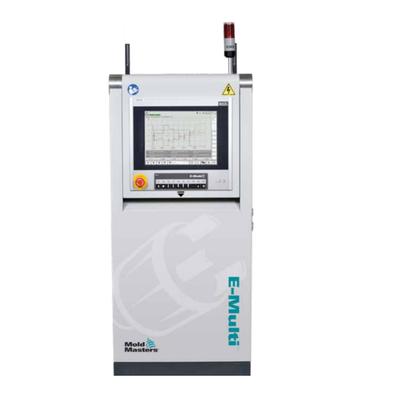
OVERVIEW Section 4 - Overview 4.1 Controller Front 1. Lifting rings 2. Alarm indicator light 3. Human machine interface (HMI) 4. Emergency stop button Figure 4-1 Controller front E-Multi Controller User Manual © 2020 Mold-Masters (2007) Limited. All Rights Reserved. -
Page 44: Controller Back - Connections Side
6. E67 connection to robot. Jumper plug installed. 7. Bypass switch 8. Auxiliary injection unit connection 9. Main on / off power switch (circuit breaker) Figure 4-2 Controller back connections Figure 4-3 Diagnostic kit (option) © 2020 Mold-Masters (2007) Limited. All Rights Reserved. E-Multi Controller User Manual... -
Page 45: Cable Holders
They can be attached to the back of the cabinet to use for cable storage. See Figure 4-5. Cable holders attach to rear of cabinet Figure 4-5 Attach cable holders E-Multi Controller User Manual © 2020 Mold-Masters (2007) Limited. All Rights Reserved. - Page 46 OVERVIEW © 2020 Mold-Masters (2007) Limited. All Rights Reserved. E-Multi Controller User Manual...
-
Page 47: Section 5 - Installation
Refer to the serial plate on the controller cabinet for confirmation of the supply requirements. If the local supply is outside the specified range, please contact Mold-Masters for advice. WARNING - ELECTRICAL SHOCK HAZARD It is crucial to comply with these warnings to minimize any personal danger. -
Page 48: Connect The Controller To The E-Multi
E67 connector on the controller. If an SPI robot is to be used, attach the optional ROBOT SPI ADAPTER to the ROBOT E67 connector on the controller, and connect the robot’s SPI cable into the ROBOT SPI ADAPTER. © 2020 Mold-Masters (2007) Limited. All Rights Reserved. E-Multi Controller User Manual... -
Page 49: Connect The Controller To The Molding Machine
8. Bypass switch 9. Auxiliary injection unit connection 10. Main On / Off power switch (circuit breaker) 11. Heat exchanger power Figure 5-3 E-Multi connection locations EM4 Controller side connections E-Multi Controller User Manual © 2020 Mold-Masters (2007) Limited. All Rights Reserved. -
Page 50: Connect A Handheld Hmi (Optional)
2. Connect the other end of the crossover cable to the Ethernet port on the diagnostic computer. Note that the diagnostic computer may differ from the one shown. © 2020 Mold-Masters (2007) Limited. All Rights Reserved. E-Multi Controller User Manual... -
Page 51: Figure 5-5 Wireless Network Icon
The diagnostic computer must be connected to the internet using its wireless network adapter. The wired connection must be used to connect to the controller. Mold-Masters does not support alternate network configurations. Connection problems when using alternate configurations are not covered under warranty and may result in increased support times and additional costs. -
Page 52: Section 6 - Operation
You can use a suitably-sized padlock, or similar device to lock the switch in the off position to lockout electrical supply during maintenance. Figure 6-1 E-Multi main power switch E-Multi Controller User Manual © 2020 Mold-Masters (2007) Limited. All Rights Reserved. -
Page 53: Switch On
The E-Multi controller can be used in Manual, Setup and Auto/Ready mode. 6.4 Switch Off (Shutdown) Mold-Masters recommends that you use the console to shutdown the heating load, and only use the main current breaker switch to turn off the dormant controller. -
Page 54: Section 7 - E-Multi Controller Hmi Interface
Control the password protection on all settings. • Print out any displays or data listings. • Connect and monitor Euromap connection between the E-Multi, molding machine and robot. E-Multi Controller User Manual © 2020 Mold-Masters (2007) Limited. All Rights Reserved. -
Page 55: Cabinet Mounted Control Buttons
No motion will occur if this button is not lit up. © 2020 Mold-Masters (2007) Limited. All Rights Reserved. E-Multi Controller User Manual... -
Page 56: E-Multi Touchscreen Interface
Overview, Valve Gate Settings, Injection at the top and touch buttons below Settings, Hold Settings, Recovery Settings, etc. that give quick access to commonly used functions. Some buttons will be screen specific. E-Multi Controller User Manual © 2020 Mold-Masters (2007) Limited. All Rights Reserved. -
Page 57: Top Bar - Status Display
User Level Shows current user and current user access level. Mode and Status Window Shows what systems are active, their status and if any alarms are present. © 2020 Mold-Masters (2007) Limited. All Rights Reserved. E-Multi Controller User Manual... -
Page 58: Active Movement Icons
Set up Mode. Machine jogs at set up speed. Automatic Mode. Machine will operate automatically when the molding machine provides the proper trigger and the EuroMap connections from the molding machine and robot are correct. E-Multi Controller User Manual © 2020 Mold-Masters (2007) Limited. All Rights Reserved. -
Page 59: Bottom Bar - Screen Navigation Buttons
Takes the user to the alarm screen which displays a list of alarms triggered by the control system. Back Button Returns to the screen that was previously displayed. © 2020 Mold-Masters (2007) Limited. All Rights Reserved. E-Multi Controller User Manual... -
Page 60: Print Functionality
Output to a file. MIME Type Selection of a MIME-type for the output file. Directory Target directory for the output file. Filename File name of the output file. E-Multi Controller User Manual © 2020 Mold-Masters (2007) Limited. All Rights Reserved. -
Page 61: Screen Descriptions
Profile Settings → Drive Parameter Monitor → PID Settings → Machine Data → Variable Monitor → Delay Settings → Calibration Settings Alarm Display Mold Data Screen Euromap 67 Screen © 2020 Mold-Masters (2007) Limited. All Rights Reserved. E-Multi Controller User Manual... -
Page 62: Overview Screen
7.5 Overview Screen This screen serves as a standard display in ongoing production operation and provides operating personnel with an overview of the machine’s key data. Figure 7-3 Overview screen E-Multi Controller User Manual © 2020 Mold-Masters (2007) Limited. All Rights Reserved. -
Page 63: Table 7-7 Overview Screen Components
(fully forward). An analog bar shows the current position graphically. Markers to the left and right of the analog bar indicate when the end position is reached. © 2020 Mold-Masters (2007) Limited. All Rights Reserved. E-Multi Controller User Manual... - Page 64 (empty) if the input or output is off. Green - signal is logical true Empty - signal is logical false E-Multi Controller User Manual © 2020 Mold-Masters (2007) Limited. All Rights Reserved.
-
Page 65: Table 7-8 Overview Screen Context Menu Buttons
This screen also displays system information like current user, software version, and IP addresses. See “System Settings Screen” on page 7-61. © 2020 Mold-Masters (2007) Limited. All Rights Reserved. E-Multi Controller User Manual... -
Page 66: Injection Settings Screen
(in case of stage 1, the end position of the previous part movement) and the position specified under the 'To' column. The last step will complete when one of the transition conditions is met. E-Multi Controller User Manual © 2020 Mold-Masters (2007) Limited. All Rights Reserved. - Page 67 It is used to prevent transition when injection pressure spikes at the start of injection. Note: This field is only available when transition on injection pressure is selected. © 2020 Mold-Masters (2007) Limited. All Rights Reserved. E-Multi Controller User Manual...
-
Page 68: Table 7-10 Injection Settings Screen Context Menu Buttons
Pressure, Velocity and Time for the intrusion (screw rotation before Inject). Table 7-10 Injection Settings Screen Context Menu Buttons Motor or Drive Information Screen Production Graph - Configurable View Production Settings Reference Settings E-Multi Controller User Manual © 2020 Mold-Masters (2007) Limited. All Rights Reserved. -
Page 69: Hold Settings Screen
Velocity between the end position of the previous stage (in case of stage 1, the end position of the previous part movement) and the position specified under the 'To' column. © 2020 Mold-Masters (2007) Limited. All Rights Reserved. E-Multi Controller User Manual... -
Page 70: Table 7-12 Hold Settings Screen Context Menu Buttons
(white) field. Table 7-12 Hold Settings Screen Context Menu Buttons Production Graphs Navigates to the Production Graph screen which provides real time data on the current production process. E-Multi Controller User Manual © 2020 Mold-Masters (2007) Limited. All Rights Reserved. -
Page 71: Recovery Settings Screen
Charge between the end position of the previous stage (in case of stage 1, the end position of the previous part movement) and the position specified under the 'To' column. © 2020 Mold-Masters (2007) Limited. All Rights Reserved. E-Multi Controller User Manual... - Page 72 Specifies the amount of time the vibration is on within the on / off cycle. Off Time Specifies the amount of time the vibration is off within the on / off cycle. E-Multi Controller User Manual © 2020 Mold-Masters (2007) Limited. All Rights Reserved.
-
Page 73: Table 7-14 Recovery Settings Screen Context Menu Buttons
Table 7-14 Recovery Settings Screen Context Menu Buttons Production Graphs Navigates to the Production Graph Screen which provides real time data on the current production process. © 2020 Mold-Masters (2007) Limited. All Rights Reserved. E-Multi Controller User Manual... -
Page 74: Barrel Temperature Settings - Legacy Controllers
If this tolerance is exceeded an alarm will be triggered. Only when all zones are within the tolerance is movement of the screw possible. E-Multi Controller User Manual © 2020 Mold-Masters (2007) Limited. All Rights Reserved. -
Page 75: Table 7-16 Legacy Style Barrel Temperature Setting Screen Context Menu Buttons
This feature is not required for standard configurations. Table 7-16 Legacy Style Barrel Temperature Setting Screen Context Menu Buttons Reference Settings © 2020 Mold-Masters (2007) Limited. All Rights Reserved. E-Multi Controller User Manual... -
Page 76: Barrel Temperature Settings - Mold-Masters Screen
7-23 7.10 Barrel Temperature Settings - Mold-Masters Screen This screen is used to adjust temperature settings for the barrel heating zones. Figure 7-8 Mold-Masters barrel temperature settings screen E-Multi Controller User Manual © 2020 Mold-Masters (2007) Limited. All Rights Reserved. -
Page 77: Table 7-17 Mold-Masters Barrel Temperature Screen Components
Tol Lo Specifies the temperature below which the zone will be out of tolerance. If the temperature drops below this value, an alarm is triggered. © 2020 Mold-Masters (2007) Limited. All Rights Reserved. E-Multi Controller User Manual... -
Page 78: Table 7-18 Mold-Masters Temperature Settings Screen Context Menu Buttons
Off: temperature is reset to the production operating temperatures. Screw movement is possible. Table 7-18 Mold-Masters Temperature Settings Screen Context Menu Buttons Hot Runner Control Setup Screen Navigates to the Integrated Hot Runner Control Setup screen where integrated hot runner control settings can be adjusted. -
Page 79: Integrated Hot Runner Temperature Control (Option)
Hot Runner Control Utilities Screen Figure 7-9 Integrated hot runner controller overview screen Lower Bar - E-Multi Screen Navigation and System Buttons See “Bottom Bar - Screen Navigation Buttons” on page 7-6. © 2020 Mold-Masters (2007) Limited. All Rights Reserved. E-Multi Controller User Manual... -
Page 80: Monitor Screen
Table 7-19 Monitor Screen Control Buttons [Run] switches on all heat zones, so that they independently rise up to their set point temperatures. [Stop] switches off all heat zones. E-Multi Controller User Manual © 2020 Mold-Masters (2007) Limited. All Rights Reserved. - Page 81 Black lettering on a on a black yellow background: background: Temperature zone Temperature is heating. within range. White lettering on a red background: Fatal error or temperature exceeds alarm limits. © 2020 Mold-Masters (2007) Limited. All Rights Reserved. E-Multi Controller User Manual...
- Page 82 For more information see “Slaving Zones” on page 7-30. 3. Use the number keys to enter the set point value. 4. Tap [Enter] to save the set point value in the controller. E-Multi Controller User Manual © 2020 Mold-Masters (2007) Limited. All Rights Reserved.
- Page 83 5. When a zone is slaved its temperature readout will be replaced with SLAVE. A slave zone will be identified along with the zone it is slaved to (see below). © 2020 Mold-Masters (2007) Limited. All Rights Reserved. E-Multi Controller User Manual...
-
Page 84: Setup Screen (Supervisor Level)
The first column displays all the heat zones detected on the controller. This column is used to select heat zones in order to change their parameters. Zone parameters are identified by colored column headings. E-Multi Controller User Manual © 2020 Mold-Masters (2007) Limited. All Rights Reserved. - Page 85 2. Tap the parameter column. 3. Tap the [Set] button to display the keypad. 4. Set the value. Tap [Enter] to save the new parameter setting in the controller. © 2020 Mold-Masters (2007) Limited. All Rights Reserved. E-Multi Controller User Manual...
- Page 86 Once auto detection completes, the setup area will be populated with heater zones. The number of zones detected should always be an even number. 3. To setup zone types: a) Tap the first zone of the same type. E-Multi Controller User Manual © 2020 Mold-Masters (2007) Limited. All Rights Reserved.
- Page 87 6. Tap [OK]. 7. Refer to the hot runner wiring diagram for a table showing heater type and position of each zone. A sample table is shown for reference: © 2020 Mold-Masters (2007) Limited. All Rights Reserved. E-Multi Controller User Manual...
-
Page 88: Utilities Screen (Supervisor Level)
The Utilities screen can only be accessed by supervisor credentials or above level authorized personnel. See the electrical schematic for further information. Figure 7-12 Utilities screen (supervisor level) E-Multi Controller User Manual © 2020 Mold-Masters (2007) Limited. All Rights Reserved. -
Page 89: Table 7-21 Utility Screen Elements
Tap the [Enabled] box and an interlock window will open. Tap the checkmark to enable the interlock. The status (On = green) / (Off = white) and PLC address is displayed on the right. © 2020 Mold-Masters (2007) Limited. All Rights Reserved. E-Multi Controller User Manual... -
Page 90: Integrated E-Drive Control (Option)
E-Drive Plate. Figure 7-13 E-Drive control screen components Lower Bar - E-Multi Screen Navigation and System Buttons See “Bottom Bar - Screen Navigation Buttons” on page 7-6 . E-Multi Controller User Manual © 2020 Mold-Masters (2007) Limited. All Rights Reserved. -
Page 91: E-Drive Control Buttons
Position is ignored. Only available in setup mode. Servo Drive Management functions. Servo State - used to turn the E-Drive servo drive on and off. Button will be green when servos are enabled. © 2020 Mold-Masters (2007) Limited. All Rights Reserved. E-Multi Controller User Manual... -
Page 92: Overview Screen
The [Start Opening Trigger] is selected from the drop down list. See Trigger Configuration. A time delay may also be added. The [Set Velocity] button opens a dialog where users may further adjust settings. E-Multi Controller User Manual © 2020 Mold-Masters (2007) Limited. All Rights Reserved. -
Page 93: Homing
Goes to the Integrated Hot Runner Control Setup screen where Integrated Hot Runner Control settings can be adjusted. E-Drive Settings Screen Goes to the E-Drive Settings screen where settings can be adjusted. Production Graph - Customizable view. © 2020 Mold-Masters (2007) Limited. All Rights Reserved. E-Multi Controller User Manual... -
Page 94: Settings Screen (Supervisor Level)
However, if Master mode is used, any slaved plates will not be accessible on the right, only master plates. Figure 7-15 E-Drive setting screen E-Multi Controller User Manual © 2020 Mold-Masters (2007) Limited. All Rights Reserved. -
Page 95: Table 7-25 E-Drive Settings Screen Elements
Enabled - check to enable Time setting after which it times out. Idle too long in Auto Mode? (set timeout) Exit from Auto mode after the specified period of inactivity. © 2020 Mold-Masters (2007) Limited. All Rights Reserved. E-Multi Controller User Manual... -
Page 96: Valve Gate Settings Screen
7.15 Valve Gate Settings Screen This screen is used to control individual valve gates, typically for single acting solenoids in pneumatic or hydraulic systems. Figure 7-16 Valve gate settings screen E-Multi Controller User Manual © 2020 Mold-Masters (2007) Limited. All Rights Reserved. -
Page 97: Table 7-26 Valve Gate Settings Screen Elements
Current Status A green indicator box shows whether the valve gate is currently open or closed. © 2020 Mold-Masters (2007) Limited. All Rights Reserved. E-Multi Controller User Manual... -
Page 98: Shutoff-Nozzle Settings Screen
When sensors are not present, the watchdog timers change to move timers. These timers add a delay to the process to allow the shutoff nozzle to open or close before the process continues. E-Multi Controller User Manual © 2020 Mold-Masters (2007) Limited. All Rights Reserved. - Page 99 With Sensors The Output indicators show the status of the PLC outputs to the hydraulic or pneumatic valve. The Input indicators show the status of the sensors. © 2020 Mold-Masters (2007) Limited. All Rights Reserved. E-Multi Controller User Manual...
- Page 100 The shutoff nozzle cannot be operated manually when the system is in automatic mode. The servo motors must be on (F10 LED on). E-Multi Controller User Manual © 2020 Mold-Masters (2007) Limited. All Rights Reserved.
-
Page 101: Shutoff-Nozzle Settings Screen-Kortec
The Output indicators show the status of the PLC outputs to the hydraulic or pneumatic valve. The Input indicators show the status of the sensors. Without Sensors Only the Output indicators are shown. © 2020 Mold-Masters (2007) Limited. All Rights Reserved. E-Multi Controller User Manual... - Page 102 IMM position in real time. Delay—Open Adds a delay of the specified time after the open trigger turns on. Delay time is ignored if the shutoff nozzle is set to Always Open. E-Multi Controller User Manual © 2020 Mold-Masters (2007) Limited. All Rights Reserved.
- Page 103 If a recovery delay is used the recovery delay is added after this delay. Delay time is ignored if the shutoff nozzle is set to Always Open. © 2020 Mold-Masters (2007) Limited. All Rights Reserved. E-Multi Controller User Manual...
-
Page 104: Production Graph Screen
Menu buttons at the bottom of the screen provide access to other settings (Setup, Zoom, View, Tolerances, etc.). Figure 7-19 Production graph screen Lower Button - Default Production Graph View E-Multi Controller User Manual © 2020 Mold-Masters (2007) Limited. All Rights Reserved. - Page 105 Production data Supervisor settings PD - Histogram Production data in histogram format PD - Scatter Graph Production data in scatter graph format PD - Cycle Time Production data on cycle time © 2020 Mold-Masters (2007) Limited. All Rights Reserved. E-Multi Controller User Manual...
-
Page 106: Lower Menu Buttons
File Start Export: Starts the export of the current curve to a file. Load Measurement: Opens a saved measurement and shows the variable values in the diagram. E-Multi Controller User Manual © 2020 Mold-Masters (2007) Limited. All Rights Reserved. -
Page 107: Software Oscilloscope
Interval Displays the time period between two measurements (seconds). This is automatically calculated by the system. Scroll Range Defines the area for scrolling around the fully drawn graphic. © 2020 Mold-Masters (2007) Limited. All Rights Reserved. E-Multi Controller User Manual... -
Page 108: Trigger
> Adds the highlighted variable from the process parameter list to the selection list. < Removes the highlighted element from the selection list. << Removes all elements from the selection list. E-Multi Controller User Manual © 2020 Mold-Masters (2007) Limited. All Rights Reserved. -
Page 109: Line Color
E-MULTI CONTROLLER HMI INTERFACE 7-56 7.19.4 Line Color Line color selection for displayed curves. © 2020 Mold-Masters (2007) Limited. All Rights Reserved. E-Multi Controller User Manual... -
Page 110: Process Data (Pd) Protocol Screen
The number of cycles (injections) that are taken into account can be adjusted. The default is 20 cycles. E-Multi Controller User Manual © 2020 Mold-Masters (2007) Limited. All Rights Reserved. -
Page 111: Lower Menu Buttons
PD - Histogram Production data in histogram format PD - Scatter Graph Production data in scatter graph format PD - Cycle Time Process cycle time shown in stacked horizontal bars © 2020 Mold-Masters (2007) Limited. All Rights Reserved. E-Multi Controller User Manual... -
Page 112: Main Settings Screen
This screen serves as a central access point for configuration screens as well as service and maintenance screens. The functions available are determined by the user access level. Figure 7-23 Main setting screen E-Multi Controller User Manual © 2020 Mold-Masters (2007) Limited. All Rights Reserved. - Page 113 Each screen will be given a high level description in the pages that follow. If you need a more detailed description of the functionality, please contact your Mold-Masters representative. Figure 7-24 Machine specification screen icons © 2020 Mold-Masters (2007) Limited. All Rights Reserved. E-Multi Controller User Manual...
-
Page 114: System Settings Screen
Screen saver Sets the time after which the HMI screen will be turned off. Auto Logout Sets the time after which a logged-on user is automatically logged off. E-Multi Controller User Manual © 2020 Mold-Masters (2007) Limited. All Rights Reserved. - Page 115 Spooler Shows the number of pending Dialog print jobs Device IP Shows the IP address of the visualization system Host IP Shows the IP address of the controller © 2020 Mold-Masters (2007) Limited. All Rights Reserved. E-Multi Controller User Manual...
-
Page 116: Lower Menu Buttons
Note: An operator may be asked to save a status report for troubleshooting purposes. Masks (Screens) Shows additional diagnostic screens by selecting them in the dialog and pressing the confirmation button. E-Multi Controller User Manual © 2020 Mold-Masters (2007) Limited. All Rights Reserved. -
Page 117: E-Multi Radial / Servo Carriage Screen
1 controls the movement in the first stage, when the nozzle is moving towards the mold, and the field labeled end controls the nozzle movement when the nozzle is making contact with the mold. © 2020 Mold-Masters (2007) Limited. All Rights Reserved. E-Multi Controller User Manual... - Page 118 Table 7-39 E-Multi Radial / Servo Carriage Screen Context Menu Buttons Auto Purge See “Auto Purge Screen” on page 7-66. E-Multi Controller User Manual © 2020 Mold-Masters (2007) Limited. All Rights Reserved.
-
Page 119: Auto Purge Screen
7.24 Auto Purge Screen This screen is used to setup and activate the Auto Purge program for the E-Multi Radial / Servo carriage system. Figure 7-28 Auto purge screen © 2020 Mold-Masters (2007) Limited. All Rights Reserved. E-Multi Controller User Manual... - Page 120 Auto Purge Start / Stop Pressing the 'Start' button with activate the Auto Purge program. Pressing the 'Stop' button will deactivate the Auto Purge process before it is complete. E-Multi Controller User Manual © 2020 Mold-Masters (2007) Limited. All Rights Reserved.
-
Page 121: Info-Log Screen
Using the menu bar, the entire info log may be saved or printed out. The list may be limited to specific system events using the aid of a filter. This makes it easier to find entries. © 2020 Mold-Masters (2007) Limited. All Rights Reserved. E-Multi Controller User Manual... - Page 122 OK. from / to A specified time period may be entered in these input fields which restricts the Info-Log entries displayed. Confirm the entries. E-Multi Controller User Manual © 2020 Mold-Masters (2007) Limited. All Rights Reserved.
-
Page 123: Programmable I/O
Which variable will be used to turn the output on or off. The drop down list displays the variables in the IO Param variable group. Additional variables may be added as required. © 2020 Mold-Masters (2007) Limited. All Rights Reserved. E-Multi Controller User Manual... - Page 124 A module of 2 on the ON condition would require the ON condition to be fulfilled 2 times before the output was turned on. E-Multi Controller User Manual © 2020 Mold-Masters (2007) Limited. All Rights Reserved.
-
Page 125: I/O Monitor Screen
Switches to the detail view of the selected module. Start / Stop Indicator The state of the CPU is displayed as follows: CPU is started. CPU is stopped. © 2020 Mold-Masters (2007) Limited. All Rights Reserved. E-Multi Controller User Manual... -
Page 126: Production Settings Screen
Unit Setup Button Displays the measurement unit settings dialog. This dialog can be used to change the measurement units for the system and save or load custom unit templates. E-Multi Controller User Manual © 2020 Mold-Masters (2007) Limited. All Rights Reserved. -
Page 127: Drive Monitor Screen
Initialization status of the drive (display only) • Green = Drive is initialized and ready for operation • Empty = Drive is not initialized / ready for operation © 2020 Mold-Masters (2007) Limited. All Rights Reserved. E-Multi Controller User Manual... - Page 128 The current status of referencing is shown in a text line to the right of this button. Status Display The status display of the drive is to the right of the button Start referencing. The states are shown in text form, e.g. Referenced. E-Multi Controller User Manual © 2020 Mold-Masters (2007) Limited. All Rights Reserved.
-
Page 129: Task Monitor Screen
E-MULTI CONTROLLER HMI INTERFACE 7-76 7.29 Task Monitor Screen This screen shows software tasks that are running in the background. Figure 7-34 Task monitor screen © 2020 Mold-Masters (2007) Limited. All Rights Reserved. E-Multi Controller User Manual... -
Page 130: Drive Parameter Monitor Screen
The file name can also be specified besides the storage location. SPS -> Drive The entire parameter set from a file (*.vda) may be loaded into the selected drive here. E-Multi Controller User Manual © 2020 Mold-Masters (2007) Limited. All Rights Reserved. -
Page 131: Pid Settings
The proportional part for the back pressure at plasticizing is Backpressure adjusted here. The integral part for the back pressure at plasticizing is adjusted here. The differential part for the back pressure at plasticizing is adjusted here. © 2020 Mold-Masters (2007) Limited. All Rights Reserved. E-Multi Controller User Manual... -
Page 132: Reference Settings Screen
Reference Tap the button to reset the nozzle position to 0 when the nozzle is just touching the nozzle inlet on the mold. E-Multi Controller User Manual © 2020 Mold-Masters (2007) Limited. All Rights Reserved. -
Page 133: Reference Settings Screen - Continued
Note: Referencing should be done with no material in the feed block to prevent material bridging. Table 7-51 Reference Settings Screen Context Menu Buttons Production Graph Configurable view Production Settings © 2020 Mold-Masters (2007) Limited. All Rights Reserved. E-Multi Controller User Manual... -
Page 134: Machine Data Screen
This button is only available if machine data has already been saved. Restore Backup Restores the saved machine file. This button is only available if a backup is available. E-Multi Controller User Manual © 2020 Mold-Masters (2007) Limited. All Rights Reserved. -
Page 135: Variable Monitor Screen
The variables monitor consists of three sections (tabs): • Variable selection, for grouping of variables • Variable list, for displaying selected variables • Search result Figure 7-38 Variable monitor screen © 2020 Mold-Masters (2007) Limited. All Rights Reserved. E-Multi Controller User Manual... - Page 136 The long text is displayed with the option Display Variable Text. Value Displays the value of the variable. The value can be modified directly. Unit Unit of the variable. E-Multi Controller User Manual © 2020 Mold-Masters (2007) Limited. All Rights Reserved.
-
Page 137: Delay Settings Screen
The duration between the plasticizing and the start of the nozzle's Forward Delay forward movement is specified here. The duration between the end of injecting and the start of the nozzle's Backward Delay backward movement is specified here. © 2020 Mold-Masters (2007) Limited. All Rights Reserved. E-Multi Controller User Manual... -
Page 138: Calibration Settings Screens
1 - n After the auto calibration, the values determined in the process will be entered automatically into these fields. All values can be subsequently changed by manual entry. E-Multi Controller User Manual © 2020 Mold-Masters (2007) Limited. All Rights Reserved. -
Page 139: Alarms Screen
The alarm screen shows a list of the alarms triggered by the control including status, time of occurrence, alarm class and description. Alarms can be confirmed either individually or collectively via the menu bar. Figure 7-41 Alarms screen © 2020 Mold-Masters (2007) Limited. All Rights Reserved. E-Multi Controller User Manual... - Page 140 To acknowledge all alarms it is not necessary to select the alarms. Alarm History Shows the history of alarms. Help This button can call up an alarm help for a selected alarm line. E-Multi Controller User Manual © 2020 Mold-Masters (2007) Limited. All Rights Reserved.
-
Page 141: Mold Data Screen
Currently loaded mold mold data settings. Drive Selection of a drive (local compact flash or USB stick) for saving and loading mold settings. Comment Comments about the current mold settings. © 2020 Mold-Masters (2007) Limited. All Rights Reserved. E-Multi Controller User Manual... -
Page 142: Lower Menu Buttons
In the case where a standard mold setting file was loaded, loading a E-Radial mold setting file will correct the profile. E-Multi Controller User Manual © 2020 Mold-Masters (2007) Limited. All Rights Reserved. -
Page 143: Euromap E67 Screen
2. If the option for ‘Reject Tracking’ is selected in Factory settings and if there is an E-Multi alarm. 3. If SPC is being used and there is a bad part detected. © 2020 Mold-Masters (2007) Limited. All Rights Reserved. E-Multi Controller User Manual... -
Page 144: Legacy E67 Screen
E-MULTI CONTROLLER HMI INTERFACE 7-91 7.40 Legacy E67 Screen NOTE Displayed only on older systems. E-Multi Controller User Manual © 2020 Mold-Masters (2007) Limited. All Rights Reserved. -
Page 145: Section 8 - Maintenance
The surface is not resistant to 40% sodium hydroxide which will cause white discoloration of the screen. 8.2 Preventative Maintenance Table 8-1 Preventive Maintenance Schedule Preventive Maintenance Frequency Controller fan filters Check monthly, replace if necessary E-Multi Controller User Manual © 2020 Mold-Masters (2007) Limited. All Rights Reserved. -
Page 146: Verify Injection Pressure Oil Circuit (Preload Pressure)
5. Navigate to the screw settings page. Verify that the actual voltage is within the limits. Refer to the Engineering Specification Document for the respective size for specifications. © 2020 Mold-Masters (2007) Limited. All Rights Reserved. E-Multi Controller User Manual... -
Page 147: Nozzle Protrusion Adjustment - Automatic Adjustment
9. Press and hold the [F4] button to move the nozzle towards the mold until it stops. Verify that the contact force is equal to or slightly greater than the set point chosen in step 6. E-Multi Controller User Manual © 2020 Mold-Masters (2007) Limited. All Rights Reserved. -
Page 148: Automatic Calibration
Once the adjustment is made, press the [Start] button again to run the calibration routine again. Figure 8-1 Nozzle protrusion adjustment - Radial and Servo carriage models © 2020 Mold-Masters (2007) Limited. All Rights Reserved. E-Multi Controller User Manual... -
Page 149: Injection Axis Referencing
Once the dialog is confirmed, the injection axis will move automatically. 5. Wait for the screw to move fully back and then fully forward. Referencing is complete when the screw position is just below 0. E-Multi Controller User Manual © 2020 Mold-Masters (2007) Limited. All Rights Reserved. -
Page 150: Service And Repair The Controller
8.6.1 Replacement Parts Mold-Masters does not expect that you will need to repair any controller parts at board level other than fuses. In the unlikely event of any board failure then we provide an excellent repair and exchange facility for all our customers. -
Page 151: Update Software
MAINTENANCE 8.7 Update Software It is not necessary to send your control system back to the Mold-Masters factory for upgrades. Instead they will, on request, be sent to you in the form of one compact flash card that can be read by your controller. The following instructions will guide you through the upgrade procedure. -
Page 152: Save Machine Data
7. Repeat this procedure for each mold data file to be saved. 8.7.2 Save Machine Data 1. Insert a USB key into the USB port located on the side of the controller. 2. Navigate to the machine data screen. © 2020 Mold-Masters (2007) Limited. All Rights Reserved. E-Multi Controller User Manual... -
Page 153: Install New Software
PLC. 4. Insert the USB key with the machine and mold data backup files. E-Multi Controller User Manual © 2020 Mold-Masters (2007) Limited. All Rights Reserved. - Page 154 8. Navigate to the Mold Data screen. Select USB0 from the drop down menu, then tap the Load Mold Data button. 9. Navigate to the Heat set up page. Follow the button sequence below to select the Auto Detect button. © 2020 Mold-Masters (2007) Limited. All Rights Reserved. E-Multi Controller User Manual...
- Page 155 6-2 to complete the software upgrade. NOTE E-Multi controllers support only FAT or FAT32 formatted USB drives. USB drives formatted as NTFS, HFS(+), or EXT will not work. E-Multi Controller User Manual © 2020 Mold-Masters (2007) Limited. All Rights Reserved.
-
Page 156: Section 9 - Troubleshooting
If there is no pressure, check the pneumatic connection to the machine. If there is pressure, close the valve, reconnect the air line to the valve and open the valve. E-Multi Controller User Manual © 2020 Mold-Masters (2007) Limited. All Rights Reserved. -
Page 157: Servo Motor Temperature Check
9.5 Servo Motor Temperature Check The motor warning and alarm temperatures are factory settings that can only be changed by a Mold-Masters technician. The default values are: Warning temperature: 75°C Alarm temperature: 80°C The E-Multi controller automatically disables the motors when the alarm temperature is reached. -
Page 158: Fault And Warning Messages
Check card for faults. position is not responding. NONE A Zone type appears not to be There is a communications problem. selected for the card. Try a replacement controller card. E-Multi Controller User Manual © 2020 Mold-Masters (2007) Limited. All Rights Reserved. - Page 159 If during the test procedure a temperature interaction is found between zones, this message is displayed. FAIL The zone under test has failed. The zone has passed testing. © 2020 Mold-Masters (2007) Limited. All Rights Reserved. E-Multi Controller User Manual...
-
Page 160: Index
Mold Data 7-82 New Software Installation 8-9 Overview Screen 7-9 Process Data (PD) Protocol Screen 7-51 Production Graph Screen 7-45 Recovery Settings Screen 7-18 Release Details, Document 1-1 E-Multi Controller User Manual © 2020 Mold-Masters (2007) Limited. All Rights Reserved. - Page 161 +86 512 86162882 e: singapore@moldmasters.com e: korea@moldmasters.com e: china@moldmasters.com INDIA JAPAN tel: +91 422 423 4888 tel: +81 44 986 2101 e: india@moldmasters.com e: japan@moldmasters.com www.moldmasters.com © 2020 Mold-Masters (2007) Limited. All Rights Reserved. E-Multi Controller User Manual...
Need help?
Do you have a question about the E-Multi EM1 and is the answer not in the manual?
Questions and answers