Table of Contents
Advertisement
Quick Links
Advertisement
Table of Contents

Related Manuals for Mold-Masters TempMaster M1 Plus Series


Summary of Contents for Mold-Masters TempMaster M1 Plus Series
- Page 1 User Manual version 6 Original Instructions...
- Page 3 REMOVE AND KEEP THIS SHEET SOMEWHERE SAFE Every machine leaves our factory with two levels of password protection. We recommend that you remove this sheet in order to establish your own security. User Password - unix System Password - linux...
-
Page 5: Table Of Contents
1.2 Release Details ....................1-1 1.3 Warranty Details ....................1-1 1.4 Returned Goods Policy ..................1-1 1.5 Movement or Resale of Mold-Masters Products or Systems ......1-1 1.6 Copyright ......................1-2 1.7 Units of Measure and Conversion Factors ............1-2 Section 2 - Global Support ..........2-1 2.1 Corporate Offices....................2-1... - Page 6 6.3 Change or Set Zone Temperatures ..............6-4 6.4 Change Modes ....................6-5 6.5 Control for Individually Selected Zones ..............6-6 6.6 More About Boost Mode ..................6-6 6.6.1 Manual Boost Display ................6-6 © 2021 Mold-Masters (2007) Limited. All Rights Reserved. M1 Plus Controller User Manual...
- Page 7 7.4.1 Change Test Parameters ................7-6 7.5 Run a Self Diagnostic Test .................7-6 7.6 System Diagnosis Results ..................7-8 7.7 Interpret the Test Results ..................7-8 7.7.1 Satisfactory Test ..................7-8 7.7.2 Unsatisfactory Test ..................7-8 © 2021 Mold-Masters (2007) Limited. All Rights Reserved. M1 Plus Controller User Manual...
- Page 8 9.1.2 Set Power Rail to Delta Configuration ............9-3 9.2 Filter Option ......................9-4 9.3 Alarm Output / Auxiliary Input ................9-4 9.4 USB Port ......................9-4 9.5 Standard Tool Connections ................9-5 9.6 Touchscreen Schematic ..................9-7 Index ..................I © 2021 Mold-Masters (2007) Limited. All Rights Reserved. M1 Plus Controller User Manual...
-
Page 10: Section 1 - Introduction
Mold-Masters representative. 1.4 Returned Goods Policy Please do not return any parts to Mold-Masters without pre-authorization and a return authorization number supplied by Mold-Masters. Our policy is one of continuous improvement and we reserve the right to alter product specifications at any time without giving notice. -
Page 11: Copyright
INTRODUCTION 1.6 Copyright © 2020 Mold-Masters (2007) Limited. All Rights Reserved. Mold-Masters ® and the Mold-Masters logo are trademarks of Mold-Masters. 1.7 Units of Measure and Conversion Factors NOTE The dimensions given in this manual are from original manufacturing drawings. -
Page 13: Section 2 - Global Support
South Korea El Marques, Queretaro C.P. 76246 fax: +39 049/5019951 tel: +82-31-431-4756 Mexico italy@moldmasters.com korea@moldmasters.com tel: +52 442 713 5661 (sales) tel: +52 442 713 5664 (service) mexico@moldmasters.com © 2021 Mold-Masters (2007) Limited. All Rights Reserved. M1 Plus Controller User Manual... -
Page 14: International Representatives
123308 Moscow 2310 Slovenska Bistrica Kemenskoe City Dnipropetrovsk Russia Slovenija Region 51935, Ukraine tel: +7 (495) 199-14-51 +386 59 969 117 tel: +38 (038) 277-82-82 moldmasters@system.com.ru info@picta.si moldmasters@parkgroup.com.ua © 2021 Mold-Masters (2007) Limited. All Rights Reserved. M1 Plus Controller User Manual... -
Page 15: Section 3 - Safety
SAFETY Section 3 - Safety 3.1 Introduction Please be aware that the safety information provided by Mold-Masters does not absolve the integrator and employer from understanding and following international and local standards for safety of machinery. It is the responsibility of the end integrator to integrate the final system, provide... -
Page 16: Safety Hazards
10. Area inside the guards and outside the mold area Front view with guards removed Front View with Guards Removed Figure 3-1 Injection molding machine hazard areas © 2021 Mold-Masters (2007) Limited. All Rights Reserved. M1 Plus Controller User Manual... - Page 17 Hazards due to reduction in mechanical strength of the plasticizing and / or injection cylinder due to overheating. Feed Opening Pinching and crushing between injection screw movement and housing. See Figure 3-1 area 6 © 2021 Mold-Masters (2007) Limited. All Rights Reserved. M1 Plus Controller User Manual...
- Page 18 Crush or impact hazards caused by the movement of the power operated Gate gates. Vapors and Gases Certain processing conditions and / or resins can cause hazardous fumes or vapors. © 2021 Mold-Masters (2007) Limited. All Rights Reserved. M1 Plus Controller User Manual...
-
Page 19: Operational Hazards
• Never perform any work on the mold machine unless the hydraulic pump has been stopped. • Check frequently for possible oil leaks / water leaks. Stop the machine and make repairs. © 2021 Mold-Masters (2007) Limited. All Rights Reserved. M1 Plus Controller User Manual... - Page 20 Failure to support the machine can result in severe injury or death. • Mold cable from the controller to the mold must be removed before servicing the mold. © 2021 Mold-Masters (2007) Limited. All Rights Reserved. M1 Plus Controller User Manual...
-
Page 21: General Safety Symbols
Warning – Slip, Trip or Fall Hazard Do not climb on equipment surfaces. Serious slip, trip, or fall injuries can result from personnel climbing on equipment surfaces. © 2021 Mold-Masters (2007) Limited. All Rights Reserved. M1 Plus Controller User Manual... -
Page 22: Wiring Check
/ or equipment. Failure to do wiring or connections properly will result in equipment failure. The use of Mold-Masters standard connections can help to eliminate the potential for wiring errors. Mold-Masters Ltd. cannot be responsible for damage caused by customer wiring and / or connection errors. -
Page 23: Lockout Safety
Burns from contact with hot parts, materials or equipment such as furnaces Fires and explosions Chemical exposures from gases or liquids released from pipelines © 2021 Mold-Masters (2007) Limited. All Rights Reserved. M1 Plus Controller User Manual... -
Page 24: Electrical Lockout
The last lock to be removed should be that of the person supervising the lockout and this responsibility should not be delegated. © Industrial Accident Prevention Association, 2008. © 2021 Mold-Masters (2007) Limited. All Rights Reserved. M1 Plus Controller User Manual... -
Page 25: Energy Forms And Lockout Guidelines
Shut off, lock (with chains, built- • Storage tanks and vessels in lockout devices, or lockout attachments) and tag valves. • Bleed off excess liquids or gases. • Blank lines as necessary. © 2021 Mold-Masters (2007) Limited. All Rights Reserved. M1 Plus Controller User Manual... -
Page 26: Grounded Earth Connection
Figure 3-2 Grounded earth connection - M1 Plus lid 3.9 Disposal WARNING Milacron Mold-Masters declines any responsibility for personal injury or personal damage arising from reuse of the individual components, if these parts are used other than for the original and proper intended purpose. -
Page 27: M1 Plus Controller User Hazards
The controller cabinet and touchscreen console should be installed in a clean dry environment where the ambient conditions do not exceed the following limits: • Temperature +5 to +45°C • Relative Humidity 90% (non-condensing) © 2021 Mold-Masters (2007) Limited. All Rights Reserved. M1 Plus Controller User Manual... -
Page 29: Section 4 - Overview
Temperature Control Closed loop (Auto) or open loop (Manual) with HR Method software Temperature Scale Celsius (Centigrade) or Fahrenheit Voltage Bandwidth Stable within (20% supply voltage swing) © 2021 Mold-Masters (2007) Limited. All Rights Reserved. M1 Plus Controller User Manual... -
Page 30: The Controller Cabinet
The DC power supplies for the cards, data communications and an alarm output relay are all provided by a single power supply unit. This is located on top of the upper chassis panel. © 2021 Mold-Masters (2007) Limited. All Rights Reserved. M1 Plus Controller User Manual... -
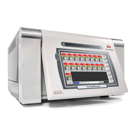
Page 31: Screen Layout
The Main page has a [Menu] button at the bottom of the side buttons that activates the navigation screen. All other pages use the [Back] button on the sidebar to return to the main page. © 2021 Mold-Masters (2007) Limited. All Rights Reserved. M1 Plus Controller User Manual... -
Page 32: Main Page
See Table 8-1 for a list of possible on red background. error messages. Zone Off Individual zone switched off. Different Header Colors User-configurable colors. © 2021 Mold-Masters (2007) Limited. All Rights Reserved. M1 Plus Controller User Manual... -
Page 33: Main Page - Display Options
4. Touch button again to show the Data page, which displays the setup and data for all of the zones. A fixed window below the scrolling pane displays the total current and total power. © 2021 Mold-Masters (2007) Limited. All Rights Reserved. M1 Plus Controller User Manual... -
Page 34: Main Page - Start, Stop And More Options
4.6 Main Page - Start, Stop and More Options Button 1 can appear as [Run/Stop] or [Startup/Shutdown]. Button 2 is [Mode]. Choose [Mode] to reveal all other Run mode options. © 2021 Mold-Masters (2007) Limited. All Rights Reserved. M1 Plus Controller User Manual... -
Page 35: More
[Config] button to setup system parameters - see “Configure the Control Cards” on page 5-4 • an [Export] function - see page 7-2 and a [QuadIO] button - see page 6-30 © 2021 Mold-Masters (2007) Limited. All Rights Reserved. M1 Plus Controller User Manual... - Page 36 OVERVIEW More Pages - continued The SetUp page is used to setup and configure various global and specific tool parameters. The Help pages offer user help. © 2021 Mold-Masters (2007) Limited. All Rights Reserved. M1 Plus Controller User Manual...
-
Page 37: The User Interface
Mode Keys – Auto, Manual and Slave, to set working mode Keypads 3 and 4 - offer more buttons to choose and configure synchro or spear tips © 2021 Mold-Masters (2007) Limited. All Rights Reserved. M1 Plus Controller User Manual... -
Page 38: Section 5 - Setup
Refer to the serial plate on the controller cabinet for confirmation of the supply requirements. If the local supply is outside the specified range, please contact Mold-Masters for advice. WARNING - ELECTRIC SHOCK HAZARD It is crucial to comply with these warnings to minimize any personal danger. -
Page 39: Setup The Console
Main page. 5.3 Create the First Tool 1. Choose [Menu] and open the Tool page. 2. Choose a blank tool slot and choose [Detect]. © 2021 Mold-Masters (2007) Limited. All Rights Reserved. M1 Plus Controller User Manual... -
Page 40: Cards That May Be Detected
5.4 Cards That May Be Detected Table 5-1 Cards That May Be Detected 6-zone card at 15 Amp rating for probes and manifolds Quad Input/Output card with programmable input and output options © 2021 Mold-Masters (2007) Limited. All Rights Reserved. M1 Plus Controller User Manual... -
Page 41: Configure The Control Cards
Choose the first zone, then the last zone, then choose [Range] to include all the zones in between, as shown below: 2. Choose [Set] to see the Configure Card Slot menu. © 2021 Mold-Masters (2007) Limited. All Rights Reserved. M1 Plus Controller User Manual... -
Page 42: Preconfigured Setup Values
0ºC or 0ºF blank Startup Stage T/C Offset Value 0ºC or 0ºF blank T/C Open Mode Normal blank Triac On-board blank Warn Hi and Lo 5ºC or 9ºF blank © 2021 Mold-Masters (2007) Limited. All Rights Reserved. M1 Plus Controller User Manual... -
Page 43: Configure The Controller
Parameters can have either: Value settings - use the [Edit] button to bring up a keypad to enter values Tick boxes - select or deselect the parameter © 2021 Mold-Masters (2007) Limited. All Rights Reserved. M1 Plus Controller User Manual... -
Page 44: Global Parameters
• If the cycling stops the Input Timer times out and the console goes to Stop. BOOST - switches the controller into Boost mode. © 2021 Mold-Masters (2007) Limited. All Rights Reserved. M1 Plus Controller User Manual... - Page 45 Sets an overall Standby temperature, which will override indi- The maximum Temp vidual Standby temperature settings. Standby • Leave this value set to 0° for individual standby values to Temperature is remain valid. 260° C. © 2021 Mold-Masters (2007) Limited. All Rights Reserved. M1 Plus Controller User Manual...
-
Page 46: Save The Configured Settings
Chooses [Degree C] or [Degree F] as required. 5.9 Save the Configured Settings 1. Choose [OK] to save all the configuration settings. 2. Choose [Cancel] to leave the page without making any changes. © 2021 Mold-Masters (2007) Limited. All Rights Reserved. M1 Plus Controller User Manual... -
Page 47: Set The Tool Parameters
SETUP 5-10 5.10 Set the Tool Parameters 1. Choose the zones. 2. Choose the parameter. 3. Choose [Set]. 4. Set the value. © 2021 Mold-Masters (2007) Limited. All Rights Reserved. M1 Plus Controller User Manual... -
Page 48: Tool Parameters
450°C or 842°F. Setting Minimum Sets the lowest permitted setpoint for the The lowest Minimum Setpoint Setpoint zone(s). temperature is 0°C or 0°F. Setting © 2021 Mold-Masters (2007) Limited. All Rights Reserved. M1 Plus Controller User Manual... - Page 49 Warning and Sets the first (Warning) and second (Alarm) The maximum Warning or Alarm Levels stage alarms. Alarm value is 99°C or 178°F. © 2021 Mold-Masters (2007) Limited. All Rights Reserved. M1 Plus Controller User Manual...
-
Page 50: Set The Operating Parameters
SETUP 5-13 5.12 Set the Operating Parameters 5.12.1 Choose Zones 1. Choose the first zone. 2. Choose the last zone. 3. Choose [Range]. 4. Choose [Set]. © 2021 Mold-Masters (2007) Limited. All Rights Reserved. M1 Plus Controller User Manual... -
Page 51: Set Probe And Manifold Temperatures
6. Choose [Ent] to confirm the settings or [Esc] to leave the page without making any changes. 5.12.2 Set Probe and Manifold Temperatures 1. Choose [Set]. 2. Choose [Auto]. © 2021 Mold-Masters (2007) Limited. All Rights Reserved. M1 Plus Controller User Manual... - Page 52 3. Set the temperature value or choose [Delete] to clear the last input.. 4. Choose [Ent] to confirm the settings or [Esc] to leave the page without making any changes. © 2021 Mold-Masters (2007) Limited. All Rights Reserved. M1 Plus Controller User Manual...
-
Page 53: Save Settings To The Tool Bank
It will update automatically if the software is upgraded. Please make a note of the software version date before you contact your supplier with any technical questions. © 2021 Mold-Masters (2007) Limited. All Rights Reserved. M1 Plus Controller User Manual... -
Page 54: Utilities Parameters
Password” on page 5-20 for more details. Edit User Sets the Level 1 password. See ”5.13.2 Edit the User Password” Password on page 5-20 for more details. © 2021 Mold-Masters (2007) Limited. All Rights Reserved. M1 Plus Controller User Manual... - Page 55 Defaults to SPI and is not user- installed and which will be used to configurable communicate with remote terminal. • can be set to Kistler protocol if requested when ordered. © 2021 Mold-Masters (2007) Limited. All Rights Reserved. M1 Plus Controller User Manual...
- Page 56 If set to [Disabled] then all the lower functions become available without the need for any password. Note: Only those higher functions that require a System (Level 2) password retain their password protection. © 2021 Mold-Masters (2007) Limited. All Rights Reserved. M1 Plus Controller User Manual...
-
Page 57: Password Security
99. This setting eliminates the need to enter a password at any of the usual checkpoints such as Load Tool or Temperature Change. The only function that will still require a password input is the Change Password action. © 2021 Mold-Masters (2007) Limited. All Rights Reserved. M1 Plus Controller User Manual... -
Page 58: Password Options
1 password or no password, then the System password will expire after 20 seconds. The user will still be able to access any page that requires a Level 1 password or no password. © 2021 Mold-Masters (2007) Limited. All Rights Reserved. M1 Plus Controller User Manual... -
Page 59: Password Application Table
Export / Exit (shut Load, Save, Backup New (Create new down console) Restore, Delete tools) Utils Set / Change Time Change any Utility values SetUp Set, Config (Change any values) © 2021 Mold-Masters (2007) Limited. All Rights Reserved. M1 Plus Controller User Manual... -
Page 60: Configure A Printer
6. Choose [Paper Size]. 7. Choose [Set] to see the Paper-size selection panel. 8. Choose [A4] or [Letter] and choose [OK]. 9. Choose [Back] to return to the Main page. © 2021 Mold-Masters (2007) Limited. All Rights Reserved. M1 Plus Controller User Manual... -
Page 61: More Utilities Function Buttons
This is a digital Input / Output card that offers up to four separate inputs and outputs to facilitate remote interaction with the controller. Refer to ““QCIO - 4-Channel Input / Output Card” on page 6-30 for setup instructions. © 2021 Mold-Masters (2007) Limited. All Rights Reserved. M1 Plus Controller User Manual... -
Page 62: Section 6 - Operation
(M1-48) or the breaker switch (M1-12 and 24) are only used to switch off a dormant controller. 1. Shut down the heating. On the Main page, choose [Stop] mode to reduce the heating to zero. © 2021 Mold-Masters (2007) Limited. All Rights Reserved. M1 Plus Controller User Manual... -
Page 63: Control Modes For All Zones
Choosing Stop mode does not remove voltage from the heaters. Do not try to change fuses or disconnect units while in this mode. These modes can be accessed from the Main page. © 2021 Mold-Masters (2007) Limited. All Rights Reserved. M1 Plus Controller User Manual... - Page 64 BOOST – temporarily raise the temperature and then return to normal Set Temperature. • STANDBY – lower zone temperatures until the Run command is given. STOP Button One or Switches off all zones. Mode Button © 2021 Mold-Masters (2007) Limited. All Rights Reserved. M1 Plus Controller User Manual...
-
Page 65: Change Or Set Zone Temperatures
To lower the overall temperature - Choose [Minus] 4. Enter the temperature setting or change. 5. Choose [Ent] to set the required temperature or [Esc] to leave the page without making any changes. © 2021 Mold-Masters (2007) Limited. All Rights Reserved. M1 Plus Controller User Manual... -
Page 66: Change Modes
To return to Auto mode - Choose [Auto] and enter the required zone temperature. 4. Choose [Ent] to set the required temperature or [Esc] to leave the page without making any changes. © 2021 Mold-Masters (2007) Limited. All Rights Reserved. M1 Plus Controller User Manual... -
Page 67: Control For Individually Selected Zones
The BOOST message displays until Boost time period expires, after which the zones returns to normal set temperature and the Mode window shows RUN. © 2021 Mold-Masters (2007) Limited. All Rights Reserved. M1 Plus Controller User Manual... -
Page 68: Remote Boost Display
The Purge function is only available while the tool is in Run mode, and it has two different options: 6.8.1 Mechanical Purge Mechanical purge guides the operator through four programmed steps to expel one color and to introduce a new color. © 2021 Mold-Masters (2007) Limited. All Rights Reserved. M1 Plus Controller User Manual... -
Page 69: Chemical Purge
Once the timer expires the operator chooses [Next] to continue with the final Mold step and quality checks. NOTE Choose [Exit] leave the Purge wizard at any time. © 2021 Mold-Masters (2007) Limited. All Rights Reserved. M1 Plus Controller User Manual... -
Page 70: Configure Purge Parameters
[Settings] from the Purge Mechanical or the wizard. Chemical purge • You may set Purge mode if you sequence. choose [Settings] at the pre-run panel. © 2021 Mold-Masters (2007) Limited. All Rights Reserved. M1 Plus Controller User Manual... -
Page 71: Record A Color Purge Cycle
At the end of a satisfactory purge run, the parameters are displayed along with an option to print them out. Choose [Exit] to leave the screen. 6.9 Check Zone Settings 1. Choose any zone. © 2021 Mold-Masters (2007) Limited. All Rights Reserved. M1 Plus Controller User Manual... -
Page 72: Graph A Zone's Past Performance
The controller can record the past 30 minutes of temperature history and display this information in a graph. 1. Choose up to six zones. 2. Choose [Graph]. © 2021 Mold-Masters (2007) Limited. All Rights Reserved. M1 Plus Controller User Manual... - Page 73 5. Use the four [Zoom] keys to expand time of temperature scales. Drag either scale to shift the display. NOTE Once any zoom is used the graph freezes in time and does not update. © 2021 Mold-Masters (2007) Limited. All Rights Reserved. M1 Plus Controller User Manual...
-
Page 74: Alarms
This can only be started in Run mode and then Yellow text in PURGE goes on to guide you through a typical color black box change routine. © 2021 Mold-Masters (2007) Limited. All Rights Reserved. M1 Plus Controller User Manual... -
Page 75: Status Window
Fatal Error This shows an abbreviated error The error message is white message. text on red background. For a list of error messages see Table 8-1. © 2021 Mold-Masters (2007) Limited. All Rights Reserved. M1 Plus Controller User Manual... -
Page 76: Beacon And Sounder Extension
Demo mode feeds every zone within the selected tool with a stream of pre- recorded temperature data. The console appears to be working, and it gives a real trace when the Graph page is selected. © 2021 Mold-Masters (2007) Limited. All Rights Reserved. M1 Plus Controller User Manual... -
Page 77: Select Demo Mode
Note its current connection setting. 2. Choose [Connection] and then [Set]. 3. Choose [Demo Mode] in the Select-Connection option box. 4. Accept the warning that this option will disable the console. © 2021 Mold-Masters (2007) Limited. All Rights Reserved. M1 Plus Controller User Manual... -
Page 78: Deselect Demo Mode
To leave Demo mode, do the reverse of the selection procedure. 1. Choose the current tool. 2. Choose [Connection] and [Set]. 3. Choose the original setting that was noted at step 2 while selecting Demo mode previously. © 2021 Mold-Masters (2007) Limited. All Rights Reserved. M1 Plus Controller User Manual... -
Page 79: Use The Toolstore Page
HRC- NET cards. The Connection column also provides a demo facility. See “6.13.1 About Demo Mode” on page 6-15 for more information. © 2021 Mold-Masters (2007) Limited. All Rights Reserved. M1 Plus Controller User Manual... -
Page 80: Create A New Tool
1. Choose a blank tool slot and then choose [Save]. 2. Use the keyboard and name the new tool. 3. Open the SetUp page. © 2021 Mold-Masters (2007) Limited. All Rights Reserved. M1 Plus Controller User Manual... -
Page 81: Rename An Existing Tool
6. Finish the changes required for the new tool, then return to the Tool page and choose [Save]. 6.16 Rename an Existing Tool 1. Choose the relevant tool tab. © 2021 Mold-Masters (2007) Limited. All Rights Reserved. M1 Plus Controller User Manual... - Page 82 OPERATION 6-21 Rename an Existing Tool - continued 2. Choose the [Set] button. 3. Edit the name. 4. Choose [Enter]. © 2021 Mold-Masters (2007) Limited. All Rights Reserved. M1 Plus Controller User Manual...
-
Page 83: Load Tool Settings Locally
Run mode has been disabled. See Allow ToolLoad in “Table 5-5 Utilities Parameters” on page 5-17. 3. Choose [OK] to save or [Cancel] to exit. © 2021 Mold-Masters (2007) Limited. All Rights Reserved. M1 Plus Controller User Manual... -
Page 84: Save Tool Settings (Remotely)
If the new settings are satisfactory, then they can be saved into the same tab in the ToolStore. 1. Choose the tool. 2. Choose [Save]. 3. Choose [OK]. © 2021 Mold-Masters (2007) Limited. All Rights Reserved. M1 Plus Controller User Manual... -
Page 85: Save Old And New Settings
ToolStore. 1. Choose a blank tool tab. 2. Choose [Save]. 3. Choose [OK]. 4. Type in a new tool name and choose [Ent]. © 2021 Mold-Masters (2007) Limited. All Rights Reserved. M1 Plus Controller User Manual... -
Page 86: Delete A Tool
Ensure that you are deleting the correct tool. 1. Choose the unwanted tool. 2. Choose [Delete]. 3. Choose [OK]. 4. Return to ToolStore page to check that unwanted tool has been deleted. © 2021 Mold-Masters (2007) Limited. All Rights Reserved. M1 Plus Controller User Manual... -
Page 87: Backup Tool Settings
1. Open the ToolStore page. 2. Insert memory stick and wait until it is ready to use. 3. Choose [Backup]. 4. Wait about 10 seconds, then remove memory stick. © 2021 Mold-Masters (2007) Limited. All Rights Reserved. M1 Plus Controller User Manual... -
Page 88: Backup One Selected Tool Setting
1. Insert memory stick and wait until it is ready to use. 2. Choose the tool to backup. 3. Choose [Backup]. 4. Wait about 10 seconds, then remove the memory stick. © 2021 Mold-Masters (2007) Limited. All Rights Reserved. M1 Plus Controller User Manual... -
Page 89: Restore Tool Settings
2. Insert the memory stick with the data and wait until it is ready to use. 3. Choose [Restore]. 4. Wait about 10 seconds, then remove the memory stick. © 2021 Mold-Masters (2007) Limited. All Rights Reserved. M1 Plus Controller User Manual... -
Page 90: Restore A Single Tool
1. Insert the memory stick, then wait until it is ready to use. 2. Choose the Tool tab. 3. Choose [Restore]. 4. Wait about 10 seconds, then remove the memory stick. © 2021 Mold-Masters (2007) Limited. All Rights Reserved. M1 Plus Controller User Manual... -
Page 91: Qcio - 4-Channel Input / Output Card
Puts the Controller into SHUTDOWN mode. Standby Puts the Controller into STANDBY mode. Startup Puts the Controller into STARTUP mode. Stop Puts the Controller into STOP mode. © 2021 Mold-Masters (2007) Limited. All Rights Reserved. M1 Plus Controller User Manual... -
Page 92: Outputs
Water Flow Output is given if any flow sensor gives a flow reading that deviates from its nominal setpoint enough to generate a second stage alarm. © 2021 Mold-Masters (2007) Limited. All Rights Reserved. M1 Plus Controller User Manual... -
Page 93: Default Input / Output Selection And Connector Pin Table
NC Contact 3 Input 4 Go to STOP Input 4 mode Input 4 NO Contact 4 MC Contact 4 Output 4 Spare / Inactive NC Contact 4 © 2021 Mold-Masters (2007) Limited. All Rights Reserved. M1 Plus Controller User Manual... -
Page 94: Section 7 - Maintenance
Prints out the whole SetUp page with all the current settings for the current tool. Graph Prints out an image of the current graph trace when it is not in any Closeup view mode. © 2021 Mold-Masters (2007) Limited. All Rights Reserved. M1 Plus Controller User Manual... -
Page 95: Export Facility
1. Insert a memory stick and wait until it is ready to use. 2. Choose Utilities page and choose [Export]. 3. Choose the [First Zone] and pick the first zone from the list. 4. Repeat for the [Last Zone]. © 2021 Mold-Masters (2007) Limited. All Rights Reserved. M1 Plus Controller User Manual... - Page 96 Performance data can be autoarchived. If the [Auto-Archive] option is on and a memory stick is left plugged into the console, then historic data is written to that memory stick every 30 minutes. © 2021 Mold-Masters (2007) Limited. All Rights Reserved. M1 Plus Controller User Manual...
-
Page 97: Check Touchscreen Alignment
3. Touch the center point of the crosshairs. • When you stop touching the screen, the crosshair target will move to another position. 4. Repeat until all five locations have been tested. © 2021 Mold-Masters (2007) Limited. All Rights Reserved. M1 Plus Controller User Manual... -
Page 98: Self Diagnostic Tests
3. Once the test is done, the routine tests the other zones until all have been completed. © 2021 Mold-Masters (2007) Limited. All Rights Reserved. M1 Plus Controller User Manual... -
Page 99: Change Test Parameters
The other panels on the page give feedback about how the test is progressing. 1. Open the Diagnose Page and choose [Config]. 2. Choose [First Zone]. 3. Choose the first zone in the test sequence. © 2021 Mold-Masters (2007) Limited. All Rights Reserved. M1 Plus Controller User Manual... - Page 100 6. Choose [Start] and note that: a) Test progress for each zone is shown in the upper right panel. b) Test history for all zones is shown in the lower main panel. © 2021 Mold-Masters (2007) Limited. All Rights Reserved. M1 Plus Controller User Manual...
-
Page 101: System Diagnosis Results
If the test detects any problems then it displays an error message against the particular zone. A complete list of error messages and possible causes is found in “Table 7-2 System Diagnosis Error Messages” on page 7-9. © 2021 Mold-Masters (2007) Limited. All Rights Reserved. M1 Plus Controller User Manual... - Page 102 T/C positioning or close zone proximity. User Aborted Test The test was stopped. User Skipped Test The test for this zone was skipped while it was being tested. © 2021 Mold-Masters (2007) Limited. All Rights Reserved. M1 Plus Controller User Manual...
-
Page 103: Service And Repair The Controller
7.8.1 Replacement Parts Mold-Masters does not expect that you will need to repair any controller parts at board level other than fuses. In the unlikely event of any board failure then we provide an excellent repair and exchange facility for all our customers. -
Page 104: Procedure
(viewed from the front) of an M1-48 and under the cover at the top on an M1- Table 7-3 Supplementary Fuses Fuse 20mm Anti-surge Rating 10 A © 2021 Mold-Masters (2007) Limited. All Rights Reserved. M1 Plus Controller User Manual... -
Page 105: Controller Card Fuses
If the fuse LED indicator shows that the output fuse has ruptured, remove the card and change the fuse. Table 7-5 Output Fuse Type Fuse 32 mm Ceramic FF Ultra-Fast Rating 15 A © 2021 Mold-Masters (2007) Limited. All Rights Reserved. M1 Plus Controller User Manual... -
Page 106: Section 8 - Troubleshooting
To remove a card from its slot, pull the red handles forwards and gently pull the card out. There is no need to switch off the main supply. © 2021 Mold-Masters (2007) Limited. All Rights Reserved. M1 Plus Controller User Manual... -
Page 107: Fault And Warning Messages
The console software has a routine to check incoming messages and it flags up a HELP message if such a condition arises. © 2021 Mold-Masters (2007) Limited. All Rights Reserved. M1 Plus Controller User Manual... - Page 108 T/C termination that indicates a shorted controller and investigate the zone. The or reversed thermocouple. offending zone can also be slaved to a good zone until the fault can be cleared. © 2021 Mold-Masters (2007) Limited. All Rights Reserved. M1 Plus Controller User Manual...
- Page 109 The TRC alarm is only seen if a triac fails on a zone that is running in closed-loop manual condition. © 2021 Mold-Masters (2007) Limited. All Rights Reserved. M1 Plus Controller User Manual...
-
Page 110: System Warning Messages
If the controller is not running correctly and the problem cannot be fixed with the manual or online help, then it is necessary to contact Mold- Masters. Before contacting Mold-Masters, we recommend that a copy of the controller’s configuration setup be made. - Page 111 Other Issues - continued 3. Choose the tool. 4. Choose [Backup]. 5. Choose [Export] on the Utilities page. 6. Choose the First and Last Zones to include all zones. © 2021 Mold-Masters (2007) Limited. All Rights Reserved. M1 Plus Controller User Manual...
- Page 112 Other Issues - continued 7. Choose [Export]. 8. Wait about 10 seconds, then remove the memory stick. 9. Copy the files to a personal computer, and email them to “help@moldmasters.com”. © 2021 Mold-Masters (2007) Limited. All Rights Reserved. M1 Plus Controller User Manual...
-
Page 114: Section 9 - Hot Runner Controller Wiring Details
Please take care with Star / Delta configuration since incorrect connection may appear to work but can result in damage to the controller. The following standards only apply to controllers wired to Mold-Masters standard. Other specifications may have been stated when the controller was ordered. -
Page 115: Set Power Rail To Star Configuration
Figure 9-1 Connect the neutral - position shown by blue arrow 2. Install the one 3-way link. Refer to Figure 9-2. Output to busbars Figure 9-2 Install the 3-way link © 2021 Mold-Masters (2007) Limited. All Rights Reserved. M1 Plus Controller User Manual... -
Page 116: Set Power Rail To Delta Configuration
Figure 9-3 Remove the neutral - position shown by blue arrow 2. Install the three 2-way links. Refer to Figure 9-4. Output to busbars Figure 9-4 Install the three 2-way links © 2021 Mold-Masters (2007) Limited. All Rights Reserved. M1 Plus Controller User Manual... -
Page 117: Filter Option
HOT RUNNER CONTROLLER WIRING DETAILS 9.2 Filter Option In countries where noise across power lines is a concern, Mold-Masters recommends that an inline filter is fitted. Please contact Mold-Masters for details. 9.3 Alarm Output / Auxiliary Input An optional cabinet connector provides an alarm output from an internal set of relay contacts. -
Page 118: Standard Tool Connections
Maximum: 230Vac - 16A Figure 9-6 6-zone only – single HAN24E to HASCO Standard 140 mm 56 mm 170 mm Figure 9-7 Harting 24B housing with double lever © 2021 Mold-Masters (2007) Limited. All Rights Reserved. M1 Plus Controller User Manual... - Page 119 10(+), 22(-) T/C 11 11(+), 23(-) T/C 12 12(+), 24(-) Figure 9-8 12-48 zones - pairs of HAN24E wired to Mold-Masters Standard 140 mm 56 mm 170 mm Figure 9-9 Harting 24B housing with double lever © 2021 Mold-Masters (2007) Limited. All Rights Reserved.
-
Page 120: Touchscreen Schematic
Control Control Control Mains Power Card Card Card Card Distribution Voltage Free alarm Contacts Heater Thermocouple Supply Outputs Inputs from to Tool Tool Figure 9-10 Touchscreen schematic © 2021 Mold-Masters (2007) Limited. All Rights Reserved. M1 Plus Controller User Manual... -
Page 121: Index
Using the Tool Store 6-18 Load Tool Settings 6-22 Warning and Alarm Levels 5-12 Main Page 4-4 Maximum Power Setting 5-11 Mode Window 6-13 More About Boost 6-6 © 2020 Mold-Masters (2007) Limited. All Rights Reserved. M1 Plus Controller User Manual... - Page 122 +65 6261 7793 tel: +82 31 431 4756 tel: +86 512 86162882 e: singapore@moldmasters.com e: korea@moldmasters.com e: china@moldmasters.com JAPAN tel: +81 44 986 2101 e: japan@moldmasters.com © 2020 Mold-Masters (2007) Limited. All Rights Reserved. M1+ Controller User Manual...
Need help?
Do you have a question about the TempMaster M1 Plus Series and is the answer not in the manual?
Questions and answers