Table of Contents
Advertisement
Quick Links
This user guide for the DRV8860 customer evaluation module (EVM) supplements the DRV8860 device. It
details the hardware and GUI implementation of the EVM. DRV8860 EVM is a complete solution for
evaluating the DRV8860 8-channel serial-interface low-side driver.
1
2
2.1
2.2
2.3
2.4
2.5
2.6
3
3.1
3.2
3.3
3.4
3.5
1
2
3
1
Introduction
The evaluation module includes two DRV8860 devices in a daisy-chain connection and an on-board
MSP430F2350 microcontroller (MCU). A USB-to-UART interface on the board allows communication
between the PC and the EVM. To setup the evaluation functions, connect the device with a USB wire to a
computer USB port, apply 8-V to 38-V VM power to EVM, and install and launch the GUI software. The
following functions are available through the DRV8860 device evaluation:
•
Send specific output data from GUI to DRV8860.
•
Read back the output states of DRV8860 and display on GUI.
•
Read back the fault register of DRV8860 and display on GUI.
•
Enable or disable the output of DRV8860 via GUI.
•
Send control register including the energizing time and PWM duty to DRV8860.
•
Provide an optional VM switch and can be controlled via GUI.
•
Run four unipolar stepper motors with direction and micro-stepping (full or half) control.
•
Send the same output pattern to up to 255 DRV8860 devices in daisy-chain connection.
After the functions are evaluated on this EVM, the board can separate the two DRV8860 circuits from the
main board. This separation allows customers to apply their own systems for quick prototype verification.
The board has spare connector pins, GPIOs, switches, and LEDs for customized tests or re-development.
SLVU976 - September 2013
Submit Documentation Feedback
DRV8860 Customer Evaluation Module
..................................................................................................................
..............................................................................................................
......................................................................................................
..................................................................................................
..............................................................................................................
..........................................................................................................
...........................................................................................................
.....................................................................................................
..........................................................................................
.........................................................................................
............................................................................................
.....................................................................................................
...............................................................................................
.......................................................................................................
.......................................................................................................
..............................................................................................
Copyright © 2013, Texas Instruments Incorporated
.......................................................................
List of Tables
DRV8860 Customer Evaluation Module
User's Guide
SLVU976 - September 2013
1
2
2
3
6
6
7
9
10
10
10
10
13
13
12
12
13
1
Advertisement
Table of Contents

Related Manuals for Texas Instruments DRV8860


Summary of Contents for Texas Instruments DRV8860
-
Page 1: Table Of Contents
Send the same output pattern to up to 255 DRV8860 devices in daisy-chain connection. After the functions are evaluated on this EVM, the board can separate the two DRV8860 circuits from the main board. This separation allows customers to apply their own systems for quick prototype verification. -
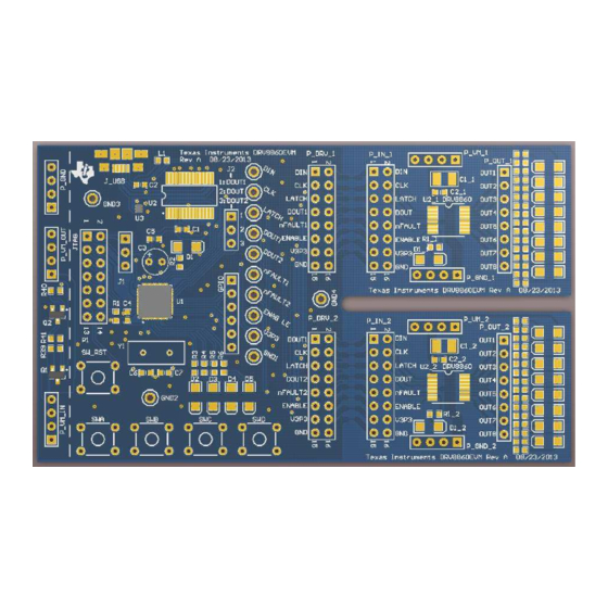
Page 2: Evm Hardware
EVM Hardware PCB Overview The EVM is 60 mm × 101 mm, The DRV8860 sub-module is 28 mm × 41 mm after separation. Refer to the following views of the top and bottom of the circuit board. Figure 2. Top View DRV8860 Customer Evaluation Module SLVU976 –... -
Page 3: Evm Connections
Power Connection TI recommends a lab power supply within the 8-V to 38-V range and a 2-A current limit function for the evaluation process. SLVU976 – September 2013 DRV8860 Customer Evaluation Module Submit Documentation Feedback Copyright © 2013, Texas Instruments Incorporated... - Page 4 2.2.2 Optional VM Switch Connection DRV8860 has an on-chip open-load detect function. This function causes an additional 30-µA current consumption by each channel. An optional VM switch on the board shuts down the DRV8860 circuit from the power supply. P_GND...
- Page 5 27 kΩ from the output to the VM. During the output off state, the open-load detection circuit inside DRV8860 sinks 30 µA from the load path. Although the 30-µA current is low, it causes the LED to emit a dim light during the off state. A 27 kΩ bypass resistor clamps the voltage drop to < 1 V in 30-µA condition, so that the LED can be totally shut off because 1 V does not suffice to reach the light...
-
Page 6: Jumper
All test points (or pins) with the same label are physically connected and have the same net. GND, GND1, GND2, GND3, and GND4 have the same net GND. Figure 9. Test Points in the EVM DRV8860 Customer Evaluation Module SLVU976 – September 2013 Submit Documentation Feedback Copyright © 2013, Texas Instruments Incorporated... -
Page 7: Schematic
EVM Hardware www.ti.com Schematic For a more detailed schematic, refer to the schematic file in the EVM reference package. SLVU976 – September 2013 DRV8860 Customer Evaluation Module Submit Documentation Feedback Copyright © 2013, Texas Instruments Incorporated... - Page 8 GPIO ENABLE MMBT3904 ENAB LE V3P3 RESET CBUS0 CBUS1 V3P3 OSCI CBUS2 GND1 CBUS3 CBUS4 GND2 OSCO TEST GND3 GND4 Figure 10. Schematic DRV8860 Customer Evaluation Module SLVU976 – September 2013 Submit Documentation Feedback Copyright © 2013, Texas Instruments Incorporated...
-
Page 9: Bill Of Materials
U2_1, U2_2 (Supplied) 8 Channel Serial Interface Low-Side Driver Digi-Key 296-21884-1-ND IC ESD-PROT ARRAY 2CH 6-SON Digi-Key X1094-ND CRYSTAL 8.00 MHZ 20PF 49US SLVU976 – September 2013 DRV8860 Customer Evaluation Module Submit Documentation Feedback Copyright © 2013, Texas Instruments Incorporated... -
Page 10: Gui Installation And Operation
GUI Installation and Operation www.ti.com GUI Installation and Operation Before running the GUI and commands, be familiar with the EVM hardware and the DRV8860 device specifications and functions. The following steps explain the GUI installation and operation. Install the GUI Software To install the GUI software, double click setup.exe in the install package folder. - Page 11 1. Check the box of OUT1 to OUT8 as needed, then click SEND OUTPUT DATA. The output of DRV8860 changes the state accordingly. There is a HEX indicator below the check box that displays the output data in HEX format.
-
Page 12: Full-Step Sequence
OLD information detects when the output bit is in the OFF state. 4. The ENABLE OUTPUT check box controls the ENABLE pin of the two DRV8860 devices. If it is checked off, the ENABLE pin drives low. All outputs shut off even if the output register is on. -
Page 13: Start-Up Operation
SWC Pressed Toggle CLK: H D4: Light Toggle CLK: L D4: Dark SWD Pressed Toggle DIN: H D5: Light Toggle DIN: L D5: Dark SLVU976 – September 2013 DRV8860 Customer Evaluation Module Submit Documentation Feedback Copyright © 2013, Texas Instruments Incorporated... - Page 14 Any exceptions to this are strictly prohibited and unauthorized by Texas Instruments unless user has obtained appropriate experimental/development licenses from local regulatory authorities, which is responsibility of user including its acceptable authorization.
- Page 15 FCC Interference Statement for Class B EVM devices This equipment has been tested and found to comply with the limits for a Class B digital device, pursuant to part 15 of the FCC Rules. These limits are designed to provide reasonable protection against harmful interference in a residential installation. This equipment generates, uses and can radiate radio frequency energy and, if not installed and used in accordance with the instructions, may cause harmful interference to radio communications.
- Page 16 Also, please do not transfer this product, unless you give the same notice above to the transferee. Please note that if you could not follow the instructions above, you will be subject to penalties of Radio Law of Japan. Texas Instruments Japan Limited (address) 24-1, Nishi-Shinjuku 6 chome, Shinjuku-ku, Tokyo, Japan http://www.tij.co.jp...
- Page 17 FDA Class III or similar classification, then you must specifically notify TI of such intent and enter into a separate Assurance and Indemnity Agreement. Mailing Address: Texas Instruments, Post Office Box 655303, Dallas, Texas 75265 Copyright © 2013, Texas Instruments Incorporated...
- Page 18 IMPORTANT NOTICE Texas Instruments Incorporated and its subsidiaries (TI) reserve the right to make corrections, enhancements, improvements and other changes to its semiconductor products and services per JESD46, latest issue, and to discontinue any product or service per JESD48, latest issue.
Need help?
Do you have a question about the DRV8860 and is the answer not in the manual?
Questions and answers