
Subscribe to Our Youtube Channel
Related Manuals for AMS JetCis 130


Summary of Contents for AMS JetCis 130
- Page 1 User Guide UG000473 JetCis_130 User Guide EVK with NVIDIA Jetson v2-01 • 2020-Aug-10...
-
Page 2: Table Of Contents
Document Feedback JetCis_130 Content Guide Content Guide Introduction ........3 JetCis Viewer ..........14 Shutting Down the System......22 Kit Content ............ 3 Resolving Common Problems ..23 Ordering Information ........3 Getting Started ....... 4 Appendix ........24 Hardware Description ....5 Test Pads of the Sensor Board .... -
Page 3: Introduction
Document Feedback JetCis_130 Introduction Introduction This is a user guide about the JetCis_130 which is a platform to evaluate the Mira130 sensor. The kit is built on top of an NVIDIA Jetson developer kit. The purpose of this guide is not to explain the sensor functionality, nor will it replace the NVIDIA Jetson manual. -
Page 4: Getting Started
Document Feedback JetCis_130 Getting Started Getting Started First, check if all items listed in the previous chapter are in the box. Add the following additional items to get started: ● HDMI monitor ● USB keyboard ● USB mouse ● Power outlet ●... -
Page 5: Hardware Description
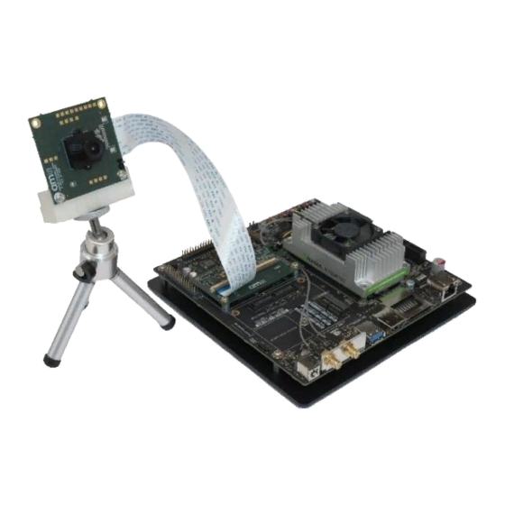
Document Feedback JetCis_130 Hardware Description Hardware Description The hardware contains as embedded computing platform an NVIDIA Jetson TX2 or NVIDIA Jetson Nano. Based on these two options, the hardware will vary slightly. This chapter describes the process of setting up the hardware. Hardware Architecture The difference between the two options is shown in the figure below. -
Page 6: Interposer Board (Tx2 Only)
Document Feedback JetCis_130 Hardware Description Mounting holes are present on the sensor board to connect a tripod mount to the tripod, see Figure 3. There is the possibility to extend the legs of the tripod. Besides those holes, there are also mounting holes for the lens holder to add a lens. - Page 7 Document Feedback JetCis_130 Hardware Description Connecting the interposer board with the sensor board: Open the connector on both boards carefully. Insert the end of the flat ribbon cable, with the exposed metal side facing down, into the slot between the connector clip and the base. Insert the cable straight and as far into the connector clip as it can go.
-
Page 8: Nvidia Jetson Tx2
Document Feedback JetCis_130 Hardware Description NVIDIA Jetson TX2 This section is applicable when the EVK consists of the NVIDIA Jetson TX2. All the hardware connectors are depicted in Figure 5. For more information, consult the NVIDIA Jetson TX2 manual. Figure 5: NVIDIA Jetson TX2 Revision B02/04 Connecting the interposer to the NVIDIA Jetson TX2: Plug in the interposer board connector in J22 on the NVIDIA Jetson TX2 as on Figure 6. - Page 9 Document Feedback JetCis_130 Hardware Description Figure 6: Connect Interposer Board with NVIDIA Jetson TX2 3.4.1 Connecting Other Hardware The EVK does not include a keyboard, mouse and display. The user can use his own hardware instead. The kit features a USB port and a mini USB port with an adapter. This way, two USB ports are available, which can be used for keyboard and mouse.
- Page 10 Document Feedback JetCis_130 Hardware Description Figure 7: Power LED (left); Power Button (right) Eval Kit Manual • PUBLIC UG000473 • v2-01 • 2020-Aug-10 │ 10...
-
Page 11: Nvidia Jetson Nano
Document Feedback JetCis_130 Hardware Description NVIDIA Jetson Nano 3.5.1 Schematic View Figure 8: Schematic Overview of the Jetson Nano Connections 3.5.2 Connecting the Hardware Connecting the Jetson Nano to the sensor board is done by opening the connectors both on the sensor board and on the Jetson Nano board. - Page 12 Document Feedback JetCis_130 Hardware Description Figure 9: Jetson Nano Connections 3.5.3 Powering Up the System The Jetson Nano does not have a power button. To power on the system, plug in the micro usb cable in the appropriate connector. The system will then boot up. Plug in the microUSB power supply Eval Kit Manual •...
-
Page 13: Software Description
Document Feedback JetCis_130 Software Description Software Description This chapter will explain how to use the graphical user interface of the EVK. Before proceeding to this step, check if the system is powered on, and the login screen appears. The Ubuntu Desktop After booting, a desktop will appear. -
Page 14: Jetcis Viewer
Document Feedback JetCis_130 Software Description 4.1.2 Configuring the Keyboard Layout In the status bar on the top right, next to the volume icon, the present keyboard layout is shown. By default, it is set to US QWERTY. 4.1.3 Connecting to a Network As shown in the figure below, the system will enable the Wi-Fi or wired connection chosen in the internet menu. - Page 15 Document Feedback JetCis_130 Software Description Hence, the application has root permission to modify the system. It can now change the driver to allow compatibility with different sensors and bit modes. A GUI shown in Figure 13 will appear. Figure 12: A Dialog Prompt for Credentials.
- Page 16 Document Feedback JetCis_130 Software Description Different bit modes such as 8-bit and 10-bit modes are available. Click open to load all the registers and GUI configurations. When the register upload is finished, a live image will appear. Figure 14: Select the Appropriate Configuration File Figure 15: Live Image Eval Kit Manual •...
- Page 17 Document Feedback JetCis_130 Software Description 4.2.3 GUI Features The GUI contains different features as seen in Figure 15. In this section, a detailed overview is given for each of the areas in the window. Menu Bar On top of the window, several actions can be selected by pressing the buttons in the menu bar. For some actions, a shortcut key exists.
- Page 18 Document Feedback JetCis_130 Software Description Widgets On the right of the window, widget are shown. This contains four tabs: ● Sync: set the signal for external triggering mode, see Figure 13 ● Status: sensor live information, see figure below ● ISP: image signal processing, see figure below ●...
- Page 19 Document Feedback JetCis_130 Software Description 4.2.4 Read/Write Registers with the GUI On the right side, it is possible to enter an address in the ‘Read’ section. Press GET to readout the value from the register. The output will be shown in the Status window at the bottom. To write a register, enter address and value in the appropriate fields.
- Page 20 Document Feedback JetCis_130 Software Description Figure 21: Add Python File to Configuration File In the created python file, you need to have at least the function controlInit() and controlSet(). Those are normally present because a file was copied. In controlInit(), change the name and other settings. The types where you can choose from are slider, list, checkbutton, text_entry_read, text_entry_write, checkbutton_and_slider and two_checkbuttons.
- Page 21 Document Feedback JetCis_130 Software Description Figure 22: Example Code of the Digital Gain Slider Eval Kit Manual • PUBLIC UG000473 • v2-01 • 2020-Aug-10 │ 21...
-
Page 22: Shutting Down The System
Document Feedback JetCis_130 Software Description Shutting Down the System Click the top right icon in the status bar, and click shutdown. The system will turn off. Now it is safe to plug or unplug the interposer/sensor boards. Figure 23: Shut Down Screen Eval Kit Manual •... -
Page 23: Resolving Common Problems
Document Feedback JetCis_130 Resolving Common Problems Resolving Common Problems This chapter explains how to resolve the most common issues. Figure 24: Common Issues Issue Solution/Suggestion Make sure the power supply is plugged in the wall socket and in the The system is not booting NVIDIA Jetson. -
Page 24: Appendix
Document Feedback JetCis_130 Appendix Appendix Test Pads of the Sensor Board On the PCB, there are several test pads provided. A detailed description of the test pads is given in the table below. Figure 25: Test Pads of Sensor Board Number Description Ground... -
Page 25: Test Pad Description Of The Interposer Board
Document Feedback JetCis_130 Appendix Number Description Internal reference voltage Sensor Internal reference voltage Sensor Internal reference voltage Sensor Internal reference voltage Sensor Sensor GPIO Sensor Sensor Ground Sensor MIPI data 0 negative Sensor MIPI data 0 positive Sensor MIPI data 1 negative Sensor MIPI data 1 positive Sensor... - Page 26 Document Feedback JetCis_130 Appendix Number Description Output power supply buffer gate Output power supply buffer gate Camera 0 I C device ID 0 Camera 0 PMIC GPIO Camera 0 I C device ID 1 Camera 0 DIN B- Camera 0 DIN B+ Camera 1 PMIC GPIO Camera 1 I C device ID 1...
-
Page 27: Revision Information
Document Feedback JetCis_130 Revision Information Revision Information Changes from previous version to current revision v2-01 Page Update folder structure according to new revision ● Page and figure numbers for the previous version may differ from page and figure numbers in the current revision. ●... -
Page 28: Legal Information
AG shall not be liable to recipient or any third party for any damages, including but not limited to personal injury, property damage, loss of profits, loss of use, interruption of business or indirect, special, incidental or consequential damages, of any kind, in connection with or arising out of the furnishing, performance or use of the technical data herein.
Need help?
Do you have a question about the JetCis 130 and is the answer not in the manual?
Questions and answers