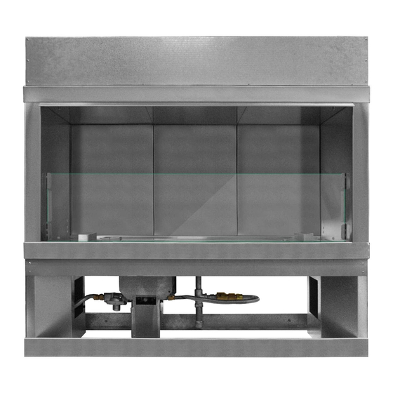
Firegear Kalea Bay OFP-36LECO-NLED Installation And Operating Instructions Manual
With led lighting, ecoflow + led
Hide thumbs
Also See for Kalea Bay OFP-36LECO-NLED:
- Installation and operating instructions manual (38 pages) ,
- Installation and operating instructions manual (44 pages) ,
- Installation and operating instructions manual (44 pages)
Table of Contents
Advertisement
Quick Links
KALEA BAY: E CO F LOW + LED
Installation and Operating Instructions
IF YOU CANNOT READ OR UNDERSTAND THESE INSTALLATION INSTRUCTIONS
DO NOT ATTEMPT TO INSTALL OR OPERATE THIS APPLIANCE
This fireplace requires a minimum 18-square inches (per side) of cross ventilation.
Failure to provide proper ventilation can void the warranty.
Kalea Bay Outdoor
Gas Fireplace with LED Lighting
LED MODEL
Natural Gas
OFP-36LECO-NLED
OFP-48LECO-NLED
OFP-60LECO-NLED
OFP-72LECO-NLED
INSTALLATION PRECAUTION:
Warning: For Outdoor Use Only
DO NOT DISCARD. THIS MANUAL
HAS IMPORTANT OPERATING AND
MANTENANCE INSTRUCTIONS.
LEAVE WITH THE HOMEOWNER.
MODEL:
SERIAL #:
MODELS
Description
36" Open Front Fireplace
48" Open Front Fireplace
60" Open Front Fireplace
72" Open Front Fireplace
16
MH# 60069
Advertisement
Table of Contents

Summary of Contents for Firegear Kalea Bay OFP-36LECO-NLED
- Page 1 KALEA BAY: E CO F LOW + LED DO NOT DISCARD. THIS MANUAL HAS IMPORTANT OPERATING AND MANTENANCE INSTRUCTIONS. LEAVE WITH THE HOMEOWNER. MODEL: SERIAL #: Kalea Bay Outdoor Gas Fireplace with LED Lighting Installation and Operating Instructions LED MODEL MH# 60069 MODELS Natural Gas...
-
Page 2: Specifications
K A LEA B AY: ECOFLOW + LED SPECIFICATIONS NOTE: These fireplaces come shipped as Natural Gas models only. There is an LP conversion kit available as an accessory. Ensure you order the specific conversion kit for your model fireplace. Table 1 shows the applicable information FRAMING FIREPLACE if converting to Liquid Propane (LP) gas. -
Page 3: End View
KALEA BAY: E CO F LOW + LED SINGLE-SIDED FIREPLACE DIMENSIONS & CLEARANCES Model: Natural Gas (NG) Overall Inside Overall Opening Overall Valve Clearance Clearance Length Opening Height Height Depth Height Depth Combustible Combustible Side Wall Ceiling OFP-36LECO-NLED 40” 36” 37½”... - Page 4 K A LEA B AY: ECOFLOW + LED SINGLE-SIDED FRAMING DIMENSIONS WITH METAL STUDS Model: Natural Gas (NG) Width Height Depth NOTE: This outdoor fireplace is not a “load bearing” fireplace. All finishing materials must be supported OFP-36LECO-NLED 40 ½” 37 ¾”...
- Page 5 KALEA BAY: E CO F LOW + LED SEE-THROUGH FIREPLACE DIMENSIONS & CLEARANCES ONLY This fireplace ships from the factory as a single sided fireplace, but by removing the back panels you can convert it into a see-through fireplace. Your specific application, single sided verses see-through, will determine your installation. Ensure you follow the proper clearances during installation.
- Page 6 K A LEA B AY: ECOFLOW + LED SEE-THROUGH FRAMING DIMENSIONS WITH METAL STUDS Model: Natural Gas (NG) Width Height Depth NOTE: This outdoor fireplace is not a “load bearing” OFP-36LECO-NLED 40 ½” 37 ¾” 15” fireplace. All finishing materials must be supported by the surrounding structure and not rely on the OFP-48LECO-NLED 52 ½”...
- Page 7 KALEA BAY: E CO F LOW + LED LED LIGHTING INSTALLATION This fireplace is equipped with LED lighting. Preparation for the LED lighting a must be planned before the fireplace finish materials are installed. After the fireplace is set in its final location the LED lighting will need to be installed and tested before finishing materials are applied.
- Page 8 K A LEA B AY: ECOFLOW + LED LED LIGHTING INSTALLATION Step 3: Locate the wire grommets inside the firebox. See Fig. 16. Directly above them will be a series of mounting holes for the windshield and LED retainer clips. Prepare the fireplace by installing the LED retainer clips. The retainer clips have two holes in them.
- Page 9 KALEA BAY: E CO F LOW + LED LED LIGHTING INSTALLATION Step 5: Remove the LED right channel assembly from the carton (The front of the channel has a shield facing the front with the LED wire hanging on the right side). See Figs. 19-21 for details. Note: If you are installing into a see-through fireplace you will install both right and left channels assemblies.
- Page 10 K A LEA B AY: ECOFLOW + LED LED LIGHTING INSTALLATION Step 7: Remove the screws from the “bottom end” of the burner pan area. The bottom end part fills the space between the burner pan and the fireplace side panel. It is held into place with three (3) screws.
- Page 11 KALEA BAY: E CO F LOW + LED LED LIGHTING INSTALLATION 5 / ” LED ON/OFF ON/OFF HI/LOW IPI/CONT PILOT LEARN 6 / ” ON/OFF LED ON/OFF HI/LOW IPI/CONT PILOT LEARN RGB DIMMER RGB DIMMER Fig. 24 RGB control box with 8 ¾” x 8 ¾” cover plate. Fig.
- Page 12 K A LEA B AY: ECOFLOW + LED LED LIGHTING INSTALLATION Kalea Bay LED Outdoor Fireplace REV. 4-17-19 Page 21...
- Page 13 KALEA BAY: E CO F LOW + LED LED WIRING DIAGRAM Kalea Bay LED Outdoor Fireplace REV. 4-17-19 Page 22...
- Page 14 K A LEA B AY: ECOFLOW + LED GAS VALVE WIRING DIAGRAM BATT Kalea Bay LED Outdoor Fireplace REV. 4-17-19 Page 23...
-
Page 15: Crushed Glass
Tube IMPORTANT: Media can only be placed in the trough and Use Firegear Outdoors large broken glass media (not burner pan area. No media is to be place into the shaded supplied). Table 8 will specify the proper amount needed. -
Page 16: Optional Accessories
K A LEA B AY: ECOFLOW + LED OPTIONAL ACCESSORIES The following accessories are available from your local Firegear dealer/distributor. Each accessory comes with a separate installation manual. Read each instruction thoroughly before installing. Firegear Outdoors Media LED See-Thru Conversion Kit...


