Table of Contents
Advertisement
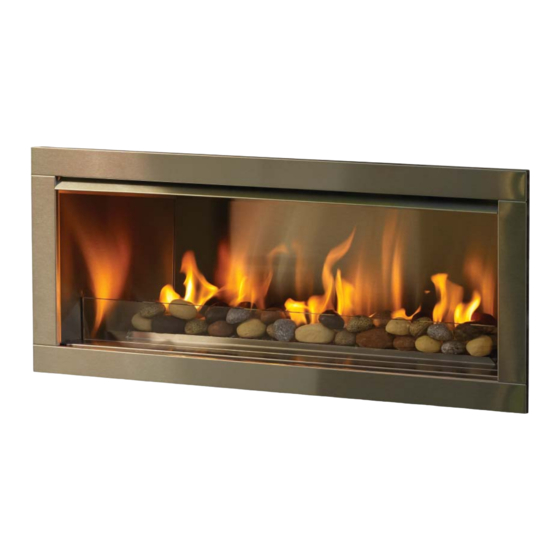
Night Fire Outdoor 42
WARNING:
If the information in these instructions are not followed exactly,
a fi re or explosion may result causing property damage,
personal injury or loss of life.
FOR YOUR SAFETY
Do not store or use gasoline or other fl ammable vapours and
liquids in the vicinity of this or any other appliance.
Installation and service must be performed by a qualifi ed
installer, service agency or the gas supplier.
WARNING:
Improper installation, adjustment, alteration, service or maintenance can cause injury or property
damage. Read the installation, operating and maintenance instructions thoroughly before installing
or servicing this equipment.
Tested by:
919-001a
Gas Fireplace
Installer: Please complete the details on the back cover
and leave this manual with the homeowner.
Homeowner: Please keep these instructions for future reference.
FIRE GEAR LLC, P.O. BOX 871250, CANTON, MI 48187
Installation Manual
MODELS: NFOD42-N
WARNING: FOR OUTDOOR USE ONLY
FOR YOUR SAFETY
What to do if you smell gas:
Do not try to light any appliance
Do not touch any electrical switch:
do not use any phone in your
building.
Immediately call your gas supplier
from a neighbour's phone. Follow
the gas supplier's instructions.
If you cannot reach your gas
supplier, call the fi re department.
Owners &
NFOD42-P
02/28/12
Advertisement
Table of Contents

Related Manuals for Firegear Nightfire NFOD42-N


Summary of Contents for Firegear Nightfire NFOD42-N
- Page 1 Owners & Night Fire Outdoor 42 Installation Manual Gas Fireplace MODELS: NFOD42-N NFOD42-P WARNING: FOR OUTDOOR USE ONLY WARNING: FOR YOUR SAFETY If the information in these instructions are not followed exactly, What to do if you smell gas: a fi re or explosion may result causing property damage, Do not try to light any appliance personal injury or loss of life.
- Page 2 To the New Owner: Congratulations! ® You are the owner of a state-of-the-art gas fi replace by fi regear . The Nightfi re™ NFOD42 Outdoor fi replace has been designed to provide you with all the warmth and charm of a fi re at the fl ick of a switch.
-
Page 3: Table Of Contents
TABLE OF CONTENTS SAFETY LABEL MAINTENANCE Maintenance Instructions..........32 Copy of Safety Decal .............4 Valve assembly Replacement ........33 Battery Replacement ...........34 DIMENSIONS PARTS Unit Dimensions ............5 Main Assembly ............36 INSTALLATION Burner Assembly ............37 Accessories ..............38 Important Message ............6 Before You Start ............6 General Safety Information..........6 WARRANTY Installation Checklist .............7... -
Page 4: Safety Label
APPAREIL FONCTIONNANT AU NATURAL GAS É QUIP A L'UISINE POUR GAZ PROPANE É 36” (914mm) PROPANE GAS: Model NFOD42-P NATURAL GAS: Model NFOD42-N CONCU POUR ETRE POELE: Mod le NFOD42 é CONCU POUR ETRE POELE: Mod le NFOD42 é Min. Mantel Height Maximum supply pressure 14”... -
Page 5: Dimensions
DIMENSIONS UNIT DIMENSIONS 37 - 13/16” (960mm) 41 - 11/16” (1059mm) 43 - 11/16” (1110mm) 15 - 3/16” (386mm) 39 - ½” (1003mm) 15 - 1/4” (387mm) 35 - 1/4” (895mm) 13 - 7/16” (341mm) 5/8” (16mm) NFOD42 Gas Fireplace... -
Page 6: Installation
INSTALLATION IMPORTANT MESSAGE 5) To prevent injury, do not allow anyone who is DO NOT USE THIS APPLIANCE IF unfamiliar with the operation to use the fi replace. SAVE THESE ANY PART HAS BEEN UNDER WATER. IMMEDIATELY CALL A QUALIFIED 6) Wear gloves and safety glasses for protection INSTRUCTIONS while doing required maintenance. -
Page 7: Installation Checklist
INSTALLATION LOCATING YOUR INSTALLATION GAS FIREPLACE CHECKLIST 1) When selecting a location for your fi replace, ensure that the clearances are met. 1) Locate appliance: 2) This appliance must be installed in an open-air situation with natural ventilation, without stagnant a) Refer to "Locating Your Gas fi... -
Page 8: Minimum Clearances To Combustibles
INSTALLATION MINIMUM CLEARANCES TO COMBUSTIBLES The clearances listed below are Minimum distances unless otherwise stated: A major cause of fi res is failure to maintain required clearances (air space) to combustible materials. It is of the greatest importance that this fi... -
Page 9: Framing Dimensions
INSTALLATION FRAMING DIMENSIONS Framing Description NFOD42 Dimensions Framing Height 32-11/16” (30mm) Framing Width 42 - 3/16" (1072mm) Framing Depth 14-5/8" (371mm) Minimum Height to Combustibles 34 - 1/4" (870mm) Corner Wall Depth 40 - 7/16" (1027mm) Corner Facing Wall Width 54 - 3/16"... -
Page 10: Mantel Clearances
INSTALLATION MANTEL CLEARANCES Due to the extreme heat this fi replace emits, the mantel clearances are critical. Combustible mantel clearances from 12" (305mm) top of front facing are shown in the diagram on the right. Combustible Material Note: Ensure the paint that is used on the mantel and the facing is "heat resistant"... -
Page 11: Finishing
INSTALLATION FINISHING IMPORTANT FINISHING DETAIL NOTE: Before placing unit into fi nal position - it is important to know the total thickness / height of fi nished hearth. The base of the fi replace should be level or higher than the fi nished hearth height. If material such as brick, stone, etc extends past the faceplate depth (1-1/2"), when fi... -
Page 12: High Elevation Gas Line Installation
INSTALLATION PILOT ADJUSTMENT 880 S.I.T. VALVE NFOD42-N SYSTEM DATA DESCRIPTION Max. Supply Pressure 14" WC (3.49 kpa) Periodically check the pilot fl ames. Correct fl ame Min. Supply Pressure 5" WC (1.25 kpa) pattern has two strong blue fl ames: 1 fl owing Manifold Pressure 3.5"... -
Page 13: Unit Assembly Prior To Installation
INSTALLATION UNIT ASSEMBLY PRIOR TO INSTALLATION NAILING STRIPS The 6 Standoffs must be correctly positioned and attached before unit is slid into position. The nailing strips come attached to the unit. There is 1 plate on each side and 1 on the top that can be folded out as required. Secure the top and side nailing strips to the framing. -
Page 14: Drain Installation (Recommended)
INSTALLATION DRAIN INSTALLATION (RECOMMENDED) Although this fi replace is designed to operate outdoors safely, rain and other sources of moisture may enter the hearth area, which will cause water to col- lect inside the base of the unit. To prevent excessive water collection, the installer must provide a way to drain the water from the base of the unit by building or installing a water collector before positioning the fi... -
Page 15: Wall Switch And Battery Installation
INSTALLATION WALL SWITCH AND BATTERY INSTALLATION (INCLUDED WITH UNIT) The unit comes with low voltage wire and a battery extension wire installed. 6) Install supplied 4-AA batteries into the battery holder. Using velcro install battery holder to the backside of the battery compartment door. Connect 1) Run supplied wire to desired location - to a max. -
Page 16: Wiring Diagram
INSTALLATION WIRING DIAGRAM This heater does not require a 120V A.C. supply for operation. (Do not cut the ground terminal off under any circumstances.) NOTE: 4 AA batteries must be installed in the battery pack to operate the burner switch. Profl... -
Page 17: Inner Panel Installation
INSTALLATION INNER PANEL INSTALLATION Before installation, panels must be handled and cleaned as per instructions noted below: Stainless Steel Panels • Stainless panels must be inspected for scratches and dimples prior to installation. All claims to be recorded at this time. Claims for damage after installation will not receive consideration. -
Page 18: Glass Crystal / Garden Stone Installation
INSTALLATION GLASS CRYSTAL / GARDEN STONE INSTALLATION Evenly spread the supplied Glass Crystals or optional Ceramic Spa or Garden Stones over the burner. Ensure the crystals (or stones) do not overlap too much as this will effect the fl ame pattern. IMPORTANT NOTE: Only the supplied approved Cobalt Glass, Ceramic Spa Stones or Garden Stones are to be used with these fi... -
Page 19: Pebble Installation
INSTALLATION PEBBLE INSTALLATION Firebox Packages Unit Glass Crystals Pebbles NFOD42 3 Bags 1 package (3 x bags pebbles) There are 3 optional packages to choose from to cover the fi rebox base: 1) White River Pebbles 2) Natural River Pebbles 3) Glass Crystals (4 colors available) Spread the pebbles / crystals evenly on the exposed base of the fi... -
Page 20: Optional Log Set Installation
INSTALLATION OPTIONAL LOG SET INSTALLATION Installation of Refl ective Panels must be completed before installing the log set. Read the instructions below carefully and refer to the images. If the logs are broken do not use the unit until they are replaced. Broken logs can interfere with pilot operation. - Page 21 INSTALLATION 4) Install log D on the burner as shown below. Orient log D across log E in the same way and in a similar position as depicted in Diagram 5- log D will rest up against the back panel. Diagram 5 5) Install log F on the right side of the burner as shown below.
-
Page 22: Heat Defl Ector Installation
INSTALLATION HEAT DEFLECTOR INSTALLATION 1) Install the heat defl ector to the top inside of the fi rebox with 4 screws as shown below. Heat Defl ector Heat Defl ector Installed NFOD42 Gas Fireplace... -
Page 23: Faceplate Installation
INSTALLATION FACEPLATE INSTALLATION Remove the protective coating from the faceplate before installation - see For installations where thicker fi nishing material is used - the optional handling instructions in panel install section. trim piece may be installed to fi ll the gap. Install the trim between the bottom access panel and the faceplate as To install the faceplate - line up the tabs on the faceplate with the 'C' shown below. -
Page 24: Glass Wind Shield Installation
INSTALLATION GLASS WIND SHIELD INSTALLATION 1) To install the glass wind shield - slot it into the space between the burner tray cover and the bottom access panel. Burner Tray Cover Glass Wind Shield Bottom Access panel WEATHER COVER INSTALLATION / REMOVAL 1) The unit should be covered when not in use for extended periods of time. - Page 25 INSTALLATION ASSEMBLY INSTRUCTIONS FOR A STEEL STUD FRAMING KIT FOR NFOD42 Follow these instructions to construct a steel stud frame for the Outdoor fi replace; Overall dimensions = 60" W x 20" D x 52-1/2" H. **Non-combustible fi nishing board not supplied with kit. Board may be purchased at your local hardware/building supply store. Tools Required 1 power drill...
- Page 26 INSTALLATION 1) Place top/bottom (A) on the ground - fl at side down. Bend 3) Line up the screw holes of (A) with (B). Secure the tabs up to a 90° angle. each (B) with 2 wafer screws (one on each side) as shown below.
- Page 27 INSTALLATION 6) Manoeuvre remaining (B) pieces and position in each corner 9) Position remaining 2 - (C) pieces offset from center rib as of the frame - fl at side facing out - see 2 diagrams below. shown below. 10) Position (D) on top of (C) pieces - line up screw holes and secure (D) to (C) with 12 wafer screws.
- Page 28 INSTALLATION 12) LIne up screw holes on (E) (header) and (B) (inner vertical 14) Line screw holes on 1 (F) (corner brace) with (B) + (A) and support). Secure with 2 wafer screws on each side (4 total) secure with 4 wafer screws. as shown below. as shown below.
- Page 29 INSTALLATION REMOTE PROPANE / LP GAS ENCLOSURES INSTALLATION GUIDELINES If the unit is permanently connected to a gas piping system • Bottom opening must provide a minimum of 1/2 from a remote supply tank, installation must be in accor- square inches (3.23 cm²) for each pound of pro- dance with local codes or, in absence of local codes, with the pane/LP contained in the tank (see example be- National fuel Gas codes ANSI Z223/1.NFPA 54.
-
Page 30: Operating Instructions
This condensation is normal and will disappear in a few minutes as Note: Aeration Adjustment should only be per- the glass heats up. formed by an authorized Firegear Installer at the time of installation or service. LIGHTING PROCEDURE 1) Turn on ON/OFF switch. -
Page 31: Copy Of Lighting Plate Instructions
OPERATING INSTRUCTIONS COPY OF LIGHTING PLATE INSTRUCTIONS The lighting plate is located on the underside of the front access panel in the unit. A) This appliance is equipped with an ignition device which automatically lights the pilot. FOR YOUR SAFETY READ BEFORE LIGHTING Do not try to light the pilot by hand. -
Page 32: Maintenance
Failure to do this will result in burn stains on panels which you will be unable to remove. ® 4) The heater is fi nished in a heat resistant paint and should only be refi nished with heat resistant paint. Firegear uses StoveBright Paint - Metallic Black #6309. -
Page 33: Valve Assembly Replacement
MAINTENANCE VALVE ASSEMBLY REPLACEMENT 1) Turn the unit off and allow it to cool down to room temperature. 9) Remove the front access panel by lifting up and out. 2) Turn off the gas supply to the unit. 3) Remove trim. 4) Remove the faceplate by lifting it up and off the unit. -
Page 34: Battery Replacement
MAINTENANCE 12) Slide the burner to the right and lift up and out of the fi rebox. 13) Remove the 5 screws securing the Digital Fireplace Burner Control to the fi rebox. 14) Remove the DFBC from the unit - see page 37. 15) Remove 6 screws an lift out valve tray. - Page 35 MAINTENANCE DIGITAL FIREPLACE BURNER CONTROL REMOVAL 1) To access to the Digital fi rebox burner control box - follow steps 1-11 from 5) Disconnect the yellow ground wire with green diagonal stripe for pilot the Valve assembly replacement instructions on pages 35,36. (CN2).
-
Page 36: Main Assembly
PARTS LIST Part # Description MAIN ASSEMBLY 326-054 Pilot Hood 1) 326-552 Faceplate Assembly 326-036 Top nailing strip 326-037/F Side nailing strip 2) 326-009 Heat Defl ector 326-074 Weather Cover 910-363 Wall Switch 5) 904-777 Orifi ce # 29 (NG) 919-001 Manual 904-434... -
Page 37: Burner Assembly
PARTS LIST BURNER ASSEMBLY Part # Description Part # Description 326-525 Burner Assembly NG 904-777 Orifi ce #29 NG 326-525 Burner Assembly LP 904-434 Orifi ce #47 LP 10) 911-024 Valve NG SIT 880 326-930 Log Set 911-025 Valve LP SIT 880 12) 911-006 Pilot Assembly - NG 911-007... -
Page 38: Accessories
PARTS LIST ACCESSORIES Part # Description 14) 940-368/P Glass windshield 15) 326-552 Faceplate Brushed Stainless 946-676 Copper Glass Crystals 946-695 Garden Stones NFOD42 Gas Fireplace... -
Page 39: Warranty
WARRANTY Fire Gear LLC products are designed with reliability and simplicity in mind. In addition, our internal Quality Assurance Team carefully inspects each unit thoroughly before it leaves our facility. Fire Gear LLC is pleased to extend this limited warranty to the original purchaser of a Fire Gear LLC Product. This warranty is not transferable. Limited Warranty: The combustion chamber is covered for parts and subsidized* labour only, against defect in manufacture only, for a period of (5) fi... - Page 40 WARRANTY fi regear fi replaces are designed with reliability and ® simplicity in mind. In addition, our internal Quality Assurance Team carefully inspects each unit thoroughly before it leaves our door. fi regear is pleased to extend this Limited Lifetime Warranty to the original purchaser of a fi...
Need help?
Do you have a question about the Nightfire NFOD42-N and is the answer not in the manual?
Questions and answers