Nordson Trilogy Product Manual
Manual electrostatic air spray/hvlp waterborne spray gun
Hide thumbs
Also See for Trilogy:
- Manual (22 pages) ,
- Customer product manual (21 pages) ,
- Manual (74 pages)
Table of Contents
Advertisement
Quick Links
Download this manual
See also:
Manual
Trilogyt Manual
Electrostatic Air Spray/HVLP
Waterborne Spray Gun
Customer Product Manual
Part 1093558A
Issued 6/09
For parts and technical support, call the Industrial Coating
Systems Customer Support Center at (800) 433-9319 or
contact your local Nordson representative.
This document is subject to change without notice.
Check http://emanuals.nordson.com for the latest version.
FM
C
US
APPROVED
NORDSON CORPORATION AMHERST, OHIO USA
Advertisement
Table of Contents
Troubleshooting

Related Manuals for Nordson Trilogy


Summary of Contents for Nordson Trilogy
- Page 1 For parts and technical support, call the Industrial Coating Systems Customer Support Center at (800) 433-9319 or contact your local Nordson representative. This document is subject to change without notice. Check http://emanuals.nordson.com for the latest version. APPROVED NORDSON CORPORATION AMHERST, OHIO USA...
- Page 2 MagnaLube is a registered trademark of General Magnaplate Corporation. Notice This is a Nordson Corporation publication which is protected by copyright. Perlast is a registered trademark of Precision Polymer Engineering Original copyright date 2009. No part of this document may be Limited.
- Page 3 ......Fluid Tip and Air Cap Installation ......Part 1093558A E 2009 Nordson Corporation...
- Page 4 ......... . . 7-14 Part 1093558A E 2009 Nordson Corporation...
- Page 5 ........Part 1093558A E 2009 Nordson Corporation...
- Page 6 Table of Contents Part 1093558A E 2009 Nordson Corporation...
-
Page 7: Safety
Regulations and Approvals Make sure all equipment is rated and approved for the environment in which it is used. Any approvals obtained for Nordson equipment will be voided if instructions for installation, operation, and service are not followed. Part 1093558A... -
Page 8: Personal Safety
To prevent injury, be aware of less-obvious dangers in the workplace that often cannot be completely eliminated, such as hot surfaces, sharp edges, energized electrical circuits, and moving parts that cannot be enclosed or otherwise guarded for practical reasons. Part 1093558A E 2009 Nordson Corporation... -
Page 9: High-Pressure Fluids
Part 1093558A E 2009 Nordson Corporation... -
Page 10: Fire Safety
Clean, maintain, test, and repair equipment according to the instructions in your equipment documentation. Use only replacement parts that are designed for use with original equipment. Contact your Nordson representative for parts information and advice. Halogenated Hydrocarbon Solvent Hazards Do not use halogenated hydrocarbon solvents in a pressurized system that contains aluminum components. -
Page 11: Action In The Event Of A Malfunction
Failure to observe this warning could result in an injection injury. WARNING: Risk of electrical shock. Disconnect and lockout input power to equipment before servicing. Failure to observe this warning may result in personal injury or death. Part 1093558A E 2009 Nordson Corporation... - Page 12 Safety Part 1093558A E 2009 Nordson Corporation...
-
Page 13: Description
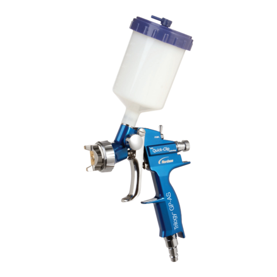
See Figure 2-1. The Trilogy manual electrostatic air spray/HVLP waterborne spray gun is designed to apply waterborne coating materials. It is used with the Nordson Iso-Flo system, which electrostatically charges waterborne coatings and delivers them to the spray gun while electrically isolating the charged coating from the coating supply. -
Page 14: Spray Gun Features
Description Spray Gun Features The Trilogy spray gun features: adjustable horn air pressure and fluid flow rate large air passages for higher air energy bellows-type packing cartridge 25 ft, in. ID fluid hose Spray Technology The fluid tip and air cap you choose to use determines the spray gun technology: air spray or HVLP. -
Page 15: Theory Of Operation
The packing cartridge (6) prevents fluid from flowing past it into the handle (15). The fluid flow is dead-ended at the spray gun when the trigger is released. Part 1093558A E 2009 Nordson Corporation... - Page 16 14. Horn air adjust knob 3. Retaining ring 9. Trigger 15. Handle 4. Extension 10. Trigger lock 16. Atomization air passage 5. Needle 11. Air inlet fitting 17. Horn air adjust valve 6. Packing cartridge 12. Handle cover Part 1093558A E 2009 Nordson Corporation...
-
Page 17: Air Flow
100 psi Maximum fluid input pressure 6.9 bar 100 psi Maximum fluid temperature 82 _C 180 _F NOTE: Supply air must be particulate free (5 microns maximum) and oil free. Use coalescing-type air filters. Part 1093558A E 2009 Nordson Corporation... -
Page 18: Electrostatics
Optional Air Hoses Length Fittings 9.14, 15.24, 30.48 meter 9.25 mm 1/4 in. NPS (30, 50, 100 ft.) (3/8 in.) female fittings Approvals This spray gun has met the requirements for FM and CE approval. Part 1093558A E 2009 Nordson Corporation... -
Page 19: Installation
WARNING: Risk of fire and/or electrical shock if the spray gun and system components are not properly grounded. make sure the system is properly grounded. NOTE: Inadequately grounded parts will adversely affect transfer efficiency and coating quality. Part 1093558A E 2009 Nordson Corporation... -
Page 20: Typical 60 Kv Waterborne System
3. Fluid supply line 8. Air line from air flow sensor 13. Air hose 4. System air regulator 9. Pressure switch 14. Spray gun 5. System air filter 10. Atomizing air pressure regulator 15. Electrostatic cable Part 1093558A E 2009 Nordson Corporation... -
Page 21: Air And Fluid Hose Connections
Do not walk on the hoses or run over them with heavy objects. If desired, cover the spray gun body, hoses, and other equipment in the spray area with a grounded, conductive wrapping to keep them clean. Part 1093558A E 2009 Nordson Corporation... -
Page 22: Fluid Tip And Air Cap Installation
Figure 3-2 Fluid Tip and Air Cap Installation 1. Needle 4. Air cap 2. Fluid tip O-ring 5. Retaining ring 3. Fluid tip Part 1093558A E 2009 Nordson Corporation... -
Page 23: Operation
WARNING: Do not add any joints or fittings to a waterborne fluid hose intended for use with spraying charged fluid. If the hose becomes damaged replace the entire hose assembly with the appropriate Nordson hose of identical length. WARNING: Ground all electrically conductive equipment. Ungrounded conductive equipment can store a static charge, which could ignite a fire or cause an explosion if a hot spark is discharged. -
Page 24: System Startup
Increase the air pressure to the switch. 9. Adjust the fluid pressure to obtain the desired atomization and spray pattern. Refer to Spray Pattern and Atomization Adjustments on page 4-3. Part 1093558A E 2009 Nordson Corporation... -
Page 25: Spray Adjustments
3. Adjust the horn air pressure to achieve the desired spray pattern. A higher pressure generates a wider and flatter fan pattern. Lowering the pressure decreases the pattern width and creates a rounder pattern. Part 1093558A E 2009 Nordson Corporation... -
Page 26: Fluid Tips And Air Caps
A range of airspray and HVLP fluid tips and air caps are available. Refer to the Trilogy HVLP and Air Spray Fluid Tip and Aircap Selection Charts included with this manual for part numbers. -
Page 27: Short-Term Shutdown
Packing Cartridge Replacement in the Repair section. You must remove the trigger and extension to check and adjust the needle travel. Slide calipers are required to check the adjustment. Part 1093558A E 2009 Nordson Corporation... -
Page 28: Hvlp Performance Testing
Kits must be ordered separately for each type of air cap. Refer to the Trilogy HVLP and Air Spray Fluid Tip and Aircap Selection Charts included with this manual for part numbers. NOTE: The 0.69 bar (10 psi) limit is for reference only. Many coating materials can be atomized using less pressure. - Page 29 9. If atomization quality is unacceptable, install the next size larger air cap or increase the air pressure above the optimum level. Figure 4-1 Using the HVLP Compliance Kit 1. Retaining ring 3. Horn air gauge 2. Atomization air gauge 4. Compliance air cap Part 1093558A E 2009 Nordson Corporation...
- Page 30 Operation Part 1093558A E 2009 Nordson Corporation...
-
Page 31: Maintenance
CAUTION: Trigger the spray gun to pull the needle out of the seat before removing the fluid tip. This will prevent damage to the needle and the seat. 6. Remove the air cap and fluid tip. Part 1093558A E 2009 Nordson Corporation... -
Page 32: Periodically
Maintenance Daily (contd) CAUTION: Use only a Nordson cleaning brush to clean the fluid tip and air cap. Using metal tools will damage the fluid tip and air cap causing faulty spray patterns. CAUTION: Avoid cleaning the spray gun with a pressurized cleaning solution. -
Page 33: System Flushing
7. Turn off the cleaning solution supply and relieve the pressure. Disconnect the fluid hose(s). Spray Gun Cleaning CAUTION: Use only a Nordson cleaning brush to clean the fluid tip and air cap. Using metal tools will damage the fluid tip and air cap causing faulty spray patterns. -
Page 34: Extensive Cleaning
Remove all seals before soaking any parts in cleaning solution. NOTE: Allow parts that have been soaked or heavily washed in solution to dry thoroughly (overnight) before assembling and reusing the spray gun. Part 1093558A E 2009 Nordson Corporation... -
Page 35: Troubleshooting
These procedures cover only the most common problems that you may encounter. If you cannot solve the problem with the information given here, contact your local Nordson representative for help. This section contains troubleshooting procedures for common spray gun problems. -
Page 36: Common Problems
Fluid too viscous Lower the viscosity by adding solvent or increasing the fluid temperature. Damaged fluid tip or air cap Inspect the fluid tip and air cap; replace them if they are damaged. Continued... Part 1093558A E 2009 Nordson Corporation... - Page 37 Use slower evaporating solvent. Contact your material supplier. 11. Coating material is Spray gun needs to be cleaned Clean the spray gun. Refer to Spray wrapping back onto Gun Cleaning on page 5-3. Use a gun cover. Part 1093558A E 2009 Nordson Corporation...
-
Page 38: Spray Pattern/Film Build Troubleshooting
Spray gun too far from the Move the spray gun closer to the substrate substrate. Horn air pressure too low Increase the horn air pressure. Fluid viscosity incorrect Change the fluid viscosity. Continued... Part 1093558A E 2009 Nordson Corporation... -
Page 39: Electrostatic Troubleshooting
Leaking packing cartridge Check the packing cartridge for leaks. Clean the packing cartridge bore and install a new packing cartridge and dielectric grease. Supply system Supply system grounding out Check the supply system. malfunction Part 1093558A E 2009 Nordson Corporation... - Page 40 Troubleshooting Part 1093558A E 2009 Nordson Corporation...
-
Page 41: Repair
Failure to observe this warning could result in injection injury. WARNING: Use only Nordson replacement parts to repair the spray gun. Deviating from the repair instructions, using unauthorized parts, or making unathorized modifications can result in personal injury or death and/or the loss of approvals by agencies such as Factory Mutual Research Corporation (FM). -
Page 42: Tools/Supplies Required
Removeable threadlocking adhesive (Loctite 242 or equivalent) Dielectric grease PTFE-based O-ring grease (MagnaLube-G or equivalent) Pipe/thread/hydraulic sealant/adhesive NOTE: Refer to the Parts section for service kits and individual part numbers. Figure 7-1 Combination Tool A. Screwdriver B. Fluid tip tool Part 1093558A E 2009 Nordson Corporation... -
Page 43: Air Cap, Fluid Tip, And Needle Replacement
Figure 7-2 Air Cap, Fluid Tip, and Needle Replacement 1. Retaining ring 4. Extension A. Air cap 2. Needle 5. Packing cartridge B. Fluid tip C. Fluid tip O-ring Part 1093558A E 2009 Nordson Corporation... -
Page 44: Trigger Lock Replacement
4. Disconnect the fluid and air hoses from the spray gun. Move the spray gun to a clean, dry, flat surface. Part 1093558A E 2009 Nordson Corporation... -
Page 45: Packing Cartridge Replacement
3. Screws (4) 11. Large O-ring 36. Trigger 4. Extension 12. Small O-rings (2) 37. Pivot screws (2) 9. Trigger puller 13. Handle 40. Fluid hose 10. Trigger spring 30. Hose bracket 41. Screws (2) Part 1093558A E 2009 Nordson Corporation... -
Page 46: Removing The Packing Cartridge
For thorough cleaning, remove the fluid tube from the extension. Figure 7-6 Packing Cartridge Replacement − Removing Cartridge From Extension and Pull Shaft 5. Packing cartridge 7. Pull shaft 8. Packing cartridge retainer 6. Sleeve Part 1093558A E 2009 Nordson Corporation... -
Page 47: Needle Travel Adjustment
Part 1093558A E 2009 Nordson Corporation... -
Page 48: Extension Installation
8. Turn on the fluid delivery system and make sure the spray gun is working correctly. Adjust fluid flow rate and atomization as desired. Refer to Fluid Pressure and Flow Rate Adjustments on page 4-3 and Spray Pattern and Atomization Adjustments on page 4-3. Part 1093558A E 2009 Nordson Corporation... -
Page 49: Air Valve Repair
NOTE: If there is no damage to the air valve stem, and air does not leak from the stem bore when the trigger is pulled, you should not have to replace the U-cup seal. Part 1093558A E 2009 Nordson Corporation... - Page 50 Remove the air valve stem. Use the blunt end of a dowel with a larger diameter than the inside diameter of the U-cup seal to press the seal into the recess. Make sure the end of the dowel does not have sharp edges. Part 1093558A E 2009 Nordson Corporation...
-
Page 51: Cover Installation
Lubricate the O-rings with MagnaLube-G or equivalent grease before re-installing the horn air valve. 4. Screw the horn air valve into the handle, then remove the knob. 5. Install the cover as described on page 7-11. Part 1093558A E 2009 Nordson Corporation... -
Page 52: Fluid Hose Replacement
11. Turn on the fluid-delivery system at a low pressure and slowly increase the fluid pressure to 6.89 bar (100 psi). If the hose fittings leak, retighten the fittings. Do not operate the system with leaking fittings. Part 1093558A E 2009 Nordson Corporation... - Page 53 7-13 Repair Large Ferrule Small Ferrule (43) Hose Nut (42) Hose (40) Figure 7-9 Multiplier Replacement 4. Extension 40. Fluid hose 42. Hose nut 30. Cable bracket 41. Screws (2) 43. Ferrule set Part 1093558A E 2009 Nordson Corporation...
-
Page 54: Service Notes
7-14 Repair Service Notes Refer to the Service Notes on page 7-15. Figure 7-10 Spray Gun Service Notes Part 1093558A E 2009 Nordson Corporation... - Page 55 Apply Loctite Prism 406 instant adhesive to outside small diameter of plug before installing. When installing a new ferrule set, tighten the hose nut 1- turns past hand-tight. If ferrule set has already been swaged, tighten the hose nut turn past hand-tight. Part 1093558A E 2009 Nordson Corporation...
- Page 56 7-16 Repair Part 1093558A E 2009 Nordson Corporation...
-
Page 57: Parts
Parts Section 8 Parts Introduction To order parts, call the Nordson Finishing Customer Support Center at (800) 433-9319 or contact your local Nordson representative. Use the illustrations and parts lists to locate and describe parts correctly. Spray Gun Parts NOTE: Before ordering parts for your spray gun, review the procedures in the Repair section to make sure you have the correct parts and service items to complete the procedure. - Page 58 S SCREW, pivot, trigger/handle 336353 S SPRING, compression, fluid adjustment 1093570 S SCREW, adjustment, #6−32, Trilogy 1094727 S KIT, hose, Trilogy, low pressure, manual, 25 ft 346725 S S MACH SCREW, flat, #4−40, 0.25 in. SS 1089413 S S NUT, hose, -in.
- Page 59 Parts Figure 8-1 Spray Gun Parts Part 1093558A E 2009 Nordson Corporation...
-
Page 60: Repair Kits
S PIN, dowel, 0.094 x 0.438 in., alloy steel Ferrule Kit Item Part Description Quantity Note − 1094775 KIT, ferrule, in., low pressure 1089413 S S NUT, hose, 1090625 S S FERRULE, set, 0.375 ID Part 1093558A E 2009 Nordson Corporation... -
Page 61: Recommended Spare Parts
AIR CAP 1094025 POSTER, Parts, manual, solventborne, Trilogy NOTE A: Refer to the Trilogy HVLP and Airspray Fluid Tip and Air Cap Selection Charts included with this manual for available part numbers and descriptions. Options Air Caps and Fluid Tips... -
Page 62: Cable Extension
971620 S S CONNECTOR, barbed, #3-56 x in., brass NOTE A: Refer to the Trilogy HVLP Fluid Tip and Air Cap Selection Chart included with this manual for kit and air cap part numbers. Figure 8-3 HVLP Compliance Kit Parts... - Page 63 They are supplied by HD ISO-FLO (voltage block system) and EPS6 manual controller (associated apparatus). The HD ISO-FLO system and EPS6 manual controller are installed in a safe area. The category 2 G of the TRILOGY manual applicator is strictly related to the use of waterborne paints only.
- Page 64 4. SAFETY INSTRUCTIONS FOR THE INSTALLATION IN HAZARDOUS AREA TRILOGY liquid applicator shall be installed & maintained according to the applicable standards regarding electrical installations in hazardous area. Before the installation READ CAREFULLY the INSTRUCTION MANUAL of the TRILOGY liquid applicator and the associated apparatus HD Manual ISO-FLO and EPS6.
- Page 65 Headquarters in Westlake Ohio, USA declare under our sole responsibility that the products TRILOGY Liquid Applicators including Air Spray / KVLP Models used with HD Manual ISO-FLO and EPS6. FOR USE WITH WATERBORNE PAINTS ONLY. to which this declaration relates complies with the following Directives:...
Need help?
Do you have a question about the Trilogy and is the answer not in the manual?
Questions and answers