Nordson Trilogy Manual
Electrostatic air spray/hvlp solventborne spray gun
Hide thumbs
Also See for Trilogy:
- Manual (22 pages) ,
- Product manual (67 pages) ,
- Customer product manual (21 pages)
Table of Contents
Advertisement
Quick Links
Trilogyt Manual
Electrostatic Air Spray/HVLP
Solventborne Spray Gun
Customer Product Manual
Part 1093591-02
Issued 6/19
For parts and technical support, call the Industrial Coating
Systems Customer Support Center at (800) 433-9319 or
contact your local Nordson representative.
This document is subject to change without notice.
Check http://emanuals.nordson.com for the latest version.
FM
C
US
APPROVED
NORDSON CORPORATION • AMHERST, OHIO • USA
Advertisement
Table of Contents
Troubleshooting

Related Manuals for Nordson Trilogy


Summary of Contents for Nordson Trilogy
- Page 1 For parts and technical support, call the Industrial Coating Systems Customer Support Center at (800) 433-9319 or contact your local Nordson representative. This document is subject to change without notice. Check http://emanuals.nordson.com for the latest version. APPROVED NORDSON CORPORATION • AMHERST, OHIO • USA...
- Page 2 Contact Us Trademarks Nordson Corporation welcomes requests for information, comments, and Trilogy, Nordson and the Nordson logo are registered trademarks of inquiries about its products. General information about Nordson can be Nordson Corporation. found on the Internet using the following address: http://www.nordson.com.
-
Page 3: Table Of Contents
....... Fluid Tip and Air Cap Installation ......Part 1093591-02 E 2019 Nordson Corporation... - Page 4 ......... . . 7-18 Part 1093591-02 E 2019 Nordson Corporation...
- Page 5 ........Part 1093591-02 E 2019 Nordson Corporation...
- Page 6 Table of Contents Part 1093591-02 E 2019 Nordson Corporation...
-
Page 7: Safety
Regulations and Approvals Make sure all equipment is rated and approved for the environment in which it is used. Any approvals obtained for Nordson equipment will be voided if instructions for installation, operation, and service are not followed. Part 1093591-02... -
Page 8: Personal Safety
To prevent injury, be aware of less-obvious dangers in the workplace that often cannot be completely eliminated, such as hot surfaces, sharp edges, energized electrical circuits, and moving parts that cannot be enclosed or otherwise guarded for practical reasons. Part 1093591-02 E 2019 Nordson Corporation... -
Page 9: High-Pressure Fluids
Part 1093591-02 E 2019 Nordson Corporation... -
Page 10: Fire Safety
Clean, maintain, test, and repair equipment according to the instructions in your equipment documentation. Use only replacement parts that are designed for use with original equipment. Contact your Nordson representative for parts information and advice. Halogenated Hydrocarbon Solvent Hazards Do not use halogenated hydrocarbon solvents in a pressurized system that contains aluminum components. -
Page 11: Action In The Event Of A Malfunction
Failure to observe this warning could result in an injection injury. WARNING: Risk of electrical shock. Disconnect and lockout input power to equipment before servicing. Failure to observe this warning may result in personal injury or death. Part 1093591-02 E 2019 Nordson Corporation... - Page 12 Safety Part 1093591-02 E 2019 Nordson Corporation...
-
Page 13: Description
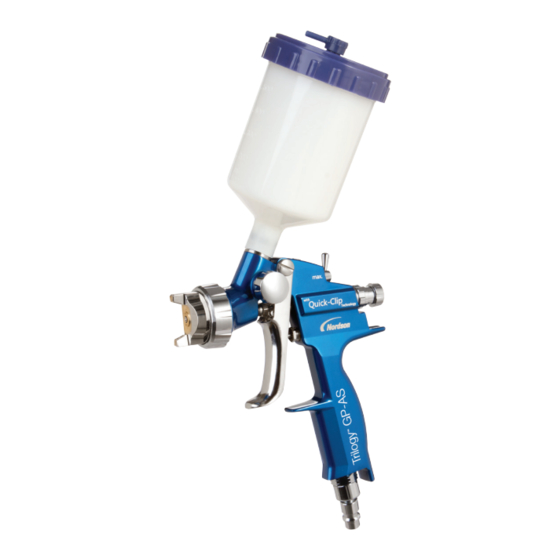
Description Introduction See Figure 2-1. The Trilogy manual electrostatic air spray/HVLP solventborne spray gun is designed for use with solventborne coating materials. It has an internal user-replaceable voltage multiplier that generates the high voltage used to electrostatically charge the coating materials as they are sprayed from the gun. -
Page 14: Spray Gun Features
Description Spray Gun Features The Trilogy spray gun features: adjustable horn air pressure and fluid flow rate large air passages for higher air energy user-replaceable voltage multiplier bellows-type packing cartridge Spray Technology The fluid tip and air cap you choose to use determines the spray gun technology: air spray or HVLP. -
Page 15: Theory Of Operation
The packing cartridge (14) prevents fluid from flowing past it into the handle. The fluid flow is dead-ended at the spray gun when the trigger is released. Part 1093591-02 E 2019 Nordson Corporation... - Page 16 17. Horn air valve 4. Extension 11. Trigger lock 18. Horn air adjust knob 5. Voltage LED 12. Trigger 19. Air cap 6. kV switch 13. Fluid control knob 20. Air valve 7. Handle 14. Packing cartridge Part 1093591-02 E 2019 Nordson Corporation...
-
Page 17: Air Flow
100 psi Maximum fluid input pressure 6.9 bar 100 psi Maximum fluid temperature 82 _C 180 _F NOTE: Supply air must be particulate free (5 microns maximum) and oil free. Use coalescing-type air filters. Part 1093591-02 E 2019 Nordson Corporation... -
Page 18: Electrostatics
-in. NPS, Male Optional Air Hoses Length Fittings 9.14, 15.24, 30.48 meter 9.25 mm 1/4 in. NPS (30, 50, 100 ft.) (3/8 in.) female fittings Approvals This spray gun has met the requirements for FM approval. Part 1093591-02 E 2019 Nordson Corporation... -
Page 19: Installation
WARNING: Risk of fire and/or electrical shock if the spray gun and system components are not properly grounded. make sure the system is properly grounded. NOTE: Inadequately grounded parts will adversely affect transfer efficiency and coating quality. Part 1093591-02 E 2019 Nordson Corporation... -
Page 20: Typical Air Spray And Hvlp System
3. Fluid heater 9. Fluid supply 15. Gun cable 4. Pump 10. Drain vavle 16. Air hose 5. Air lubricator 11. Siphon rod 17. Fluid hose 6. Air regulator 12. Siphon screen 18. Fluid pressure regulator Part 1093591-02 E 2019 Nordson Corporation... -
Page 21: Air And Fluid Hose Connections
1. Clean the fluid hose or fluid tube fittings with a clean, dry cloth. 2. Connect the fluid hose(s) between the fluid-delivery system outlet and in. NPSM straight fitting at the spray gun handle. Part 1093591-02 E 2019 Nordson Corporation... -
Page 22: Gun Cable Connection
250VAC F2 2A 250VAC POWER OUTPUT INPUT WARNING Separate only in a Non−Hazardous Area Figure 3-3 Gun Cable Connection 1. GUN OUTPUT receptacle 3. Gun cable plug 2. Air OUT fitting ( in. NPT) Part 1093591-02 E 2019 Nordson Corporation... -
Page 23: Securing Hoses And Cables
3. Pull the trigger to retract the needle (1). 4. Install the fluid tip over the needle and screw it into the extension with the combination tool. Tighten snugly but do not overtighten. Do not bend the electrode (2). Part 1093591-02 E 2019 Nordson Corporation... - Page 24 Figure 3-4 Fluid Tip and Air Cap Installation 1. Needle 4. Fluid tip O-ring 2. Electrode 5. Air cap 3. Fluid tip 6. Retaining ring Part 1093591-02 E 2019 Nordson Corporation...
-
Page 25: Operation
All conductive system components and flammable material containers are securely connected to a true earth ground. the operator station and spray area are clean and free of debris. Part 1093591-02 E 2019 Nordson Corporation... -
Page 26: System Startup
Refer to Spray Pattern and Atomization Adjustments on page 4-3. 10. Use a Nordson kV meter to read the maximum kV output of the voltage multiplier. Record the kV output for each new spray gun and use this information and the values from Electrostatic Troubleshooting in Section 6, Troubleshooting, as a baseline when troubleshooting. -
Page 27: Spray Adjustments
1. Set the supply air pressure to the control unit and spray gun. If using HVLP air caps and fluid tips, the air pressure should be set to 0.69 bar (10 psi) or less. Part 1093591-02 E 2019 Nordson Corporation... -
Page 28: Fluid Tips And Air Caps
A full range of airspray and HVLP fluid tips and air caps are available. Refer to the Trilogy Air Spray or HVLP Air Caps and Fluid Tips selection charts included with this manual. -
Page 29: Shutdown
CAUTION: Leaving the coating material in the spray gun longer than the indicated pot-life may clog the spray gun and require disassembly and replacement of major spray gun components. Refer to the coating material pot-life information to determine the proper shutdown procedures. Part 1093591-02 E 2019 Nordson Corporation... -
Page 30: Needle Travel Adjustment
HVLP compliance kit that consists of a modified air cap, air tubing, and pressure gauges. Kits must be ordered separately for each type of air cap. Refer to the Trilogy HVLP and Air Spray Fluid Tip and Aircap Selection Charts included with this manual for part numbers. - Page 31 9. If atomization quality is unacceptable, install the next size larger air cap or increase the air pressure above the optimum level. Figure 4-1 Using the HVLP Compliance Kit 1. Retaining ring 3. Horn air gauge 2. Atomization air gauge 4. Compliance air cap Part 1093591-02 E 2019 Nordson Corporation...
- Page 32 Operation Part 1093591-02 E 2019 Nordson Corporation...
-
Page 33: Maintenance
CAUTION: Trigger the spray gun to pull the needle out of the seat before removing the fluid tip. This will prevent damage to the needle and the seat. 6. Remove the air cap and fluid tip. Part 1093591-02 E 2019 Nordson Corporation... -
Page 34: Periodically
Cleaning with conductive solvents can result in loss of kV, carbon tracking, and permanent damage to spray gun components. CAUTION: Use only a Nordson cleaning brush to clean the fluid tip and air cap. Using metal tools will damage the fluid tip and air cap causing faulty spray patterns. -
Page 35: System Flushing
CAUTION: Do not clean the multiplier or gun cable with solvent. Failure to observe this caution could result in equipment damage. CAUTION: Use only a Nordson cleaning brush to clean the fluid tip and air cap. Using metal tools will damage the fluid tip and air cap causing faulty spray patterns. -
Page 36: Extensive Cleaning
(overnight) before assembling and reusing the spray gun. Electrostatic System Checks Use a Nordson non-loading kV meter to check the voltage multiplier output and a megohmmeter to check the spray gun resistances. The checks ensure that the operator, spray gun, and all conductive material within the spray area are connected to a true earth ground. -
Page 37: Troubleshooting
These procedures cover only the most common problems that you may encounter. If you cannot solve the problem with the information given here, contact your local Nordson representative for help. This section contains troubleshooting procedures for common spray gun problems;... -
Page 38: Common Problems
Fluid too viscous Lower the viscosity by adding solvent or increasing the fluid temperature. Damaged fluid tip or air cap Inspect the fluid tip and air cap; replace them if they are damaged. Continued... Part 1093591-02 E 2019 Nordson Corporation... - Page 39 Decrease the horn air pressure. 10. Coating material is Spray gun needs to be cleaned Clean the spray gun. Refer to Spray wrapping back onto Gun Cleaning on page 5-3. Use a gun cover. Part 1093591-02 E 2019 Nordson Corporation...
-
Page 40: Spray Pattern/Film Build Troubleshooting
Spray gun too close to substrate Move the spray gun farther from the substrate. Horn air pressure too low Increase the horn air pressure. Fluid too viscous Decrease the fluid viscosity. Continued... Part 1093591-02 E 2019 Nordson Corporation... - Page 41 Move the spray gun closer to the substrate substrate. Figure 6-1 Common Spray Pattern Faults 1. Blown pattern 4. Heavy left side 6. Heavy center 2. Heavy bottom 5. Heavy right side 7. Spitting 3. Heavy top Part 1093591-02 E 2019 Nordson Corporation...
-
Page 42: Electrostatic Troubleshooting
Tighten the fittings or replace is released the hose. Air valve seat worn or damaged Remove the air valve and inspect the sealing surface. Replace the air valve if worn or damaged. Part 1093591-02 E 2019 Nordson Corporation... -
Page 43: Multiplier And Needle Continuity And Resistance Check
(1) on the end of the multiplier. If the multiplier does not measure correctly, replace the multiplier. Refer to Multiplier Replacement in Section 6, Repair. Multiplier Check Common Resistor Check Figure 6-2 Multiplier and Needle Continuity and Resistance Check Part 1093591-02 E 2019 Nordson Corporation... -
Page 44: Gun Cable Continuity Check
Open Closed Closed Closed Open ⎯ Bracket Closed Trigger J1−1 Common J2−3 J1−2 +VDC J2−2 J1−3 uA Fdbk J2−1 J1−4 CABLE GROUND J1−5 Common J3−1 J3−2 J3−3 Switch Figure 6-3 Gun Cable Continuity Check Part 1093591-02 E 2019 Nordson Corporation... -
Page 45: Repair
Failure to observe this warning could result in injection injury. WARNING: Use only Nordson replacement parts to repair the spray gun. Deviating from the repair instructions, using unauthorized parts, or making unathorized modifications can result in personal injury or death and/or the loss of approvals by agencies such as Factory Mutual Research Corporation (FM). -
Page 46: Tools/Supplies Required
Removeable threadlocking adhesive (Loctite 242 or equivalent) Dielectric grease PTFE-based O-ring grease (MagnaLube-G or equivalent) Pipe/thread/hydraulic sealant/adhesive NOTE: Refer to the Parts section for service kits and individual part numbers. Figure 7-1 Combination Tool A. Screwdriver B. Fluid tip tool Part 1093591-02 E 2019 Nordson Corporation... -
Page 47: Air Cap, Fluid Tip, And Needle Replacement
NOTE: 991 and 992 air spray air caps are shipped permanently installed into retaining rings. Figure 7-2 Air Cap, Fluid Tip, and Needle Replacement 1. Retaining ring 5. Extension A. Air cap 2. Needle 6. Packing cartridge B. Fluid tip 3. Contact spring C. O-ring Part 1093591-02 E 2019 Nordson Corporation... -
Page 48: Trigger Lock Replacement
4. Disconnect the fluid and air hoses from the spray gun. Move the spray gun to a clean, dry, flat surface. Part 1093591-02 E 2019 Nordson Corporation... -
Page 49: Packing Cartridge Replacement
(10). Do not lose the one large and two small O-rings (16, 17, not shown) installed in the handle. 6. Remove the trigger spring (15) from the trigger puller (14) if it came out of the handle. Part 1093591-02 E 2019 Nordson Corporation... -
Page 50: Removing The Packing Cartridge
Removing the Packing Cartridge 1. See Figure 7-5. Hold the pull shaft (7) with pliers while unscrewing the trigger puller (14). Figure 7-5 Packing Cartridge Replacement − Removing Trigger Puller 7. Pull shaft 14. Trigger puller Part 1093591-02 E 2019 Nordson Corporation... -
Page 51: Packing Cartridge Installation
4. Coat the pull shaft, except for the threaded end, with a liberal amount of dielectric grease, then install the sleeve (8) over the pull shaft and up against the packing cartridge. 5. Apply a thin coating of dielectric grease to the outside of the sleeve. Part 1093591-02 E 2019 Nordson Corporation... -
Page 52: Needle Travel Adjustment
Figure 7-7 Packing Cartridge Replacement − Removing Trigger Puller 5. Install the extension as described in the following procedure. Part 1093591-02 E 2019 Nordson Corporation... -
Page 53: Extension Installation
10. Turn on the gun control unit and fluid delivery system and make sure the spray gun is working correctly. Adjust fluid flow rate and atomization as desired. Refer to Fluid Pressure and Flow Rate Adjustments on page 4-3 and Spray Pattern and Atomization Adjustments on page 4-3. Part 1093591-02 E 2019 Nordson Corporation... -
Page 54: Cable And Air Inlet Fitting Replacement
6. Secure the fitting (50) to the cable bracket with the two screws (51). 7. Install the horn air adjust knob (27) on the valve shaft, align the set screw (26) with the shaft flat, then tighten the set screw snugly. Part 1093591-02 E 2019 Nordson Corporation... - Page 55 37. Screws (2) 42. O-ring 25. Screws (3) 38. Lockwashers (2) 43. Screws (2) 26. Set screw 39. Switch actuator 50. Straight fitting 27. Horn air adjust knob 40A. Cable bracket 51. Screws (2) Part 1093591-02 E 2019 Nordson Corporation...
-
Page 56: Air Valve Repair
8. Lubricate the air valve plug O-ring (33) with MagnaLube-G or an equivalent lubricant and screw the air valve plug (32) into the handle until it is snug. 9. Install the cover as described on page 7-10. Part 1093591-02 E 2019 Nordson Corporation... - Page 57 21. Horn air valve 32. Plug 40A. Cable bracket 22. O-ring 33. O-ring 43. Screws (2) 25. Screws (3) 34. Spring 50. Straight fitting 26. Set screw 35. Air valve stem 51. Screws (2) Part 1093591-02 E 2019 Nordson Corporation...
-
Page 58: Horn Air Valve Repair
9. Snap the multiplier cable into the ribbed slots in the back of the handle. 10. Install the cover as described on page 7-10. 11. Connect the fluid and air hoses, then turn on the gun control unit and fluid delivery system and test gun operation. Part 1093591-02 E 2019 Nordson Corporation... - Page 59 40B. Cable connector 10B. Multiplier connector 26. Set Screw 43. Screws (2) 11. Heat sink bracket 27. Horn air adjust knob 50. Straight fitting 12. Screws (2) 31. Cover 51. Screws (2) 13. Screw 40. Cable Part 1093591-02 E 2019 Nordson Corporation...
-
Page 60: Fluid Tube Replacement
12. Turn on the fluid-delivery system at a low pressure and slowly increase the fluid pressure to 6.89 bar (100 psi). If the hose fittings leak, retighten the fittings. Do not operate the system with leaking fittings. Part 1093591-02 E 2019 Nordson Corporation... - Page 61 7-17 Repair Large Ferrule Small Ferrule Figure 7-11 Multiplier Replacement 5. Extension 51. Screws (2) 54. Hose nut 40A. Cable bracket 52. Ferrule nut 55. Ferrule set 50. Straight fitting 53. Fluid Tube Part 1093591-02 E 2019 Nordson Corporation...
-
Page 62: Service Notes
7-18 Repair Service Notes Figure 7-12 Spray Gun Service Notes Part 1093591-02 E 2019 Nordson Corporation... - Page 63 If replacing the switch pin, apply removeable threadlocking adhesive (Loctite 242) to the threads of the pin before installing. Apply a liberal amount of dielectric grease to the front 1/3 of the multiplier and contact spring before installing the multiplier into the handle and extension. Part 1093591-02 E 2019 Nordson Corporation...
- Page 64 7-20 Repair Part 1093591-02 E 2019 Nordson Corporation...
-
Page 65: Parts
Parts Section 8 Parts Introduction To order parts, call the Nordson Finishing Customer Support Center at (800) 433-9319 or contact your local Nordson representative. Use the illustrations and parts lists to locate and describe parts correctly. Spray Gun Parts NOTE: Before ordering parts for your spray gun, review the procedures in the Repair section to make sure you have the correct parts and service items to complete the procedure. - Page 66 S SCREW, pan, #2−56 x 0.375 in., steel, zinc 983113 S LOCK WASHER, split, 2, steel, zinc 132336 S ACTUATOR, switch 1095680 S CABLE, Trilogy, manual, 50 ft, 5 conductor 973505 S COUPLING, in., brass 940130 S O-RING, hotpaint, 0.438 x 0.563 x 0.063 in.
- Page 67 Parts Figure 8-1 Spray Gun Parts Part 1093591-02 E 2019 Nordson Corporation...
-
Page 68: Repair Kits
Needle Kit Item Part Description Quantity Note 1094722 KIT, needle, Trilogy − 1090577 S NEEDLE, potted, solvent 1090179 S SPRING, compression, contact, Trilogy Ferrule Kit Item Part Description Quantity Note − 1094775 KIT, ferrule, in., low pressure 1089413 S NUT, hose, -in. -
Page 69: Recommended Spare Parts
POSTER, parts, manual, solventborne, Trilogy NOTE A: Refer to the Trilogy Airspray Fluid Tip and Air Cap Selection Chart and the Trilogy HVLP Fluid Tip and Air Spray Selection Chart included with this manual for available part numbers and descriptions. -
Page 70: Cable Extension
971620 S S CONNECTOR, barbed, #3-56 x in., brass NOTE A: Refer to the Trilogy HVLP Fluid Tip and Air Cap Selection Chart included with this manual for kit and air cap part numbers. Figure 8-3 HVLP Compliance Kit Parts... - Page 71 0.070 336678 336678 O-Ring 1089638 0.080 Nozzle Conical fluid tip assembly 1089639 0.090 1089641 0.100 * These fluid tips are intended for use with Air Cap Trilogy waterborne guns only. 1610828-01 © 2019 Nordson Corporation All Rights Reserved Issued 08/19...
- Page 72 Trilogy Air Spray Fluid Tip and Air Cap ™ Selection Chart Refer to the appropriate Trilogy Spray Gun manual for other parts.
- Page 73 1094685 Heavy viscosity, high hi h Kits 1092137 solids, high flow 1089581 0.100 NOTE: Compliance kits include caps, gauges, and air tubing. Compliance kits are modified for testing ONLY. 1092138 TC-09-02 © 2009 Nordson Corporation All Rights Reserved Issued 4/09...
- Page 74 Trilogy HVLP Fluid Tip and Air Cap ™ Selection Chart Selection Chart Refer to the appropriate Trilogy Spray Gun manual for other parts. Refer to the appropriate Trilogy Spray Gun manual for other parts.
Need help?
Do you have a question about the Trilogy and is the answer not in the manual?
Questions and answers