Nordson kinetix Manual
Electrostatic airless spray gun
Hide thumbs
Also See for kinetix:
- Instruction sheet (7 pages) ,
- Customer product manual (74 pages) ,
- Customer product manual (77 pages)
Table of Contents
Advertisement
Quick Links
r
Kinetix
Electrostatic Spray Gun
Manual Airless
Customer Product Manual
Part 334598G03
Issued 8/08
For parts and technical support, call the
Finishing Customer Support Center at (800) 433-9319.
This document is subject to change without notice.
Check http://emanuals.nordson.com/finishing for the latest version.
FM
C
US
APPROVED
NORDSON CORPORATION AMHERST, OHIO USA
Advertisement
Table of Contents
Troubleshooting

Related Manuals for Nordson kinetix


Summary of Contents for Nordson kinetix
- Page 1 Part 334598G03 Issued 8/08 For parts and technical support, call the Finishing Customer Support Center at (800) 433-9319. This document is subject to change without notice. Check http://emanuals.nordson.com/finishing for the latest version. APPROVED NORDSON CORPORATION AMHERST, OHIO USA...
- Page 2 Viton is a registered trademark of E. I. DuPont de Nemours and Company. Notice This is a Nordson Corporation publication which is protected by copyright. Original copyright date 2000. No part of this document may be photocopied, reproduced, or translated to another language without the prior written consent of Nordson Corporation.
-
Page 3: Table Of Contents
..........Multi-Component Coatings ......Part 334598G03 E 2008 Nordson Corporation... - Page 4 Service Illustration and Notes ......7-18 Part 334598G03 E 2008 Nordson Corporation...
- Page 5 ......Kinetix Airless Manual Electrostatic Spray Gun ....
- Page 6 Table of Contents Part 334598G03 E 2008 Nordson Corporation...
-
Page 7: Safety
Regulations and Approvals Make sure all equipment is rated and approved for the environment in which it is used. Any approvals obtained for Nordson equipment will be voided if instructions for installation, operation, and service are not followed. Part 334598G03... -
Page 8: Personal Safety
If you suffer a fluid injection injury, seek medical care immediately. If possible, provide a copy of the MSDS for the injected fluid to the health care provider. Part 334598G03 E 2008 Nordson Corporation... -
Page 9: Fire Safety
Do not smoke, weld, grind, or use open flames where flammable materials are being used or stored. Do not heat materials to temperatures above those recommended by the manufacturer. Make sure heat monitoring and limiting devices are working properly. Part 334598G03 E 2008 Nordson Corporation... -
Page 10: Halogenated Hydrocarbon Solvent Hazards
Clean, maintain, test, and repair equipment according to the instructions in your equipment documentation. Use only replacement parts that are designed for use with original equipment. Contact your Nordson representative for parts information and advice. Halogenated Hydrocarbon Solvent Hazards Do not use halogenated hydrocarbon solvents in a pressurized system that contains aluminum components. -
Page 11: Safety Label
Failure to observe this warning could result in an injection injury. WARNING: Risk of electrical shock. Disconnect and lockout input power to equipment before servicing. Failure to observe this warning may result in personal injury or death. Part 334598G03 E 2008 Nordson Corporation... - Page 12 Safety Part 334598G03 E 2008 Nordson Corporation...
-
Page 13: Description
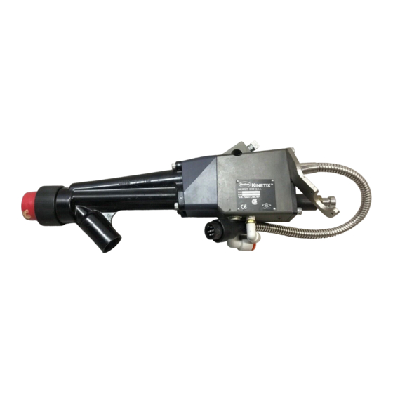
Section 2 Description Introduction See Figure 2-1. The Kinetix airless manual electrostatic high-pressure spray gun electrostatically charges and sprays liquid coatings. The spray gun is powered by a gun control unit and has a user-replaceable internal voltage multiplier. The spray gun is non-circulating and can be used with heated and unheated non-circulating spray systems. -
Page 14: Airless Description
NOTE: The seals in the spray gun are compatible with most coatings. If the coating material you use damages the seals, contact your Nordson Corporation representative for compatible replacements. Part 334598G03 E 2008 Nordson Corporation... -
Page 15: Theory Of Operation
Restrictors are pre-atomization devices that do not normally reduce flow, but aid in atomization and tend to reduce the pattern width. If a restrictor is used, the nozzle gasket is removed and replaced with a restrictor. Part 334598G03 E 2008 Nordson Corporation... - Page 16 11. Trigger lock 2. Fluid tip 7. Handle 12. Trigger 3. Multiplier 8. Electrostatic cable 13. Packing cartridge 4. Extension 9. Activation (trigger) air 14. Ball tip 5. LED voltage indicator 10. Fluid supply hose Part 334598G03 E 2008 Nordson Corporation...
-
Page 17: Installation
NOTE: A gasket or gasket with restrictor and the PTFE retaining washer are required. For assistance in selecting the appropriate nozzle and restrictor for your application, contact your Nordson Corporation representative. Before installation, make sure you have the appropriate nozzle, gasket or gasket with restrictor, electrode, and PTFE retaining washer for your application. -
Page 18: Typical Airless System
3. Heater (as required) 9. Fluid supply line 14. Control unit 4. Pump 10. Drain rod 15. Gun cable 5. Air lubricator 11. Drain valve 16. Air supply line (to spray gun) 6. Air regulator Part 334598G03 E 2008 Nordson Corporation... -
Page 19: Air And Fluid Hose Connections
Installation Air and Fluid Hose Connections Spray gun fittings accept standard Nordson hoses. Air Hose The air hoses supplying air to the spray gun should be no longer than 7.62 m (25 ft). Limit the number of restrictions in the air supply lines and hose to provide maximum air flow. - Page 20 Resistivity Range for Coatings Current Draw Through a One Foot Length of 0.25−in. ID Fluid Tube vs. Coating Resistivity Coating Resistivity (Megohms) Figure 3-3 Current Draw through a One Foot Length of 0.25-in. ID Fluid Tube Part 334598G03 E 2008 Nordson Corporation...
-
Page 21: Gun Cable
See Figure 3-4. Connect the gun cable (4) to the POWER OUTPUT or GUN OUTPUT receptacle (2) on the back of the gun control unit (1). Figure 3-4 Gun Cable Installation 1. Control unit 3. Cable connector 4. Gun cable 2. Cable receptacle Part 334598G03 E 2008 Nordson Corporation... -
Page 22: Securing The Hoses And Cables
2. Point the spray gun into the booth or waste container and activate the spray gun to relieve residual pressure. Lock the trigger to prevent inadvertent activation of the spray gun. Part 334598G03 E 2008 Nordson Corporation... - Page 23 NOTE: The cap screws into the retaining ring and rests in a groove in the ring that lets it rotate freely. Do not overtighten the cap. Part 334598G03 E 2008 Nordson Corporation...
- Page 24 Installation Part 334598G03 E 2008 Nordson Corporation...
-
Page 25: Operation
WARNING: The spray gun includes a trigger lock. Engage the trigger lock to prevent accidental triggering of the gun and possible injection injuries. Failure to observe this warning may result in injury. NOTE: Read this entire section before performing any procedures. Part 334598G03 E 2008 Nordson Corporation... -
Page 26: Daily Startup
4. Turn on the fluid heater(s), if used. Refer to your heater manual for operating instructions. Do not exceed 82 _C (180 _F). 5. Turn on the spray booth exhaust fans. 6. Check the fluid-delivery system for leaks. Part 334598G03 E 2008 Nordson Corporation... -
Page 27: Spray Pattern And Atomization Adjustments
Refer to Spray Pattern and Atomization Adjustments in this section. 8. Use a Nordson kV meter to read the kV output. Use this information and the values from Electrostatic Troubleshooting as a baseline when troubleshooting the electrostatic system. -
Page 28: Shutdown
CAUTION: Leaving the coating material in the spray gun longer than the indicated pot-life may clog the spray gun and require disassembly and replacement of major spray gun components. Refer to the coating material pot-life information to determine the proper shutdown procedures. Part 334598G03 E 2008 Nordson Corporation... -
Page 29: Maintenance
3. Turn off the gun control unit and ground the spray gun electrode to remove any residual charge. WARNING: Before changing nozzles or restrictors, shut down the system and relieve all fluid and air pressures. Failure to observe this warning could result in injury. Part 334598G03 E 2008 Nordson Corporation... - Page 30 Cleaning with conductive solvents can result in carbon tracking and loss of kV. CAUTION: Use only a Nordson cleaning brush to clean the fluid tip and cap. Using metal tools will damage the fluid tip and airless air cap, causing faulty spray patterns.
-
Page 31: Periodically
8. Inspect the air exhaust muffler to make sure that it is clean and permits the free flow of air. If air does not flow freely, remove the muffler and clean it with solvent. Part 334598G03 E 2008 Nordson Corporation... -
Page 32: Spray Gun Cleaning
Cleaning with conductive solvents can result in carbon tracking and loss of kV. CAUTION: Use only a Nordson cleaning brush to clean the fluid tip and cap. Using metal tools will damage the fluid tip and airless air cap, causing faulty spray patterns. -
Page 33: Extensive Cleaning
Remove all the seals before soaking any parts in solvent. Electrostatic System Checks Use a Nordson non-loading kV meter to perform checks on the electrostatic system, and a megohmmeter to check the resistance values on the spray gun. These checks ensure that the operator, electrostatic spray gun, electrostatic power supply, and all conductive material within the spray area are connected to a true earth ground. - Page 34 Maintenance Part 334598G03 E 2008 Nordson Corporation...
-
Page 35: Troubleshooting
These procedures cover only the most common problems that you may encounter. If you cannot solve the problem with the information given here, contact your local Nordson representative for help. This section contains troubleshooting procedures for common spray gun problems;... -
Page 36: Common Problems
Turn on the gun control unit. Excessive bounce Fluid pressures too high Reduce the fluid pressures. back Dry spray Spray gun held too far away from Move the spray gun closer to the substrate substrate. Part 334598G03 E 2008 Nordson Corporation... -
Page 37: Spray Pattern/Film Build Troubleshooting
Worn or damaged nozzle Replace the nozzle. Tails in pattern (3) Fluid pressure too low Increase the fluid pressure. Figure 6-1 Common Spray Pattern Faults 1. Fluttering or spitting 2. Irregular pattern 3. Tails in pattern Part 334598G03 E 2008 Nordson Corporation... -
Page 38: Electrostatic Troubleshooting
Continuity Check on page 6-6. Insufficient air flow to activate the Increase the air pressure. electrostatics Clogged or dirty muffler Clean or replace the muffler. Air pressure too low Increase the air pressure. Continued... Part 334598G03 E 2008 Nordson Corporation... -
Page 39: Multiplier Continuity And Resistance Check
120 V position. Refer to the Kinetix Manual Gun Power Supply manual for more information. Electrostatics will not Air leak in air hose Check the air hose and fittings for shut off when trigger leaks. -
Page 40: Gun Cable Continuity Check
NOTE: If the continuity check fails make sure the kV on/off switch is in the on position. Table 6-1 Spray Gun Cable Continuity Check Control Unit Connector Spray Gun Connector Position Open Closed Closed Closed Open Bracket Closed Figure 6-3 Gun Cable Continuity Check Part 334598G03 E 2008 Nordson Corporation... -
Page 41: Repair
Failure to observe this warning could result in injection injury. WARNING: Use only Nordson replacement parts to repair the spray gun. Deviating from the repair instructions, using unauthorized parts, or making unathorized modifications can result in personal injury or death and/or the loss of approvals by agencies such as Factory Mutual Research Corporation (FM) or the Canadian Standards Association (CSA). -
Page 42: Tools/Supplies Required
4. Disconnect the fluid hose from the spray gun. Move the spray gun to a clean, dry, flat surface. Part 334598G03 E 2008 Nordson Corporation... - Page 43 1. Retaining ring 5. Conductive ring B. Gasket or gasket with restrictor 2. Airless air cap 6. O-ring C. Electrode 3. Fluid tip 15. Ball tip D. PTFE retaining washer 4. Conductive back-up ring A. Nozzle Part 334598G03 E 2008 Nordson Corporation...
-
Page 44: Trigger Lock Replacement
NOTE: The cable will be secured in ribbed slots in the back of the spray gun’s handle. 4. Unscrew the old air inlet fitting (31) from the handle base and replace it with the new air inlet fitting. Tighten the fitting finger tight. Part 334598G03 E 2008 Nordson Corporation... - Page 45 8. Install the back cover using the three screws (41). Figure 7-4 Air Inlet Fitting Replacement 30. Screws A. Ground bracket 31. Air inlet fitting/male connector B. Cable connector 41. Screws C. Multiplier connector 45. Back cover D. Fluid hose fitting 52. Screws Part 334598G03 E 2008 Nordson Corporation...
-
Page 46: Ball Tip And Packing Cartridge Replacement
CAUTION: Do not overtighten threaded parts. Failure to observe this caution may result in equipment damage. The Kinetix spray gun is shipped with the standard gold packing cartridge. This durable packing cartridge is appropriate for most coating materials. Use the optional PTFE packing cartridge with harsh chemical solvents such as MEK. -
Page 47: Ball Tip And Packing Cartridge Removal
(23) with the combination tool. 3. Pull the puller out of the back of the extension to remove the puller, packing cartridge (18), and sleeve retainer (22). Do not bend the connecting wire (A). Part 334598G03 E 2008 Nordson Corporation... - Page 48 Screw the new ball tip into the ball tip fitting. Hand-tighten the ball tip until it is bottomed against the fitting. Wipe off excess adhesive. Part 334598G03 E 2008 Nordson Corporation...
-
Page 49: Ball Tip And Packing Cartridge Installation
(19) and the extension (7). 5. Secure the extension to the handle with the four socket-head screws (8). Tighten the screws to 1.36−1.58 Nm (12−14 in.-lb). Part 334598G03 E 2008 Nordson Corporation... -
Page 50: Air Valve Replacement
U-cup seal or stem bore. 3. Inspect the air valve stem (51). Replace the air valve stem if the elastomeric seat is damaged or the stem is worn or damaged. Part 334598G03 E 2008 Nordson Corporation... - Page 51 49. O-ring A. Ground bracket 36. U-cup seal 50. Spring B. Cable connector 41. Screws 51. Air valve stem C. Multiplier connector 45. Back cover 52. Screws D. Fluid hose fitting 48. Air valve plug Part 334598G03 E 2008 Nordson Corporation...
-
Page 52: Air Valve Installation
(B) from the multiplier connector (C). NOTE: The cable will be secured in ribbed slots in the back of the handle. 6. Remove the screws (13) securing the heat sink bracket (12) to the handle. Part 334598G03 E 2008 Nordson Corporation... - Page 53 10. Multiplier 19. Handle A. Ground bracket 11. Contact spring 30. Screws B. Cable connector 12. Heat sink bracket 41. Screws C. Multiplier connector 13. Screws 45. Back cover D. Dielectric grease 14. Screw Part 334598G03 E 2008 Nordson Corporation...
-
Page 54: Multiplier Installation
4. Slowly pull the back cover away from the handle and disconnect the cable connector (B) from the multiplierl connector (C). NOTE: The cable is secured in ribbed slots in the back of the handle. Part 334598G03 E 2008 Nordson Corporation... - Page 55 Gun Cable Replacement 30. Screws 35. Screws A. Ground Bracket 32. Electrostatic cable 41. Screws B. Cable connector 33. Actuator switch 45. Back cover C. Multiplier connector 34. Washers 52. Screws D. Fluid hose fitting Part 334598G03 E 2008 Nordson Corporation...
-
Page 56: Cable Installation
(A). Remove the fluid hose from the ground bracket. 4. Loosen the hose retaining nut (C) at the extension fluid inlet boss (D), and unscrew it completely. 5. Pull the hose assembly out of the extension. Part 334598G03 E 2008 Nordson Corporation... -
Page 57: Install The Fluid Hose
5. Screw the retaining nut (C) into the extension. Do not overtighten. 6. Install the fluid hose into the ground bracket (A). 7. Secure the fluid hose within the ground bracket with the two screws (52). Part 334598G03 E 2008 Nordson Corporation... -
Page 58: Service Illustration And Notes
7-18 Repair Service Illustration and Notes Use Figure 7-11 and Table 7-1 as a quick reference when repairing the spray gun. Figure 7-11 Spray Gun Service Notes Part 334598G03 E 2008 Nordson Corporation... - Page 59 Make sure the cable is snapped into the ribbed slots in the back of the handle. A removable threadlocking adhesive can be applied to the threads of the ball tip if there are problems with the ball tip backing out. Part 334598G03 E 2008 Nordson Corporation...
- Page 60 7-20 Repair Part 334598G03 E 2008 Nordson Corporation...
-
Page 61: Parts
A dash (—) is used when the part number applies to all parts in the illustration. The number in the Part column is the Nordson Corporation part number. A series of dashes in this column (- - - - - -) means the part cannot be ordered separately. -
Page 62: Kinetix Airless Manual Electrostatic Spray Gun
B: Included in Perlast fluid seal service kit 336679. Refer to Perlast Fluid Seal on page 8-6. C: Included in air seal service kit 336634. Refer to Air Seal on page 8-7. D: The optional ball tip kit 336637 may improve performance in some applications. Contact your Nordson representative for more information. - Page 63 Parts Figure 8-1 Kinetix Airless Manual Electrostatic Spray Gun Part 334598G03 E 2008 Nordson Corporation...
- Page 64 A-286 971265 S CONNECTOR, male, -in. tube x -in. NPT 336462 S CABLE, Kinetix, manual, 50 ft, 5 conductor 132336 S ACTUATOR SWITCH 983113 S LOCK WASHER, split, 2, steel, zinc 981915 S SCREW, pan head, #2−56 x 0.375 in., slotted,...
- Page 65 Parts Figure 8-1 Kinetix Airless Manual Electrostatic Spray Gun Part 334598G03 E 2008 Nordson Corporation...
-
Page 66: Adhesives, Sealants, And Lubricants
Item Part Description Quantity Note — 336679 FLUID SEAL KIT, Perlast, gun, Kinetix 336569 S BACKUP RING, conductive, 0.39-in. ID x 0.045-in. thick, cut 336678 S O-RING, Perlast, 0.375 x 0.50 x 0.063 in. 336677 S O-RING, Perlast, 0.25 x 0.375 x 0.063 in. -
Page 67: Air Seal
NOTE A: This O-ring is not used with this spray gun NS: Not Shown Packing Cartridge NOTE: The Kinetix spray gun is shipped with the gold packing cartridge, which is appropriate for most coating materials. Use the optional PTFE packing cartridge 1089862 with harsh chemical solvents such as MEK. -
Page 68: Optional Hotpaint Fluid Seal
Parts Optional Hotpaint Fluid Seal The standard fluid seal O-rings for all Kinetix products provide solvent resistance. If a particular application does not require solvent resistance then the hotpaint seal kit can be used instead. These O-rings should not be... -
Page 69: Recommended Spare Parts
NOTE A: Fluid seal kit 336679 is standard, fluid seal kit 336633 is optional. B: The Kinetix spray gun is shipped with the standard gold packing cartridge. This durable packing cartridge is appropriate for most coating materials. Use the optional PTFE packing cartridge with harsh chemical solvents such as MEK. - Page 70 8-10 Parts Part 334598G03 E 2008 Nordson Corporation...
-
Page 71: Specifications
NOTE: Supply air must be particulate free (5 microns maximum) and oil free. Use coalescing-type air filters. Standard Fitting Sizes Spray Gun Standard Fitting Sizes Activation (trigger) air -in. tube Fluid fitting -20 JIC, male Part 334598G03 E 2008 Nordson Corporation... -
Page 72: Gun Electrostatics
Conductivity Range For optimum electrostatics coating resistivity the conductivity range should be greater than 25 megohms/cm. Approvals This spray gun has met the requirements for CE and FM approval. Part 334598G03 E 2008 Nordson Corporation... - Page 73 Zone 2 4. SAFETY INSTRUCTIONS FOR THE INSTALLATION IN HAZARDOUS AREA KINETIX / TRILOGY liquid pistols shall be installed & maintained according to the applicable standards regarding electrical installations in hazardous area. Before the installation READ CAREFULLY the INSTRUCTION MANUAL of the KINETIX / TRILOGY liquid pistol and IPS20 controller or associated apparatus.
- Page 74 5. EXAMPLE OF APPLICATION This shows the applicators and how a typical system is configured. Safety Note KINETIX – TRILOGY / ATEX Page. 2 DOC13015B05...
- Page 75 Safety Note KINETIX – TRILOGY / ATEX Page. 3 DOC13015B05...
- Page 76 Headquarters in Westlake Ohio, USA declare under our sole responsibility that the products KINETIX High Pressure or TRILOGY Low Pressure Liquid Applicators including Air Spray / KVLP, Air Assisted Airless and Airless Models used with IPS-20 Manual Controllers. to which this declaration relates complies with the following Directives:...
Need help?
Do you have a question about the kinetix and is the answer not in the manual?
Questions and answers