Magnetek FLEX BASE Instruction Manual
Ir programmer
Hide thumbs
Also See for FLEX BASE:
- Quick reference manual (2 pages) ,
- Quick reference manual (2 pages) ,
- Operator's manual (23 pages)
Table of Contents
Advertisement
Advertisement
Table of Contents

Related Manuals for Magnetek FLEX BASE


Summary of Contents for Magnetek FLEX BASE
- Page 1 IR Programmer Instruction Manual V2.1 (February 2018)
-
Page 2: Table Of Contents
Flex EX Models Flex EX2 Models Flex 2JX Models Flex Mini Models Flex BASE Models Flex EP-H Models 10. TAC Programming 11. Firmware Update 12. Pushbutton Function Table A. Flex EX Models B. Flex EX2 Models C. Flex BASE Models Page 1... -
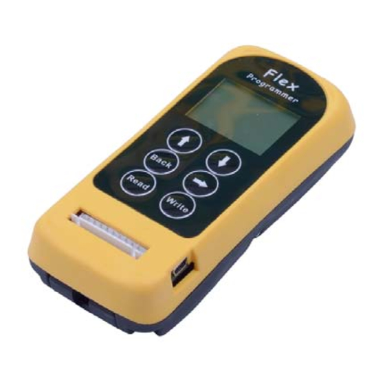
Page 3: External Illustrations
1. External Illustrations Infrared sensors “WRITE” button LCD screen Programming port ↑ “ ” button Mini USB Port (for firmware update) ↓ “ ” button I-Chip port “BACK” button I-Chip programming board connector → “ ” button Connector to programming port “READ”... -
Page 4: Power On/Off The Unit
2. Power On/Off the Unit 1) Nothing is shown on the LCD screen when power is off. Power off 2) Press the “→” button to power on the unit. Power off Power on > F L E X - E X F L E X - 2 J X Press “→”... -
Page 5: Flex Ex Models
4. Flex EX Models 4.1 Program I-Chip When entering the Flex EX model the first selection shown on the screen is “Program I-Chip”. Use the “↑” and “↓” buttons to scroll through various Flex EX settings or press “→” button to enter “Program I-Chip”. Make sure the I- Chip is connected to the programmer. - Page 6 8) Exit Program System Type by pressing the “BACK” button until the cursor is shown next to “TYPE:”. 9) Press “↑” and “↓” button to scroll through other Flex EX settings. When finished, take out the I-Chip and insert it onto the I-Chip programming port located on the decoder module to transfer the new system type from the I-Chip to the receiver.
- Page 7 8) Exit Program Transmitter Timer by pressing the “BACK” button until the cursor is shown next to “TX TIMER”. 9) Press “↑” and “↓” button to scroll through other Flex EX settings. 4.8 Program Password (TX) 1) Make sure the I-Chip is connected to the programmer.
- Page 8 3) Press “↑” and “↓” button to scroll and select. 4) Exit Program Function Relay by pressing the “BACK” button until the cursor is shown next to “FUNC RLY”. 5) Press “↑” and “↓” button to scroll through other Flex EX settings. START function only. NORMAL START function + AUX with normal momentary output.
- Page 9 8) Exit Program Serial Number by pressing the “BACK” button until the cursor is shown next to “TXSN”. 9) Press “↑” and “↓” button to scroll through other Flex EX settings. 4.13 Program Project ID (Flex Pro transmitter) 1) Make sure the I-Chip is connected to the programmer.
-
Page 10: Flex Ex2 Models
5. Flex EX2 Models 5.1 Program IR 5.1.1 Transmitter 1) Rotate the power switch key to OFF ( 0 ) position. 2) With the STOP button elevated, press and hold PB1 and PB3 at the same time. 3) Rotate the power switch key to ON ( I ) position. 4) Release PB1 and PB3 at the same time. - Page 11 5.2 Program Serial Number (TX & RX) 1) Press “→” button to enter Serial Number setting. 2) Press “↑” and “↓” button to change serial number as a whole or… 3) Press “→” button to go to the 1 digit on the far left of the serial number. 4) Press “↑”...
- Page 12 5.6 Program System Channel (TX & RX) 1) Press “→” button to enter System Channel setting. 2) Press “↑” and “↓” button to change system channel as a whole or… 3) Press “→” button to go to the digit on the left. 4) Press “↑”...
- Page 13 5.10 Program Transmitter Inactivity Timer (TX) 1) Press “→” button to enter Transmitting Timer setting. 2) Press “↑” and “↓” button to select “_M” for minutes/seconds or “ON” for constant on. 3) When “ON” is selected, press “→” button and then “↑” and “↓” button to select “+START”...
- Page 14 5.13 Program LED3 Feedback (TX) 1) Press “→” button to enter Feedback setting. 2) Press “↑” and “↓” button to select Off, Input number or Output number. 3) When “Input” is selected, press “→” button and then “↑” and “↓” button to select input number that the external source is connected to (IN1 ~ IN4).
- Page 15 5.17 Program IRS Time Out (TX) 1) Press “→” button to enter IRS Time Out setting. 2) Press “↑” and “↓” button to select IRS Off or IRS On. Select “IRS On” if infrared START is required after every transmitter timeout. Select “IRS Off”...
- Page 16 5.20 Program Function Relay 2 / K26 Relay (RX) 1) Press “→” button to enter Function Relay 2 setting. 2) Press “↑” and “↓” button to scroll and select. 3) Exit Program Function Relay 2 by pressing the “BACK” button until the cursor is shown next to “FUNC RLY2”.
- Page 17 5.22 Program Brake Functions (RX) 1) Press “→” button to enter Brake function setting. 2) Press “↑” and “↓” button to scroll and select. 3) Exit Program Brake Functions by pressing the “BACK” button until the cursor is shown next to “BRAKE”. 4) Press “↑”...
-
Page 18: Flex 2Jx Models
6. Flex 2JX Models 6.1 Program I-Chip When entering the 2JX model the first selection shown on the screen is “Program I-Chip” or “Program IR”. Use the “↑” and “↓” buttons to scroll through various Flex 2JX settings or press “→” button to enter “Program I- Chip”... - Page 19 6.2 Program Serial Number (TX & RX) 1) Make sure the I-Chip is connected to the programmer. 2) Press “→” button to enter Serial Number setting. 3) Press “↑” and “↓” button to change serial number as a whole or… 4) Press “→”...
- Page 20 6.6 Program Transmitter Inactivity Timer (TX) 1) Make sure the I-Chip is connected to the programmer. 2) Press “→” button to enter Transmitting Timer setting. 3) Press “↑” and “↓” button to select between “__M__S” and “ON”. “__M__S” represents Minutes and Seconds and “ON” represents constant ON. 4) When “__M__S”...
- Page 21 6.9 Program Infrared (IR) Identification Number (TX) 1) Make sure the I-Chip is connected to the programmer. 2) Press “→” button to enter Infrared ID setting. 3) Press “↑” and “↓” button to change IR_ID as a whole or… 4) Press “→” button to go to the digit on the far left. 5) Press “↑”...
- Page 22 6.12 Program LX Joystick Function (TX) 1) Make sure the I-Chip is connected to the programmer. 2) Press “→” button to enter LX Joystick setting. 3) Press “↑” and “↓” button to scroll and select between None, Analog, 1-step, 2-step, 3-step, 4-step and 5-step. 4) Exit Program LX Function by pressing the “BACK”...
- Page 23 6.16 Program SW1 Function (TX) 1) Make sure the I-Chip is connected to the programmer. 2) Press “→” button to enter SW1 setting. 3) Press “↑” and “↓” button to scroll and select between settings. 4) Exit Program SW1 Function by pressing the “BACK” button until the cursor is shown next to “SW1FUNC”.
- Page 24 6.19 Program SW4 Function (TX) 1) Make sure the I-Chip is connected to the programmer. 2) Press “→” button to enter SW4 setting. 3) Press “↑” and “↓” button to scroll and select between settings. 4) Exit Program SW4 Function by pressing the “BACK” button until the cursor is shown next to “SW4FUNC”.
- Page 25 6.22 Program SW7 Function (TX) 1) Make sure the I-Chip is connected to the programmer. 2) Press “→” button to enter SW7 setting. 3) Press “↑” and “↓” button to scroll and select between settings. 4) Exit Program SW7 Function by pressing the “BACK” button until the cursor is shown next to “SW7FUNC”.
- Page 26 6.25 Program Function Relay 1 (RX) 1) Make sure the I-Chip is connected to the programmer. 2) Press “→” button to enter Function Relay 1 setting. 3) Press “↑” and “↓” button to scroll and select between settings. 4) Exit Program Function Relay 1 by pressing the “BACK” button until the cursor is shown next to “FUNC RLY1”.
- Page 27 6.26 Program Function Relay 2 (RX) 1) Make sure the I-Chip is connected to the programmer. 2) Press “→” button to enter Function Relay 2 setting. 3) Press “↑” and “↓” button to scroll and select between settings. 4) Exit Program Function Relay 2 by pressing the “BACK” button until the cursor is shown next to “FUNC RLY2”.
- Page 28 6.27 Program LX Output Relay (RX) Below chart and settings are various types of shared (F/R) and separate (F or R) acceleration relay closure at 1 and 5 steps. Output Relay Type at 1 Step or R1 at 2 Step or R1 F/R2 at 3...
- Page 29 6.28 Program LY Output Relay (RX) Below chart and settings are various types of shared (F/R) and separate (F or R) acceleration relay closure at 1 and 5 steps. Output Relay Type at 1 Step or R1 at 2 Step or R1 F/R2 at 3...
- Page 30 6.29 Program RX Output Relay (RX) Below chart and settings are various types of shared (F/R) and separate (F or R) acceleration relay closure at 1 and 5 steps. Output Relay Type at 1 Step or R1 at 2 Step or R1 F/R2 at 3...
- Page 31 6.30 Program RY Output Relay (RX) Below chart and settings are various types of shared (F/R) and separate (F or R) acceleration relay closure at 1 and 5 steps. Output Relay Type at 1 Step or R1 at 2 Step or R1 F/R2 at 3...
- Page 32 6.31 Program LX Delay (RX) 1) Make sure the I-Chip is connected to the programmer. 2) Press “→” button to enter LX Delay setting. 3) Press “↑” and “↓” button to select delay for ACC (forward motion) and DEC (reverse motion). 4) Press “→”...
- Page 33 6.35 Program LX Output (RX) 1) Make sure the I-Chip is connected to the programmer. 2) Press “→” button to enter LX Output setting. 3) Press “↑” and “↓” button to scroll between OFF, Voltage, Current and PFM output setting. Press “→” button to enter. When Voltage is selected on step 3 above: press “↑”...
- Page 34 6.37 Program RX Output (RX) 1) Make sure the I-Chip is connected to the programmer. 2) Press “→” button to enter RX Output setting. 3) Press “↑” and “↓” button to scroll between OFF, Voltage, Current and PFM output setting. Press “→” button to enter. When Voltage is selected on step 3 above: press “↑”...
- Page 35 6.39 Program SW1 Output Relay (RX) 1) Make sure the I-Chip is connected to the programmer. 2) Press “→” button to enter SW1 Output Relay setting. 3) Press “→” button and then “↑” and “↓” button to select “LOCK” or “UNLOCK”. 4) Press “BACK”...
- Page 36 6.40 Program SW2 Output Relay (RX) 1) Make sure the I-Chip is connected to the programmer. 2) Press “→” button to enter SW2 Output Relay setting. 3) Press “→” button and then “↑” and “↓” button to select “LOCK” or “UNLOCK”. 4) Press “BACK”...
- Page 37 6.41 Program SW3 Output Relay (RX) 1) Make sure the I-Chip is connected to the programmer. 2) Press “→” button to enter SW3 Output Relay setting. 3) Press “→” button again to enter settings. 4) Press “↑” and “↓” button to scroll and select. 5) Exit Program SW3 Output Relay by pressing the “BACK”...
- Page 38 6.42 Program SW4 Output Relay (RX) 1) Make sure the I-Chip is connected to the programmer. 2) Press “→” button to enter SW4 Output Relay setting. 3) Press “→” button and then “↑” and “↓” button to select “LOCK” or “UNLOCK”. 4) Press “BACK”...
- Page 39 6.43 Program SW5 Output Relay (RX) 1) Make sure the I-Chip is connected to the programmer. 2) Press “→” button to enter SW5 Output Relay setting. 3) Press “→” button and then “↑” and “↓” button to select “LOCK” or “UNLOCK”. 4) Press “BACK”...
- Page 40 6.44 Program SW6 Output Relay (RX) 1) Make sure the I-Chip is connected to the programmer. 2) Press “→” button to enter SW6 Output Relay setting. 3) Press “→” button and then “↑” and “↓” button to select “LOCK” or “UNLOCK”. 4) Press “BACK”...
- Page 41 6.45 Program SW7 Output Relay (RX) 1) Make sure the I-Chip is connected to the programmer. 2) Press “→” button to enter SW7 Output Relay setting. 3) Press “→” button and then “↑” and “↓” button to select “LOCK” or “UNLOCK”. 4) Press “BACK”...
-
Page 42: Flex Mini Models
7. Flex Mini Models 7.1 Program Direct 1) Make sure the programming cable is connected to the system. 2) Press “→” button to enter Direct setting. 3) Press READ button to store transmitter or receiver information into the programmer. If the screen shows “READ OK” the transfer is completed. 4) Press WRITE button to transfer the stored transmitter or receiver information into a new transmitter or receiver. - Page 43 7.4 Program System Frequency Range (TX & RX) 1) Make sure the programming cable is connected to the system. 2) Press “→” button to enter System Frequency Range setting. 3) Press “↑” and “↓” button to change frequency range. 4) Exit Program System Frequency Range by pressing the “BACK” button until the cursor is shown next to “FREQ:”.
- Page 44 On & Off pushbutton pair (for keypad type 01, 02 and 03). Magnet On & Off pushbutton pair (for keypad type 01, 02 and 03). On + Start & Off + Start pushbutton pair (for keypad type 03 only). 7.9 Program Pushbutton Output Relay 2 (PB3/PB4) (RX) 1) Make sure the programming cable is connected to the system.
-
Page 45: Flex Base Models
8. Flex BASE Models 8.1 Program IR 8.1.1 Transmitter 1) Pressed down the STOP button (transmitter power off). 2) Press and hold PB1 and PB3 at the same time. 3) Reset the STOP button by rotating it clockwise or counter-clockwise, it will pop up. 4) Release PB1 and PB3 at the same time. - Page 46 8.2 Program Serial Number (TX & RX) 1) Press “→” button to enter Serial Number setting. 2) Press “↑” and “↓” button to change serial number as a whole or… 3) Press “→” button to go to the 1 digit on the far left of the serial number. 4) Press “↑”...
- Page 47 8.6 Program System Channel (TX & RX) 1) Press “→” button to enter System Channel setting. 2) Press “↑” and “↓” button to change system channel as a whole or… 3) Press “→” button to go to the digit on the left. 4) Press “↑”...
- Page 48 8) Press “↑” and “↓” button to scroll through other Flex BASE settings. Transmitter inactivity timer is for setting receiver main relays cutoff time when the transmitter is not in operation for a certain period of time. When set to 5 minutes (05M), the receiver main relays are deactivated at 5.0 minutes after last transmitter operation.
- Page 49 8.12 Program Function Relay 2 / K26 Relay (RX) 1) Press “→” button to enter Function Relay 2 setting. 2) Press “↑” and “↓” button to scroll and select. 3) Exit Program Function Relay 2 by pressing the “BACK” button until the cursor is shown next to “FUNC RLY2”.
- Page 50 8.14 Program Brake Functions (RX) 1) Press “→” button to enter Brake function setting. 2) Press “↑” and “↓” button to scroll and select. 3) Exit Program Brake Functions by pressing the “BACK” button until the cursor is shown next to “BRAKE”. 4) Press “↑”...
-
Page 51: Flex Ep-H Models
9. Flex EP-H (Hydraulic) Models 9.1 Program I-Chip When entering the Flex EP-H model the first selection shown on the screen is “Program I-Chip” or “Program IR”. Use the “↑” and “↓” buttons to scroll through various Flex EP-H settings or press “→” button to enter “Program I- Chip”... - Page 52 B. Program receiver: 1) When programming the receiver the power must be turned on with receiver MAIN relays deactivated. 2) Press “→” button to enter IR setting. 3) Press READ button to store the receiver info into the programmer. If the screen shows “READ OK”...
- Page 53 9.4 Program System Frequency Range (TX & RX) 1) Make sure the I-Chip is connected to the programmer. 2) Press “→” button to enter System Frequency Range setting. 3) Press “↑” and “↓” button to change frequency range. 4) Exit Program System Frequency Range by pressing the “BACK” button until the cursor is shown next to “FREQ:”.
- Page 54 9.7 Program RF Power (TX) 1) Make sure the I-Chip is connected to the programmer. 2) Press “→” button to enter RF Power setting. 3) Press “↑” and “↓” button to change RF power (0.1mW ~ 10mW). 4) Exit Program RF Power by pressing the “BACK” button until the cursor is shown next to “RFpower”.
- Page 55 9.11 Program Channel Scanning Function (RX) 1) Make sure the I-Chip is connected to the programmer. 2) Press “→” button to enter Channel Scanning setting. 3) Press “↑” and “↓” button to scroll and select between settings. 4) Exit Program Channel Scanning Function by pressing the “BACK” button until the cursor is shown next to “CH SCAN”.
- Page 56 9.14 Program Function Relay 2 / K22 Relay (RX) 1) Make sure the I-Chip is connected to the programmer. 2) Press “→” button to enter Function Relay 1 setting. 3) Press “↑” and “↓” button to scroll and select. 4) Exit Program Function Relay 1 by pressing the “BACK” button until the cursor is shown next to “FUNC RLY1”.
- Page 57 9.16 Program ID2 Outputs (RX) Set ID2 output type when Function Relay 2 is set to “ID”. 1) Make sure the I-Chip is connected to the programmer. 2) Press “→” button to enter ID2 Output setting. 3) Press “→” button again then “↑” and “↓” button to scroll and select “Digital”, “Current”, Voltage or “PWM”.
- Page 58 9.19 Program PB1 Output Relay (RX) 1) Make sure the I-Chip is connected to the programmer. 2) Press “→” button to enter PB1 Output Relay setting. 3) Press “→” button and then “↑” and “↓” button to select “LOCK” or “UNLOCK”. 4) Press “BACK”...
- Page 59 9.20 Program PB2 Output Relay (RX) 1) Make sure the I-Chip is connected to the programmer. 2) Press “→” button to enter PB2 Output Relay setting. 3) Press “→” button and then “↑” and “↓” button to select “LOCK” or “UNLOCK”. 4) Press “BACK”...
- Page 60 9.21 Program PB3 Output Relay (RX) 1) Make sure the I-Chip is connected to the programmer. 2) Press “→” button to enter PB3 Output Relay setting. 3) Press “→” button and then “↑” and “↓” button to select “LOCK” or “UNLOCK”. 4) Press “BACK”...
- Page 61 9.22 Program PB4 Output Relay (RX) 1) Make sure the I-Chip is connected to the programmer. 2) Press “→” button to enter PB4 Output Relay setting. 3) Press “→” button and then “↑” and “↓” button to select “LOCK” or “UNLOCK”. 4) Press “BACK”...
- Page 62 9.23 Program PB5 Output Relay (RX) 1) Make sure the I-Chip is connected to the programmer. 2) Press “→” button to enter PB5 Output Relay setting. 3) Press “→” button and then “↑” and “↓” button to select “LOCK” or “UNLOCK”. 4) Press “BACK”...
- Page 63 9.24 Program PB6 Output Relay (RX) 1) Make sure the I-Chip is connected to the programmer. 2) Press “→” button to enter PB6 Output Relay setting. 3) Press “→” button and then “↑” and “↓” button to select “LOCK” or “UNLOCK”. 4) Press “BACK”...
- Page 64 9.25 Program PB7 Output Relay (RX) 1) Make sure the I-Chip is connected to the programmer. 2) Press “→” button to enter PB7 Output Relay setting. 3) Press “→” button and then “↑” and “↓” button to select “LOCK” or “UNLOCK”. 4) Press “BACK”...
- Page 65 9.26 Program PB8 Output Relay (RX) 1) Make sure the I-Chip is connected to the programmer. 2) Press “→” button to enter PB8 Output Relay setting. 3) Press “→” button and then “↑” and “↓” button to select “LOCK” or “UNLOCK”. 4) Press “BACK”...
- Page 66 9.27 Program PB9 Output Relay (RX) 1) Make sure the I-Chip is connected to the programmer. 2) Press “→” button to enter PB9 Output Relay setting. 3) Press “→” button and then “↑” and “↓” button to select “LOCK” or “UNLOCK”. 4) Press “BACK”...
- Page 67 9.28 Program PB10 Output Relay (RX) 1) Make sure the I-Chip is connected to the programmer. 2) Press “→” button to enter PB10 Output Relay setting. 3) Press “→” button and then “↑” and “↓” button to select “LOCK” or “UNLOCK”. 4) Press “BACK”...
- Page 68 9.29 Program PB11 Output Relay (RX) 1) Make sure the I-Chip is connected to the programmer. 2) Press “→” button to enter PB11 Output Relay setting. 3) Press “→” button and then “↑” and “↓” button to select “LOCK” or “UNLOCK”. 4) Press “BACK”...
- Page 69 9.30 Program PB12 Output Relay (RX) 1) Make sure the I-Chip is connected to the programmer. 2) Press “→” button to enter PB12 Output Relay setting. 3) Press “→” button and then “↑” and “↓” button to select “LOCK” or “UNLOCK”. 4) Press “BACK”...
- Page 70 9.31 Program PB1 Outputs (RX) 1) Make sure the I-Chip is connected to the programmer. 2) Press “→” button to enter PB1 Output setting. 3) Press “→” button again then “↑” and “↓” button to scroll and select “Digital”, “Current”, Voltage or “PWM”. 4) Press “BACK”...
- Page 71 9.34 Program PB4 Outputs (RX) 1) Make sure the I-Chip is connected to the programmer. 2) Press “→” button to enter PB4 Output setting. 3) Press “→” button again then “↑” and “↓” button to scroll and select “Digital”, “Current”, Voltage or “PWM”. 4) Press “BACK”...
- Page 72 9.37 Program PB7 Outputs (RX) 1) Make sure the I-Chip is connected to the programmer. 2) Press “→” button to enter PB7 Output setting. 3) Press “→” button again then “↑” and “↓” button to scroll and select “Digital”, “Current”, Voltage or “PWM”. 4) Press “BACK”...
- Page 73 9.40 Program PB10 Outputs (RX) 1) Make sure the I-Chip is connected to the programmer. 2) Press “→” button to enter PB10 Output setting. 3) Press “→” button again then “↑” and “↓” button to scroll and select “Digital”, “Current”, Voltage or “PWM”. 4) Press “BACK”...
- Page 74 9.43 Program PB1 Ramp (RX) 1) Make sure the I-Chip is connected to the programmer. 2) Press “→” button to enter PB1 Ramp setting. 3) Press “↑” and “↓” button to scroll and select “ACC” for acceleration and “DEC” for deceleration and press “→” button to enter. 4) Press “↑”...
- Page 75 9.47 Program PB5 Ramp (RX) 1) Make sure the I-Chip is connected to the programmer. 2) Press “→” button to enter PB5 Ramp setting. 3) Press “↑” and “↓” button to scroll and select “ACC” for acceleration and “DEC” for deceleration and press “→” button to enter. 4) Press “↑”...
- Page 76 9.51 Program PB9 Ramp (RX) 1) Make sure the I-Chip is connected to the programmer. 2) Press “→” button to enter PB9 Ramp setting. 3) Press “↑” and “↓” button to scroll and select “ACC” for acceleration and “DEC” for deceleration and press “→” button to enter. 4) Press “↑”...
- Page 77 9.55 Program Output Frequency (RX) 1) Make sure the I-Chip is connected to the programmer. 2) Press “→” button to enter Output Frequency setting. 3) Press “↑” and “↓” button to scroll and select from various frequency. 4) Exit Program Output Frequency by pressing the “BACK” button until the cursor is shown next to “OUT FREQ”.
- Page 78 10) Press “→” button to enter TAC setting 11) Press READ button to transfer all access cards info into the IR programmer for further programming. If the screen shows “READ OK” the transfer is completed. 12) After entering the TAC setting the first screen you see is either “EMPTY” (no access cards) or “_ CARDS”...
-
Page 79: Firmware Update
11. Firmware Update 11.1 Install Software Install the provided software Page 78... - Page 80 11.2 Firmware Update 11.2.1 Set dipswitch position #1 to “ON” or “1” 11.2.2 Plug in the USB cable Page 79...
- Page 81 11.2.3 Please try the following if device can not be found when plug in the USB onto you computer Page 80...
- Page 82 11.2.4 Open Flip 3.4.7 Page 81...
- Page 83 11.2.5 Select a target device 11.2.6 Select ATxmega256A3U Page 82...
- Page 84 11.2.7 Select a communication medium 11.2.8 Select USB Page 83...
- Page 85 11.2.9 Open USB 11.2.10 Load HEX file Page 84...
- Page 86 11.2.11 Select HEX file (downloaded from ARC website) 11.2.12 Program target device memory Page 85...
- Page 87 11.2.13 Download and Complete → 11.2.14 Unplug the USB cable and set dipswitch position #1 back to “Off”or “0”. Page 86...
-
Page 88: A. Flex Ex Models
12. Pushbutton Function Table A. Flex EX Models A. Transmitter Toggle Functions (Standard) Dip Set PB9 PB10 PB11 PB12 00000001 00000010 00000011 00000100 00000101 00000110 00000111 00001000 00001001 00001010 00001011 00001100 00001101 00001110 00001111 00010000 Page 87... - Page 89 B. Transmitter Toggle Functions (Inline) Dip Set PB9 PB10 PB11 PB12 00000001 00010001 00010010 00010011 00000101 00010100 00010101 00010110 00000101 00010100 00010101 00010110 00001001 00010111 00011000 00011001 00001101 00011010 00011011 00011100 Page 88...
- Page 90 C. A/B Pushbutton Select Functions (Standard) Type-A selector sequence A+B → A → B → A+B … Type-B selector sequence Off → A → B → Off → A → B … Type-C selector sequence A → B → A+B → A → B → A+B … Type-D selector sequence Off →...
- Page 91 Dip Set PB9 PB10 PB11 PB12 00110011 A/3.4 00110100 B/3.4 00110101 C/3.4 00110110 D/3.4 00110111 A/1.2 A/3.4 00111000 A/1.2 B/3.4 00111001 A/1.2 C/3.4 00111010 A/1.2 D/3.4 00111011 B/1.2 B/3.4 00111100 B/1.2 C/3.4 00111101 B/1.2 D/3.4 00111110 C/1.2 C/3.4 00111111 C/1.2 D/3.4 01000000 D/1.2 D/3.4 01000001...
- Page 92 Dip Set PB9 PB10 PB11 PB12 01001100 A/1.2 D/3.4 01001101 B/1.2 B/3.4 01001110 B/1.2 C/3.4 01001111 B/1.2 D/3.4 01010000 C/1.2 C/3.4 01010001 C/1.2 D/3.4 01010010 D/1.2 D/3.4 01010011 A/1.2 01010100 B/1.2 01010101 C/1.2 01010110 D/1.2 01010111 A/3.4 01011000 B/3.4 01011001 C/3.4 01011010 D/3.4...
- Page 93 D. A/B Pushbutton Select Functions (Inline) Type-A selector sequence A+B → A → B → A+B … Type-B selector sequence Off → A → B → Off → A → B … Type-C selector sequence A → B → A+B → A → B → A+B … Type-D selector sequence Off →...
- Page 94 Dip Set PB9 PB10 PB11 PB12 00110011 A/3.4 00110100 B/3.4 00110101 C/3.4 00110110 D/3.4 01110111 A/1.2 A/3.4 01111000 A/1.2 B/3.4 01111001 A/1.2 C/3.4 01111010 A/1.2 D/3.4 01111011 B/1.2 B/3.4 01111100 B/1.2 C/3.4 01111101 B/1.2 D/3.4 01111110 C/1.2 C/3.4 01111111 C/1.2 D/3.4 10000000 D/1.2 D/3.4 01110011...
- Page 95 Dip Set PB9 PB10 PB11 PB12 01111010 A/1.2 D/3.4 01111011 B/1.2 B/3.4 01111100 B/1.2 C/3.4 01111101 B/1.2 D/3.4 01111110 C/1.2 C/3.4 01111111 C/1.2 D/3.4 10000000 D/1.2 D/3.4 10000001 A/1.2 10000010 B/1.2 10000011 C/1.2 10000100 D/1.2 01000101 A/3.4 01000110 B/3.4 01000111 C/3.4 01001000 D/3.4...
- Page 96 Dip Set PB9 PB10 PB11 PB12 10001111 A/1.2 10010000 B/1.2 10010001 C/1.2 10010010 D/1.2 01010111 A/3.4 01011000 B/3.4 01011001 C/3.4 01011010 D/3.4 10010011 A/1.2 A/3.4 10010100 A/1.2 B/3.4 10010101 A/1.2 C/3.4 10010110 A/1.2 D/3.4 10010111 B/1.2 B/3.4 10011000 B/1.2 C/3.4 10011001 B/1.2 D/3.4 10011010...
- Page 97 E. Transmitter Toggle + A/B Pushbutton Select Functions (Standard) Dip Set PB9 PB10 PB11 PB12 10011101 A/3.4 10011110 B/3.4 10011111 C/3.4 10100000 D/3.4 10100001 A/3.4 10100010 B/3.4 10100011 C/3.4 10100100 D/3.4 10100101 A/1.2 10100110 B/1.2 10100111 C/1.2 10101000 D/1.2 10101001 A/1.2 10101010 B/1.2...
- Page 98 Dip Set PB9 PB10 PB11 PB12 10110110 B/1.2 10110111 C/1.2 10111000 D/1.2 10111001 A/1.2 10111010 B/1.2 10111011 C/1.2 10111100 D/1.2 10111101 A/3.4 10111110 B/3.4 10111111 C/3.4 11000000 D/3.4 11000001 A/3.4 11000010 B/3.4 11000011 C/3.4 11000100 D/3.4 11000101 A/1.2 11000110 B/1.2 11000111 C/1.2 11001000...
- Page 99 Dip Set PB9 PB10 PB11 PB12 11001111 C/3.4 11010000 D/3.4 11010001 A/3.4 11010010 B/3.4 11010011 C/3.4 11010100 D/3.4 11010101 A/1.2 11010110 B/1.2 11010111 C/1.2 11011000 D/1.2 11011001 A/1.2 11011010 B/1.2 11011011 C/1.2 11011100 D/1.2 Page 98...
- Page 100 F. Transmitter Toggle + A/B Pushbutton Select Functions (Inline) Dip Set PB9 PB10 PB11 PB12 11011101 A/3.4 11011110 B/3.4 11011111 C/3.4 11100000 D/3.4 11100001 A/3.4 11100010 B/3.4 11100011 C/3.4 11100100 D/3.4 11100101 A/3.4 11100110 B/3.4 11100111 C/3.4 11101000 D/3.4 11101001 A/3.4 11101010 B/3.4...
- Page 101 Dip Set PB9 PB10 PB11 PB12 11110110 B/3.4 11110111 C/3.4 11111000 D/3.4 11111001 A/3.4 11111010 B/3.4 11111011 C/3.4 11111100 D/3.4 11110101 A/3.4 11110110 B/3.4 11110111 C/3.4 11111000 D/3.4 11111001 A/3.4 11111010 B/3.4 11111011 C/3.4 11111100 D/3.4 Page 100...
-
Page 102: B. Flex Ex2 Models
B. Flex EX2 Models A. Transmitter Toggle Functions (Standard) PB9 PB10 PB11 PB12 Page 101... - Page 103 B. Transmitter Toggle Functions (Inline) PB9 PB10 PB11 PB12 Page 102...
- Page 104 C. A/B Pushbutton Select Functions (Standard) Type-A selector sequence A → B → A → B … Type-B selector sequence Off → A → B → Off → A → B … Type-C selector sequence A → B → A+B → A → B → A+B … Type-D selector sequence Off →...
- Page 105 PB9 PB10 PB11 PB12 A/3.4 B/3.4 C/3.4 D/3.4 A/1.2 A/3.4 A/1.2 B/3.4 A/1.2 C/3.4 A/1.2 D/3.4 B/1.2 B/3.4 B/1.2 C/3.4 B/1.2 D/3.4 C/1.2 C/3.4 C/1.2 D/3.4 D/1.2 D/3.4 A/1.2 B/1.2 C/1.2 D/1.2 A/3.4 B/3.4 C/3.4 D/3.4 A/1.2 A/3.4 A/1.2 B/3.4 A/1.2 C/3.4 Page 104...
- Page 106 PB9 PB10 PB11 PB12 A/1.2 D/3.4 B/1.2 B/3.4 B/1.2 C/3.4 B/1.2 D/3.4 C/1.2 C/3.4 C/1.2 D/3.4 D/1.2 D/3.4 A/1.2 B/1.2 C/1.2 D/1.2 A/3.4 B/3.4 C/3.4 D/3.4 A/1.2 A/3.4 A/1.2 B/3.4 A/1.2 C/3.4 A/1.2 D/3.4 B/1.2 B/3.4 B/1.2 C/3.4 B/1.2 D/3.4 C/1.2 C/3.4 C/1.2 D/3.4 D/1.2 D/3.4...
- Page 107 D. A/B Pushbutton Select Functions (Inline) Type-A selector sequence A → B → A → B … Type-B selector sequence Off → A → B → Off → A → B … Type-C selector sequence A → B → A+B → A → B → A+B … Type-D selector sequence Off →...
- Page 108 PB9 PB10 PB11 PB12 A/3.4 B/3.4 C/3.4 D/3.4 A/1.2 A/3.4 A/1.2 B/3.4 A/1.2 C/3.4 A/1.2 D/3.4 B/1.2 B/3.4 B/1.2 C/3.4 B/1.2 D/3.4 C/1.2 C/3.4 C/1.2 D/3.4 D/1.2 D/3.4 A/1.2 B/1.2 C/1.2 D/1.2 A/3.4 B/3.4 C/3.4 D/3.4 A/1.2 A/3.4 A/1.2 B/3.4 A/1.2 C/3.4 Page 107...
- Page 109 PB9 PB10 PB11 PB12 A/1.2 D/3.4 B/1.2 B/3.4 B/1.2 C/3.4 B/1.2 D/3.4 C/1.2 C/3.4 C/1.2 D/3.4 D/1.2 D/3.4 A/1.2 B/1.2 C/1.2 D/1.2 A/3.4 B/3.4 C/3.4 D/3.4 A/1.2 A/3.4 A/1.2 B/3.4 A/1.2 C/3.4 A/1.2 D/3.4 B/1.2 B/3.4 B/1.2 C/3.4 B/1.2 D/3.4 C/1.2 C/3.4 C/1.2 D/3.4 D/1.2 D/3.4...
- Page 110 PB9 PB10 PB11 PB12 A/1.2 B/1.2 C/1.2 D/1.2 A/3.4 B/3.4 C/3.4 D/3.4 A/1.2 A/3.4 A/1.2 B/3.4 A/1.2 C/3.4 A/1.2 D/3.4 B/1.2 B/3.4 B/1.2 C/3.4 B/1.2 D/3.4 C/1.2 C/3.4 C/1.2 D/3.4 D/1.2 D/3.4 Page 109...
- Page 111 E. Transmitter Toggle + A/B Pushbutton Select Functions (Standard) PB9 PB10 PB11 PB12 A/3.4 B/3.4 C/3.4 D/3.4 A/3.4 B/3.4 C/3.4 D/3.4 A/1.2 B/1.2 C/1.2 D/1.2 A/1.2 B/1.2 C/1.2 D/1.2 A/3.4 B/3.4 C/3.4 D/3.4 A/3.4 B/3.4 C/3.4 D/3.4 A/1.2 Page 110...
- Page 112 PB9 PB10 PB11 PB12 B/1.2 C/1.2 D/1.2 A/1.2 B/1.2 C/1.2 D/1.2 A/3.4 B/3.4 C/3.4 D/3.4 A/3.4 B/3.4 C/3.4 D/3.4 A/1.2 B/1.2 C/1.2 D/1.2 A/1.2 B/1.2 C/1.2 D/1.2 A/3.4 B/3.4 Page 111...
- Page 113 PB9 PB10 PB11 PB12 C/3.4 D/3.4 A/3.4 B/3.4 C/3.4 D/3.4 A/1.2 B/1.2 C/1.2 D/1.2 A/1.2 B/1.2 C/1.2 D/1.2 Page 112...
- Page 114 F. Transmitter Toggle + A/B Pushbutton Select Functions (Inline) PB9 PB10 PB11 PB12 A/3.4 B/3.4 C/3.4 D/3.4 A/3.4 B/3.4 C/3.4 D/3.4 A/3.4 B/3.4 C/3.4 D/3.4 A/3.4 B/3.4 C/3.4 D/3.4 A/3.4 B/3.4 C/3.4 D/3.4 A/3.4 B/3.4 C/3.4 D/3.4 A/3.4 Page 113...
- Page 115 PB9 PB10 PB11 PB12 B/3.4 C/3.4 D/3.4 A/3.4 B/3.4 C/3.4 D/3.4 A/3.4 B/3.4 C/3.4 D/3.4 A/3.4 B/3.4 C/3.4 D/3.4 Page 114...
-
Page 116: C. Flex Base Models
C. Flex BASE Models A. Transmitter Toggle Functions (Standard) PB9 PB10 PB11 PB12 Page 115... - Page 117 B. Transmitter Toggle Functions (Inline) PB9 PB10 PB11 PB12 Page 116...
- Page 118 C. A/B Pushbutton Select Functions (Standard) Type-A selector sequence A → B → A → B … Type-B selector sequence Off → A → B → Off → A → B … Type-C selector sequence A → B → A+B → A → B → A+B … Type-D selector sequence Off →...
- Page 119 PB9 PB10 PB11 PB12 C/1.2 D/1.2 D. A/B Pushbutton Select Functions (Inline) Type-A selector sequence A → B → A → B … Type-B selector sequence Off → A → B → Off → A → B … Type-C selector sequence A →...
- Page 120 PB9 PB10 PB11 PB12 C/1.2 D/1.2 A/1.2 B/1.2 C/1.2 Page 119...
Need help?
Do you have a question about the FLEX BASE and is the answer not in the manual?
Questions and answers