Vega VEGABAR 87 Operating Instructions Manual
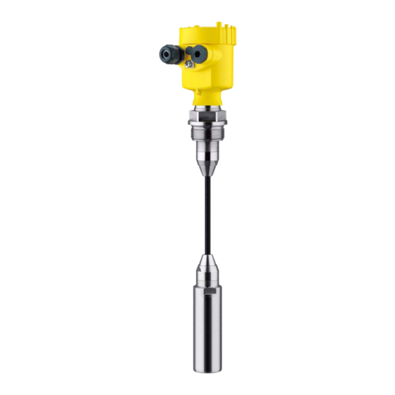
Submersible pressure transmitter with metal measuring cell
Hide thumbs
Also See for VEGABAR 87:
- Operating instructions manual (84 pages) ,
- Quick setup manual (24 pages) ,
- Operating instructions manual (80 pages)

Subscribe to Our Youtube Channel
Related Manuals for Vega VEGABAR 87


Summary of Contents for Vega VEGABAR 87
- Page 1 Operating Instructions Submersible pressure transmitter with metal measuring cell VEGABAR 87 Foundation Fieldbus Document ID: 45048...
-
Page 2: Table Of Contents
Saving the parameterisation data ................... 42 Setup with PACTware ......................43 Connect the PC ......................43 Parameter adjustment with PACTware ................43 Saving the parameterisation data ................... 44 Set up with other systems ....................45 DD adjustment programs ....................45 VEGABAR 87 • Foundation Fieldbus... - Page 3 11.6 Industrial property rights ....................74 11.7 Trademark ........................74 Safety instructions for Ex areas Take note of the Ex specific safety instructions for Ex applications. These instructions are attached as documents to each instrument with Ex approval and are part of the operating instructions. Editing status: 2020-05-12 VEGABAR 87 • Foundation Fieldbus...
-
Page 4: About This Document
Symbols used Document ID This symbol on the front page of this instruction refers to the Docu- ment ID. By entering the Document ID on www.vega.com you will reach the document download. Information, note, tip: This symbol indicates helpful additional infor- mation and tips for successful work. -
Page 5: For Your Safety
During work on and with the device, the required personal protective equipment must always be worn. Appropriate use Model VEGABAR 87 is a pressure transmitter for level and gauge measurement. You can find detailed information about the area of application in chapter "Product description". Operational reliability is ensured only if the instrument is properly used according to the specifications in the operating instructions manual as well as possible supplementary instructions. -
Page 6: Namur Recommendations
That is why we have introduced an environment management system with the goal of continuously improving company environmental pro- tection. The environment management system is certified according to DIN EN ISO 14001. Please help us fulfil this obligation by observing the environmental instructions in this manual: • Chapter "Packaging, transport and storage" • Chapter "Disposal" VEGABAR 87 • Foundation Fieldbus... -
Page 7: Product Description
The scope of delivery encompasses: • VEGABAR 87 pressure transmitter The further scope of delivery encompasses: • Documentation – Quick setup guide VEGABAR 87 – Test certificate for pressure transmitters – Instructions for optional instrument features – Ex-specific "Safety instructions" (with Ex versions) – If necessary, further certificates Information: Optional instrument features are also described in this operating instructions manual. -
Page 8: Principle Of Operation
Alternatively, you can access the data via your smartphone: • Download the VEGA Tools app from the "Apple App Store" or the "Google Play Store" • Scan the DataMatrix code on the type label of the instrument or •... - Page 9 3 Product description Depending on the version, the VEGABAR 87 is also suitable for Electronic differential pressure electronic differential pressure measurement. For this, the instrument is combined with a slave sensor. Fig. 3: Electronic differential pressure measurement through Master/Slave combination You can find detailed information in the operating instructions of the respective slave sensor. The process pressure acts on the sensor element via the stainless Measuring system steel diaphragm and an internal transmission liquid.
-
Page 10: Packaging, Transport And Storage
3 Product description Fig. 4: Configuration of the METEC measuring cell with VEGABAR 87 ® Process diaphragm Isolating liquid FeNi adapter CERTEC measuring cell ® The measuring cell design depends on the selected pressure type. Pressure types Relative pressure: the measuring cell is open to the atmosphere. -
Page 11: Accessories
Slave sensors Slave sensors of VEGABAR series 80 enable in conjunction with VEGABAR 87 an electronic differential pressure measurement. VEGADIS 81 The VEGADIS 81 is an external display and adjustment unit for VEGA plics sensors. ® The VEGADIS adapter is an accessory part for sensors with double VEGADIS adapter chamber housings. - Page 12 3 Product description Welded sockets are used to connect the sensors to the process. Welded sockets and adapters Threaded adapters enable simple adaptation of sensors with stand- ard threaded fittings, e.g. to process-side hygiene connections. VEGABAR 87 • Foundation Fieldbus...
-
Page 13: Mounting
To maintain the housing protection, make sure that the housing lid is closed during operation and locked, if necessary. Screwing in Devices with threaded fitting are screwed into the process fitting with a suitable wrench via the hexagon. See chapter "Dimensions" for wrench size. VEGABAR 87 • Foundation Fieldbus... - Page 14 Make sure that the upper temperature limits stated in chapter "Technical data" for the environment of the electronics hous- ing and connection cable are not exceeded. Fig. 5: Temperature ranges Process temperature Ambient temperature VEGABAR 87 • Foundation Fieldbus...
-
Page 15: Ventilation And Pressure Compensation
4 Mounting Depending on the transmitter, the VEGABAR 87 is supplied with a Transport and mounting protection protective cap or a transport and mounting protection. Fig. 6: VEGABAR 87, transport and mounting protection Transmitter Transport and mounting protection Remove this protection after mounting and before setting up the instrument. - Page 16 Instruments in protection IP66/IP68 (1 bar) - ventilation via capillar- ies in non-detachable cable • Instruments with absolute pressure → Filter element - Position Turn the metal ring in such a way that the filter element points Ex-d version downward after installation of the instrument. This provides better protection against buildup. VEGABAR 87 • Foundation Fieldbus...
- Page 17 With relative pressure measuring ranges, the ambient pressure is detected and compensated by a reference sensor in the electronics. Fig. 9: Position of the filter element - gastight leadthrough Filter element Gas-tight leadthrough VEGABAR 87 • Foundation Fieldbus...
-
Page 18: Level Measurement
• Mount the instrument so that it is protected against pressure shocks from the stirrer External housing Configuration Fig. 11: Arrangement measurement loop, external housing Sensor Connection cable sensor, external housing External housing Signal cable VEGABAR 87 • Foundation Fieldbus... -
Page 19: Connecting To The Bus System
In the case of instrument housings with self-sealing NPT threads, it is not possible to have the cable entries screwed in at the factory. The free openings for the cable glands are therefore covered with red dust protection caps as transport protection. VEGABAR 87 • Foundation Fieldbus... -
Page 20: Connecting
6. Insert the wire ends into the terminals according to the wiring plan Note: Solid cores as well as flexible cores with wire end sleeves are insert- ed directly into the terminal openings. In case of flexible cores without end sleeves, press the terminal from above with a small screwdriver, the terminal opening is then free. When the screwdriver is released, the terminal closes again. VEGABAR 87 • Foundation Fieldbus... -
Page 21: Single Chamber Housing
Simulation switch ("1" = mode for simulation release) For external display and adjustment unit Ground terminal for connection of the cable screening Double chamber housing The following illustrations apply to the non-Ex as well as to the Ex-ia version. VEGABAR 87 • Foundation Fieldbus... - Page 22 6 7 8 Fig. 15: Connection compartment - double chamber housing Voltage supply, signal output For display and adjustment module or interface adapter For external display and adjustment unit Ground terminal for connection of the cable screening VEGABAR 87 • Foundation Fieldbus...
-
Page 23: Double Chamber Housing With Vegadis-Adapter
Fig. 17: View to the plug connector M12 x 1 Pin 1 Pin 2 Pin 3 Pin 4 Contact pin Colour, connection ca- Terminal, electronics ble in the sensor module Pin 1 Brown Pin 2 White Pin 3 Blue Pin 4 Black VEGABAR 87 • Foundation Fieldbus... -
Page 24: Housing Ip66/Ip68 (1 Bar)
Brown (+) and blue (-) to power supply or to the processing system Shielding External housing Terminal compartment, housing socket 1 2 3 4 Fig. 19: Connection of the process component in the housing base Yellow White Black Shielding Breather capillaries VEGABAR 87 • Foundation Fieldbus... -
Page 25: Switch-On Phase
After connecting the instrument to power supply or after a voltage recurrence, the instrument carries out a self-check: • Internal check of the electronics • Indication of a status message on the display or PC VEGABAR 87 • Foundation Fieldbus... - Page 26 5 Connecting to the bus system Then the actual measured value is output to the signal cable. The value takes into account settings that have already been carried out, e.g. default setting. VEGABAR 87 • Foundation Fieldbus...
-
Page 27: Set Up With The Display And Adjustment Module
The display and adjustment module is powered by the sensor, an ad- ditional connection is not necessary. Fig. 22: Installing the display and adjustment module in the electronics compart- ment of the single chamber housing VEGABAR 87 • Foundation Fieldbus... -
Page 28: Adjustment System
– Move to the menu overview – Confirm selected menu – Edit parameter – Save value • [->] key: – Change measured value presentation – Select list entry – Select menu items – Select editing position • [+] key: VEGABAR 87 • Foundation Fieldbus... -
Page 29: Measured Value Indication
[OK] will not be saved. Measured value indication Measured value indica- With the [->] key you can move between three different indication tion modes. In the first view, the selected measured value is displayed in large digits. In the second view, the selected measured value and a correspond- ing bargraph presentation are displayed. VEGABAR 87 • Foundation Fieldbus... -
Page 30: Parameter Adjustment - Quick Setup
[->] or [ESC] keys or automatically after 3 s Note: You can find a description of the individual steps in the quick setup guide of the sensor. You can find "Extended adjustment" in the next sub-chapter. Parameter adjustment - Extended adjustment For technically demanding measuring points, you can carry out extended settings in "Extended adjustment". VEGABAR 87 • Foundation Fieldbus... - Page 31 Application In this menu item you activate/deactivate the slave sensor for elec- tronic differential pressure and select the application. VEGABAR 87 can be used for process pressure and level measure- ment. Default setting is process pressure measurement. The mode can be changed in this adjustment menu.
- Page 32 20 % of the nominal measuring range, then no position correction is possible. Adjustment VEGABAR 87 always measures pressure independently of the pro- cess variable selected in the menu item "Application". To output the VEGABAR 87 • Foundation Fieldbus...
- Page 33 1. Select the menu item "Setup" with [->] and confirm with [OK]. Now select with [->] the menu item "Zero adjustment" and confirm with [OK]. 2. Edit the mbar value with [OK] and set the cursor to the requested position with [->]. VEGABAR 87 • Foundation Fieldbus...
- Page 34 [OK]. The span adjustment is finished. Min. adjustment level Proceed as follows: 1. Select the menu item "Setup" with [->] and confirm with [OK]. Now select with [->] the menu item "Adjustment", then "Min. adjustment" and confirm with [OK]. VEGABAR 87 • Foundation Fieldbus...
- Page 35 Linearisation A linearization is necessary for all vessels in which the vessel volume does not increase linearly with the level - e.g. a horizontal cylindri- cal or spherical tank - and the indication or output of the volume is required. Corresponding linearization curves are preprogrammed for these vessels. They represent the correlation between the level per- centage and vessel volume. The linearization applies to the measured value indication and the current output. VEGABAR 87 • Foundation Fieldbus...
- Page 36 This menu item enables the setting of the requested national lan- guage. The following languages are available: • German • English • French • Spanish • Russian • Italian • Dutch • Portuguese • Japanese • Chinese • Polish VEGABAR 87 • Foundation Fieldbus...
- Page 37 6 Set up with the display and adjustment module • Czech • Turkish In delivery status, the VEGABAR 87 is set to English. Display value 1 and 2 In this menu item, you define which measured value is displayed. The default setting for the display value is "Lin. percent". Display format 1 and 2 In this menu item you define the number of decimal positions with which the measured value is displayed.
- Page 38 In this menu item, you adjust the internal clock of the sensor. There is no adjustment for summer/winter (daylight saving) time. Reset After a reset, certain parameter adjustments made by the user are reset. The following reset functions are available: VEGABAR 87 • Foundation Fieldbus...
- Page 39 Ceramic measuring cell: Measuring cell temperature in °C Metallic measuring cell: Electronics temperature in °C Display format 1 and 2 Number of positions after the decimal point, automatically Backlight Switched on Diagnostics Menu item Parameter Default value Sensor status VEGABAR 87 • Foundation Fieldbus...
- Page 40 The data are saved only after release. Special parameters In this menu item you gain access to the protected area where you can enter special parameters. In exceptional cases, individual VEGABAR 87 • Foundation Fieldbus...
- Page 41 PC. Device ID In this menu item, the identification number of the instrument in a Foundation Fieldbus system is shown. Sensor characteristics In this menu item, the features of the sensor such as approval, pro- cess fitting, seal, measuring range, electronics, housing and others are displayed. VEGABAR 87 • Foundation Fieldbus...
-
Page 42: Saving The Parameterisation Data
In the display and adjust- If the instrument is equipped with a display and adjustment module, ment module the parameter adjustment data can be saved therein. The procedure is described in menu item "Copy device settings". VEGABAR 87 • Foundation Fieldbus... -
Page 43: Setup With Pactware
Further setup steps are described in the operating instructions manu- al "DTM Collection/PACTware" attached to each DTM Collection and which can also be downloaded from the Internet. Detailed descrip- tions are available in the online help of PACTware and the DTMs. VEGABAR 87 • Foundation Fieldbus... -
Page 44: Saving The Parameterisation Data
The standard version is available as a download under www.vega.com/downloads and "Software". The full version is avail- able on CD from the agency serving you. Saving the parameterisation data We recommend documenting or saving the parameterisation data via PACTware. -
Page 45: Set Up With Other Systems
8 Set up with other systems Set up with other systems DD adjustment programs Device descriptions as Enhanced Device Description (EDD) are available for DD adjustment programs such as, for example, AMS↑ and PDM. The files can be downloaded at www.vega.com/downloads under "Software". VEGABAR 87 • Foundation Fieldbus... -
Page 46: Diagnosis, Asset Management And Service
Event memory Up to 500 events are automatically stored with a time stamp in the sensor (non-deletable). Each entry contains date/time, event type, event description and value. Event types are for example: • Modification of a parameter VEGABAR 87 • Foundation Fieldbus... -
Page 47: Asset Management Function
This status message is inactive by default. Maintenance required: Due to external influences, the instrument function is limited. The measurement is affected, but the measured value is still valid. Plan in maintenance for the instrument because a failure is expected in the near future (e.g. due to buildup). This status message is inactive by default. VEGABAR 87 • Foundation Fieldbus... - Page 48 Repeat reset settings F264 Inconsistent settings (e.g.: dis- Modify settings Bit 10 tance, adjustment units with Installation/Setup error Modify connected sensor config- application process pressure) for uration or application selected application Invalid sensor configuration (e.g.: application electronic differential pressure with connected differen- tial pressure measuring cell) VEGABAR 87 • Foundation Fieldbus...
- Page 49 Hardware error EEPROM Exchanging the electronics Bit 17 Error in the event Send instrument for repair memory M504 Hardware defect Exchanging the electronics Bit 19 Error at a device in- Send instrument for repair terface VEGABAR 87 • Foundation Fieldbus...
-
Page 50: Rectify Faults
24 hour service hotline Should these measures not be successful, please call in urgent cases the VEGA service hotline under the phone no. +49 1805 858550. The hotline is also available outside normal working hours, seven days a week around the clock. -
Page 51: Exchanging The Electronics Module
9 Diagnosis, asset management and service 2. Carefully detach the cable assembly from the process module Fig. 30: VEGABAR 87 in IP68 version, 25 bar and lateral cable outlet, external housing Process module Plug connector Cable assembly Connection cable External housing 3. -
Page 52: How To Proceed If A Repair Is Necessary
Clean the instrument and pack it damage-proof • Attach the completed form and, if need be, also a safety data sheet outside on the packaging • Ask the agency serving you to get the address for the return ship- ment. You can find the agency on our homepage. VEGABAR 87 • Foundation Fieldbus... -
Page 53: Dismount
Pass the instrument directly on to a specialised recycling company and do not use the municipal collecting points. If you have no way to dispose of the old instrument properly, please contact us concerning return and disposal. VEGABAR 87 • Foundation Fieldbus... -
Page 54: Supplement
Ʋ Erdungsklemme 316L Externes Gehäuse - abweichende Werkstoffe Ʋ Gehäuse und Sockel Kunststoff PBT (Polyester), 316L Ʋ Sockeldichtung EPDM Ʋ Dichtung unter Wandmontageplatte EPDM Ʋ Sichtfenster Gehäusedeckel Polycarbonat (UL746-C gelistet) Erdungsklemme 316Ti/316L Glas bei Aluminium- und Edelstahl Feingussgehäuse Nur bei 316L mit 3A-Zulassung VEGABAR 87 • Foundation Fieldbus... - Page 55 0 … 2.5 bar/0 … 250 kPa 25 bar/+2500 kPa 0 bar abs. 0 … 10 bar/0 … 1000 kPa 25 bar/+2500 kPa 0 bar abs. Zwischen Messwertaufnehmer und externem Elektronikgehäuse. Data on overload capability apply for reference temperature. VEGABAR 87 • Foundation Fieldbus...
- Page 56 Unlimited (recommended 20 : 1) Switch-on phase Start-up time with operating voltage U Ʋ ≥ 12 V DC ≤ 9 s Ʋ < 12 V DC ≤ 22 s Output variable Output signal digital output signal, Foundation Fieldbus protocol Transmission rate 31.25 Kbit/s VEGABAR 87 • Foundation Fieldbus...
- Page 57 ±4 K and +100 … +150 °C (+212 … +302 °F) Output of the temperature values Ʋ Indication Via the display and adjustment module Ʋ Analogue Via the current output, the additional current output VEGABAR 87 • Foundation Fieldbus...
- Page 58 The basic temperature error in % from the above graphic can increase due to the additional factors, depending on the measuring cell version (factor FMZ) and the Turn Down (factor FTD). The ad- ditional factors are listed in the following tables. VEGABAR 87 • Foundation Fieldbus...
- Page 59 -20 … +80 °C (-4 … +176 °F) -20 … +80 °C (-4 … +176 °F) Ausführung IP68 (1 bar) mit An- -20 … +60 °C (-4 … +140 °F) -20 … +60 °C (-4 … +140 °F) schlusskabel PE VEGABAR 87 • Foundation Fieldbus...
- Page 60 Ʋ Min. bending radius at 25 °C/77 °F 25 mm (0.985 in) Depending on the instrument version. 2 g with housing version stainless steel double chamber. IP66/IP68 (0.2 bar), only with absolute pressure. Breather capillaries not with Ex-d version. VEGABAR 87 • Foundation Fieldbus...
- Page 61 – ● Interface to the slave sensor Data transmission Digital (I²C-Bus) Configuration, connection cable 4-wire, shielded Max. cable length 25 m Integrated clock Date format Day.Month.Year Time format 12 h/24 h Time zone, factory setting Max. rate deviation 10.5 min/year VEGABAR 87 • Foundation Fieldbus...
- Page 62 IP68 (25 bar) nal housing Connection of the feeding power supply Networks of overvoltage category III unit Galvanic separation between electronics and metal housing parts Protection rating IP66/IP68 (0.2 bar) only in conjunction with absolute pressure. VEGABAR 87 • Foundation Fieldbus...
-
Page 63: Device Communication Foundation Fieldbus
0.8 V P-P Electrical Connection 2 Wire Polarity Insensitive Max. Current Load 11 mA Device minimum operating voltage Transmitter Function Blocks Resource Block (RB) Transducer Block (TB) Standard Block (AI) Execution Time 30 mS When used with fulfilled housing protection. VEGABAR 87 • Foundation Fieldbus... -
Page 64: Calculation Of The Total Deviation
: Basic deviation perf • : Long-term stability stab • : Thermal change of zero signal and output span (temperature error) • : Deviation • : Thermal change of the current output • FMZ: Additional factor measuring cell version • FTD: Additional factor Turn down VEGABAR 87 • Foundation Fieldbus... -
Page 65: Praxisbeispiel
= 0,26 % 3. Ermittlung Messabweichung und Langzeitstabilität Die erforderlichen Werte für Messabweichung F und Langzeitstabilität F werden den technis- stab chen Daten entnommen: Genauigkeitsklasse Nichtlinearität, Hysterese und Nichtwiederholbarkeit TD ≤ 5 : 1 TD > 5 : 1 0,1 % < 0,1 % < 0,02 % x TD VEGABAR 87 • Foundation Fieldbus... -
Page 66: Dimensions
Messabweichung in mm: 0,41 % von 1600 mm = 7 mm Das Beispiel zeigt, dass der Messfehler in der Praxis deutlich höher sein kann, als die Grundgenauigkeit. Ursachen sind Temperatureinfluss und Turn Down. 11.5 Dimensions The following dimensional drawings represent only an extract of the possible versions. Detailed dimensional drawings can be downloaded at www.vega.com under "Downloads" and "Drawings". VEGABAR 87 • Foundation Fieldbus... - Page 67 M20x1,5/ ½ NPT Fig. 35: Housing versions with protection rating IP66/IP68 (0.2 bar), (with integrated display and adjustment mod- ule the housing is 18 mm/0.71 in higher) Aluminium - single chamber Aluminium - double chamber VEGABAR 87 • Foundation Fieldbus...
- Page 68 Fig. 37: Housing versions in protection rating IP66/IP68 (0.2 bar), (with integrated display and adjustment module the housing is 9 mm/0.35 in or 18 mm/0.71 in higher) Stainless steel single chamber (electropolished) Stainless steel single chamber (precision casting) Stainless steel double chamber housing (precision casting) VEGABAR 87 • Foundation Fieldbus...
- Page 69 ~ 59 mm (2.3") ø 80 mm (3.15") M20x1,5/ ½ NPT Fig. 39: Housing version with protection rating IP69K (with integrated display and adjustment module the housing is 9 mm/0.35 in higher) Stainless steel single chamber (electropolished) VEGABAR 87 • Foundation Fieldbus...
- Page 70 8 mm (0.12") (0.32") 110 mm x 90 mm (4.33" x 3.54") Fig. 40: VEGABAR 87, IP68 version with external housing Lateral cable outlet Axial cable outlet Plastic single chamber Stainless steel single chamber Seal 2 mm (0.079 in), (only with 3A approval)
- Page 71 G1 ½ / 1½ NPT 1½ NPT ø 8 mm (0.32") ø 29 mm (1.14") ø 40 mm (1.58") Fig. 41: VEGABAR 87, standard fittings Straining clamp Threaded fitting Thread G1½ Thread 1½ NPT Lock fitting VEGABAR 87 • Foundation Fieldbus...
- Page 72 6 " 0.12 " 3" 0.75 " 4" 10" 1 .25" 7.87 " 8xø0.63 " 6.19 " 0.12 " Fig. 42: VEGABAR 87, flange connection Flanges according to DIN 2501 Flanges according to ASME B16.5 VEGABAR 87 • Foundation Fieldbus...
- Page 73 ø 64 mm (2.52") ø 92 mm (3.62") ø 8 mm (0.32") ø 40 mm (1.58") Fig. 43: VEGABAR 87, hygienic fittings Clamp 2" PN 16 (ø 64 mm) DIN 32676, ISO 2852 Slotted nut DN 50 VEGABAR 87 • Foundation Fieldbus...
-
Page 74: Industrial Property Rights
Les lignes de produits VEGA sont globalement protégées par des droits de propriété intellec- tuelle. Pour plus d'informations, on pourra se référer au site www.vega.com. VEGA lineas de productos están protegidas por los derechos en el campo de la propiedad indus- trial. Para mayor información revise la pagina web www.vega.com. - Page 75 – Rectification 50 Fault rectification 50 Functional principle 9 Level measurement 18 Linearisation 35 Maintenance 46 Measured value memory 46 Measurement setup – In the open vessel 18 NAMUR NE 107 47 Parameterization example 32 Peak value indicator 37, 38 VEGABAR 87 • Foundation Fieldbus...
- Page 76 Subject to change without prior notice © VEGA Grieshaber KG, Schiltach/Germany 2020 VEGA Grieshaber KG Phone +49 7836 50-0 Am Hohenstein 113...
Need help?
Do you have a question about the VEGABAR 87 and is the answer not in the manual?
Questions and answers