
Related Manuals for SKF ATEX RA Series


Summary of Contents for SKF ATEX RA Series
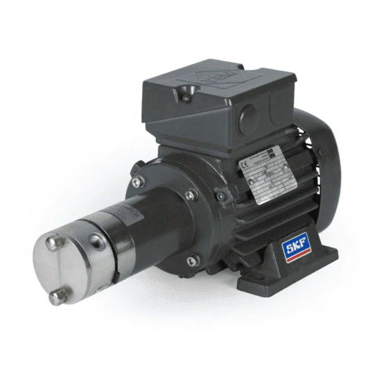
- Page 1 ATEX multiline pumps of series RA Operating instructions according to ATEX Directive 2014/34/EU Version 01 951-180-082-EN...
-
Page 2: Eu Declaration
EU Declaration of Conformity EU Declaration of Conformity pursuant to ATEX Directive 2014/34/EU, Annex X The manufacturer, SKF Lubrication Systems Germany GmbH, Hockenheim Plant, 2. Industriestr. 4, DE - 68766 Hockenheim hereby de- clares the conformity of the device: Designation:... -
Page 3: Masthead
Masthead Manufacturer Training Disclaimer of liability SKF Lubrication Systems Germany GmbH SKF conducts detailed training in order to The manufacturer shall not be held liable for enable the maximum safety and efficiency. damage resulting from: Address of manufacturer plants Headquarters SKF recommends taking advantage of this ○... -
Page 4: Table Of Contents
Table of contents Table of contents EU Declaration Masthead 3 1.21 Protective and safety mechanisms Explanation of symbols and signs 1.22 Special safety instructions regarding explosion protection 1.23 Nullification of ATEX approval Safety instructions 1.24 Operation in potentially explosive atmospheres General safety instructions 1.26 Obligations of the operator... - Page 5 Table of contents 4.1.4 Explanation of order codes for rotary drive (RA1UA) 4.5.1 Fill level control for grease with changeover function K (E) 4.1.5 Explanation of order codes for rotary drive with 4.5.2 Fill level switch with NC/NO function for grease (F) coaxial gear (RA2UB) Tightening torques 4.1.6 Explanation of order codes for rotary drive with...
- Page 6 Table of contents Cleaning 6.5.1 RA rotary drive Cleaning agents 6.5.2 RA electric motor drive Exterior cleaning Electrical connection Interior cleaning 6.6.1 Establish the motor connection RA multiline pump units with electric motor drive 6.6.2 Establishing equipotential bonding connection Electrical connection of fill level controls Maintenance 6.7.1 Connection for fill level control K (E) 10.1...
-
Page 7: Explanation Of Symbols And Signs
Explanation of symbols, signs, and abbreviations Explanation of symbols and signs General warning Risk of electrical shock Risk of slipping Hot surfaces Being drawn into machinery Crushing hazard Pressure injection Suspended load Electrostatic sensitive Potentially explosive Disposal, recycling components atmosphere Wear personal protective gear Wear personal protective gear Wear personal protective gear... - Page 8 Explanation of symbols, signs, and abbreviations Abbreviations and conversion factors regarding °C degrees Celsius °F degrees Fahrenheit approx. approximately Kelvin ounce i.e. that is Newton fl. oz. Fluid ounce etc. et cetera hour inch incl. including second pound per square inch min.
-
Page 9: Safety Instructions
1st Safety instructions 1. Safety instructions 1.1 General safety instructions 1.2 General behavior when handling the product ○ The operator must ensure that the in- ○ The product may only be used in aware- ○ Responsibilities for different activities structions are read by all persons tasked ness of the potential dangers, in proper must be clearly defined and observed. -
Page 10: Intended Use
1st Safety instructions 1.3 Intended use ○ Use in areas with damaging radiation Intended use is the use of the RA multiline Third-party products, such as ATEX motors pump for the purpose of providing central- or drives, attached to a rotary RA multline (e.g., ionizing radiation) ized lubrication. -
Page 11: Painting Plastic Components
1st Safety instructions 1.6 Modiications to the product 1.8 Inspections prior to delivery ○ Use in potentially explosive dusts whose minimum ignition temperature and glow Unauthorized modifications and changes The following tests were performed prior to temperature are less than 150% of the can have an unpredictable effect on safety. - Page 12 1st Safety instructions If necessary: ○ Project planning documents ○ Instructions from suppliers of purchased parts ○ Instructions for other components for setting up the centralized lubrication system ○ Other relevant documents for integration of the product into the main machine, system ○...
-
Page 13: Markings On The Product
1st Safety instructions 1.10 Markings on the product The following warning labels are affixed to Positioning of warning labels, Fig. 1 the motor-driven RA multiline pumps. Be- fore start-up, check that the labels are pres- I t e m 1 ent and intact. -
Page 14: Notes On The Rating Plate
_______°C ≤ Ta ≤ _______°C 1.13 Persons authorized to use the Note on Low-Voltage Directive 2014/35/EU product The protection objectives of Low-Voltage SKF Lubrication Systems Germany GmbH 1.13.1 Operator Directive 2014/35/EU are met in accordance KW/JJ with Annex II, No. 1.2.7 of ATEX 2014/34/EU. -
Page 15: Qualified Mechanic
1st Safety instructions 1.13.2 Qualiied mechanic 1.15 Provision of personal protective gear A person with appropriate technical train- rectify these by taking suitable actions. The The operator must provide personal protec- ing, knowledge, and experience who can specialist has knowledge of the various types tive gear appropriate for the location and recognize and avoid the hazards that may of protection, installation procedures, and... -
Page 16: Emergency Shutdown
1st Safety instructions 1.17 Emergency shutdown 1.18 Transport, assembly, maintenance, malfunction, repair, shutdown, disposal ○ All relevant persons must be informed of Shut down the product in an emergency by: during the work and that no limbs can be the activity prior to the start of this work. pinched by unintended movements. - Page 17 Do not damage lines or cables ○ Lubrication lines should be filled with when drilling. Modifications to SKF prod- ucts are prohibited. This also includes lubricant prior to assembly. This simplifies subsequent venting of the system.
-
Page 18: First Start-Up, Daily Start-Up
1st Safety instructions 1.19 First start-up, daily start-up 1.20 Cleaning 1.21 Protective and safety mechanisms ○ There is a fire hazard from the use of ○ Protective and safety mechanisms can- Ensure that: flammable cleaning agents. Use only not be removed, modified, nor disabled ○... -
Page 19: Special Safety Instructions Regarding Explosion Protection
1st Safety instructions 1.22 Special safety instructions regarding explosion protection ○ Always behave so as to avoid explosion shipping damage, do not install or put greater than 150% of the maximum sur- hazards. into operation the product. face temperature. ○ A written work authorization from the ○... - Page 20 1st Safety instructions filling pump must be connected to the - Type of repair tion by hand using the provided locking equipotential bonding connection of the - If applicable, mark by expert clips. pump. ○ Shipping damage may lead to the loss of ○...
-
Page 21: Nullification Of Atex Approval
○ Unauthorized alterations and the cable glands properly sealed. ○ All information within this manual and ○ Any additional electrical monitoring ○ Use of non-original SKF spare/replace- the information within the referenced equipment must be securely connected ment components documents and correctly configured. -
Page 22: Obligations Of The Operator
1st Safety instructions 1.25 Explosion protection marking 1.26.2 Explosion protection measures ○ Selects suitable employees The explosion protection marking is located Based on a comprehensive assessment of on the Declaration of Conformity and on the the work area, the operator ensures that the ○... -
Page 23: Provision Of Necessary Information
1st Safety instructions 1.26.3 Provision of necessary information 1.26.4 Duty to provide instruction and training ○ Avoidance of hazards when handling the The operator must the relevant required product and the main machine instructions available to all persons assigned The operator clearly defines the responsibili- ○... -
Page 24: Residual Risks
1st Safety instructions 1.27 Residual risks Possible in Residual risk Avoidance / Remedy lifecycle Personal injury / property damage due to Unauthorized persons must be kept away; nobody is allowed to be present below hoisted parts. A, B, C, G, H, K falling of hoisted parts Lift parts using suitable and tested lifting gear. -
Page 25: Residual Atex Risks
1st Safety instructions 1.28 Residual ATEX risks Possible in Residual risk Avoidance / Remedy lifecycle Use in a potentially explosive atmosphere Check the equipotential bonding for continuity before first start-up, after every repair, and ad- without checking equipotential bonding C, D, G ditionally at regular intervals defined by the operator for electrical continuity Operation with a damaged, missing, or... - Page 26 1st Safety instructions Possible in Residual risk Avoidance / Remedy lifecycle Generation of electrostatic charges or sparks by C, D, E, F, G Secure parts against falling. if necessary, cover parts to avoid sparking dropping of parts Introduction of catalytic, unstable, or pyro- Ensure that none of these substances enter the potentially explosive atmosphere;...
-
Page 27: Lubricants
2. Lubricants 2.1 General information 2.2 Selection of lubricants Lubricants are used specially for specific SKF Lubrication Systems considers lubri- applications. To fulfill the task, lubricants cants to be an element of system design. Only lubricants specified for the must meet various requirements to varying The selection of a suitable lubricant should product may be used (see “Technical... -
Page 28: Material Compatibility
It is possible for lubricants to be tested in the company's laboratory for their suitability for pumping in centralized lubrication systems (e.g., "bleeding"). Please contact SKF if you have further ques- tions regarding lubricants. An overview of the lubricants we have tested is available on request. -
Page 29: Overview, Functional Description
3. Overview, functional description 3. Overview, functional description 3.1 Assembly Rotary drive, Fig. 2 Item Description Radial piston pump Initial section Pump element Sealing cap Tie-rod with cap nut Coaxial gear -Rotary, coaxial Bevel gear Grease reservoir Electrical fill level switch (K/F) Visual max. - Page 30 3. Overview, functional description Item Description Electric motor drive, Fig. 3 Radial piston pump Initial section Pump element Sealing cap Tie-rod with cap nut (2x) Electric motor Motor foot Terminal box -Coaxial Electric motor drive, coaxial -Chapter 4.2.1 and Chapter 6.3.1 Electric motor drive with Coaxial gear -Chapter 4.2.2 and Chapter 6.3.5...
- Page 31 3. Overview, functional description Electric motor drive, with grease reservoir, Fig. 4 Item Description Radial piston pump Gear (coaxial/bevel) Initial section Pump element Electric motor Motor foot Terminal box Grease reservoir Electrical fill level switch (K/F) Visual max. level gauge Cables for potential equalization Electric motor drive with coaxial gear and grease reservoir with fill...
-
Page 32: Functional Description
3. Overview, functional description 3.2 Functional description The RA multiline pump is constructed as a Its operating pressure is max. 63 bar, with IMPORTANT NOTE radial piston pump in a modular design. Up up to 100 bar for short periods. to five pump elements each with The design of the RA multiline pump permits The RA multiline pump may be operated... -
Page 33: Operation Of The Ra Multline Pump
3. Overview, functional description 3.3 Operation of the RA multline pump )See Figure 5 As the pump shaft turns, the two pump pis- The stroke of the two pistons remains the tons move apart due to the spring loading, same in every phase variation; it is fully ef- In its basic design, the RA multiline pump is until the outer dead center is reached. - Page 34 3. Overview, functional description Pump element in the pressure phase, Fig. 5 Example Tie-rods with cap nut 1 Pump ring Outlet 2 Pump shaft Spacer ring 6 Spring Banjo fitting Pump element Part No. 24-2106-2390 5 Adjusting plate Inlet 4 Track ring Drive 3 Pump piston Pressure relief valve...
-
Page 35: Technical Data
4. Technical data 4. Technical data 4.1 Design with rotary drive 4.1.1 Rotary, coaxial (RA1UA) 4.1.2 Rotary with coaxial gear (RA2UB) 4.1.3 Rotary with bevel gear (RA3UA) Version Unit RA1UA / RA2UB / RA3UA zone 1 II 2G Ex h IIC T4 Gb Explosion protection marking II 2D Ex h IIIC T135°C Db zone 21... - Page 36 4. Technical data Version Unit RA1UA / RA2UB / RA3UA Lubricant temperature range °C -20 to +60 Operating viscosity 25 to 2500 ≥5 to ≤10 Lubricant purity level (OIL) µm ≥ 4 Intake tube inside diameter and Max. suction head Version RA1UA / RA2UB / RA3UA RA1UA (number of elements)
-
Page 37: Explanation Of Order Codes For Rotary Drive (Ra1Ua)
4. Technical data 4.1.4 Explanation of order codes for rotary drive (RA1UA) 4.1.5 Explanation of order codes for rotary drive with coaxial gear (RA2UB) RA 1UA 00 / 4 4 2 X X R 4xxx RA 2UB 15 / 4 4 1 2 5 D R 4xxx Example: Example: Type... -
Page 38: Explanation Of Order Codes For Rotary Drive With Bevel Gear (Ra3Ua)
4. Technical data 4.1.6 Explanation of order codes for rotary drive with bevel gear (RA3UA) RA 3UA 01 A 4 2 4 4 1 R 4xxx Example: Type Radial piston pump Drive = Rotary, bevel gear Reduction ratio = 10.5:1 Drive position A or B -See Figure 9, page 59... -
Page 39: Design With Electric Motor Drive
4. Technical data 4.2 Design with electric motor drive 4.2.1 Electric motor drive, coaxial (RA1M) 4.2.2 Electric motor drive, with coaxial gear (RA2M) 4.2.3 Electric motor drive, with bevel gear (RA3M) Version Unit RA1M / RA2M / RA3M ATEX protection type, depending on ATEX Zone 1 II 2G Ex h IIC T4 Gb motor certification:... - Page 40 4. Technical data Version Unit RA1UA / RA2UB / RA3UA ≥5 to ≤10 Lubricant purity level (OIL) µm ≥ 4 Intake tube inside diameter and Max. suction head Motor frequency 50 (standard), 60 on request Motor data for 50 Hz motors see pages 41 and 42 Version RA1M / RA2M / RA3M...
- Page 41 Order codes II 2D Ex tb IIIC T125°C Db [kW] [Nm] [IEC/EN60034-30-1] [400V] [kg] Order code 100% 69.9 68.0 62.2 0.70 0.60 IE3-KPR 63 G4 Ex II2D 0.18 1.22 1405 IE3- SKF item number: 84-5510-4802 - 41 - 951-180-082-EN Version 01...
- Page 42 Rated speed 1415 rpm ATEX / type lange Frame size/ Order codes II 2G Ex d/de IIC T4 Gb [kW] [Nm] [400V] [kg] Order code K82R63 Mx4 0.18 1415 0.70 0.53 SKF item number: 84-5510-4803 - 42 - 951-180-082-EN Version 01...
-
Page 43: Explanation Of Orders Codes For Electric Motor Drive, Coaxial (Ra1M)
4. Technical data 4.2.4 Explanation of orders codes for electric motor drive, coaxial (RA1M) RA 1M 00 4 4 2 XX 4xxx AF 07 Example: Type Radial piston pump Drive Electric motor, coaxial Reduction ratio = 1:1 Number of outlets per pump element = 1 outlet 2 outlets = 4 outlets... -
Page 44: Explanation Of Order Codes For Electric Motor Drive With Coaxial Gear (Ra2M)
4. Technical data 4.2.5 Explanation of order codes for electric motor drive with coaxial gear (RA2M) 2M 15 4 4 4 2 1 / R 4xxx AF 07 Example: Type Radial piston pump Drive Electric motor, with coaxial gear Reduction ratio 15 = 25 = = 5:1... -
Page 45: Explanation Of Order Codes For Electric Motor Drive With Bevel Gear (Ra3M)
4. Technical data 4.2.6 Explanation of order codes for electric motor drive with bevel gear (RA3M) 3M 01 4 4 4 2 1 4xxx AF 07 Example: Type Radial piston pump Drive Electric motor, with bevel gear Reduction ratio = 10.5:1 Number of outlets per pump element = 1 outlet 2 outlets... -
Page 46: Design With Rotary Drive, With Grease Reservoir
4. Technical data 4.3 Design with rotary drive, with grease reservoir 4.3.1 Rotary drive, with bevel gear and grease reservoir (RA...3UA) Version Unit zone 1 II 2G Ex h IIC T4 Gb Explosion protection marking zone 21 II 2D Ex h IIIC T135°C Db Mounting position Vertical, reservoir upwards Permissible ambient temperature... -
Page 47: Explanation Of Order Codes For Rotary Drive, With Bevel Gear And Grease Reservoir (Ra
4. Technical data 4.3.2 Explanation of order codes for rotary drive, with bevel gear and grease reservoir (RA...3UA) 3UA 01 B 4 4 4 4xxx Example: Type Radial piston pump Reservoir capacity 4.5kg = 2 kg Fill level switch With 2 switching points and With 3 switching points visual maximum fill indicator (in lid) Drive... -
Page 48: Design With Electric Motor Drive, With Grease Reservoir
4. Technical data 4.4 Design with electric motor drive, with grease reservoir 4.4.1 Electric motor drive, with coaxial gear and grease reservoir (RA...2M) 4.4.2 Electric motor drive, with bevel gear and grease reservoir (RA...3M) Version Unit RA20F2M / RA20F3M II 2G Ex h IIC T4 Gb Explosion protecting marking, depending on ATEX motor zone 1 certification:... - Page 49 4. Technical data Version Unit RA20F2M / RA20F3M Operating viscosity 25 to 2500 ≤ 2 Lubricating greases NLGI Grade Lubricant filling Via fill connection Pump weight of RA...2M without motor, motor weights - With 2 kg grease reservoir: Element 1: 7.42 / 2: 7.81 / 3: 8.20 kg (approx.) see Technical data for the motors With 4.5 kg grease reservoir: Element 1: 7.72 / 2: 8.11 / 3: 8.50...
-
Page 50: Explanation Of Order Codes For Electric Motor Drive, With Coaxial Gear And Grease Reservoir (Ra
4. Technical data 4.4.3 Explanation of order codes for electric motor drive, with coaxial gear and grease reservoir (RA...2M) 15 4 4 4 4xxx AF 07 Example: Type Radial piston pump Reservoir capacity = 2 kg 4.5kg Fill level switch With 2 switching points and With 3 switching points visual maximum fill indicator (in lid) -
Page 51: Explanation Of Order Codes For Electric Motor Drive, With Bevel Gear And Grease Reservoir (Ra
4. Technical data 4.4.4 Explanation of order codes for electric motor drive, with bevel gear and grease reservoir (RA...3M) 01 1 2 4 4xxx AF 07 Example: Type Radial piston pump Reservoir capacity 4.5kg = 2 kg Fill level switch With 2 switching points and With 3 switching points visual maximum fill indicator (in lid) -
Page 52: Fill Level Control
4. Technical data 4.5 Fill level control 4.5.2 Fill level switch with NC/NO 4.6 Tightening torques function for grease (F) )See instructions in Chapter 6.7, “Electrical Tightening torques )Wiring diagram, see Chapter 6.7.2 connection of fill level controls.” The specified torques must be observed during Fill level switch F assembly and maintenance. -
Page 53: Supply, Returns, Storage
5. Delivery, returns, storage 5. Supply, returns, storage 5.1 Supply 5.2 Return shipment 5.3 Storage After receipt of the supply, it must be in- Before return shipment, all contaminated Before usage, check products for spected for any shipping damage and for parts must be cleaned and properly packed damage that may have occurred completeness according to the shipping... -
Page 54: Corrosion Protection
5. Delivery, returns, storage 5.3.1 Corrosion protection 5.3.2 Special storage conditions for motors ○ Do not store motors on the fan cowl. ○ Protected from nearby sources of heat The corrosion protection (e.g., on the inside ○ Be sure to inspect insulation resistance of or cold of the container) should be checked and (if applicable) renewed every 6 - 12 months... -
Page 55: Assembly
6. Assembly 6. Assembly 6.1 General information on assembly ○ Other units must not be damaged by as- ○ Prior to beginning installation, inspect the DANGER sembly work. full scope of delivery of the RA multline pump unit for any damage or corrosion. Explosion ○... -
Page 56: Assembly Location
6. Assembly 6.2 Assembly location The product should, to the extent possible, dry, SKF recommends a fill level control with Installation examples, Fig. 6 be protected from humidity and vibration, a minimum switching point. RA, self-priming and should be mounted so that it is easily... -
Page 57: Ra Oil And Grease Lubrication Pumps
6. Assembly 6.3 RA oil and grease lubrication pumps 6.3.1 Rotary drive, coaxial (RA1UA) Assembly drawing with minimum installation dimensions, Fig. 7 220.5 28.5 4 h9 32.5 Positioning of outlets I ... IV Inlet Inlet G1/8 Outlet G1/8 ø15.2 ø54 Minimum mounting dimensions -See dimensions marked red Number of pump elements [mm]... -
Page 58: Rotary Drive, With Coaxial Gear (Ra2Ub)
6. Assembly 6.3.2 Rotary drive, with coaxial gear (RA2UB) Assembly drawing with minimum installation dimensions, Fig. 8 28.5 Positioning of outlets I ... IV Inlet Inlet G1/8 Outlet G1/8 ø15.2 ø70 Gear ratio Approx. [mm] 52.3 Minimum mounting dimensions 15:1 62.6 -See dimensions marked red 25:1... -
Page 59: Rotary Drive, With Bevel Gear (Ra3Ua)
6. Assembly 6.3.3 Rotary drive, with bevel gear (RA3UA) Assembly drawing with minimum installation dimensions, Fig. 9 28.5 22.8 52.5 Drive position A Positioning of outlets I ... IV Outlet G1/8 ø15.2 Inlet G1/8 Drive position B Minimum mounting dimensions -See dimensions marked red 12.5 Number of pump elements [mm]... -
Page 60: Electric Motor Drive, Coaxial (Ra1M)
6. Assembly 6.3.4 Electric motor drive, coaxial (RA1M) Assembly drawing with minimum installation dimensions, Fig. 10 460.5 Positioning of outlets I ... IV 2x M25x1,5 244.5 Inlet G1/8 Outlet G1/8 Inlet ø15.2 4x ø7 127.5 20.5 *160 Minimum mounting dimensions -See dimensions marked red * = Motor dimensions for motor S No.: 84-5510-4802. -
Page 61: Electric Motor Drive, With Coaxial Gear (Ra2M)
6. Assembly 6.3.5 Electric motor drive, with coaxial gear (RA2M) Assembly drawing with minimum installation dimensions, Fig. 11 Gear ratio Approx. [mm] 150.8 15:1 161.1 Positioning of 25:1 161.1 outlets I ... IV 75:1 171.6 * 2x M25x1,5 125:1 171.6 Inlet G1/8 Outlet G1/8 Inlet... -
Page 62: Electric Motor Drive, With Bevel Gear (Ra3M)
6. Assembly 6.3.6 Electric motor drive, with bevel gear (RA3M) Assembly drawing with minimum installation dimensions, Fig. 12 ** with 5 pump elements Outlet G1/8 2x M25x1,5 Inlet G1/8 4x ø7 *160 Minimum mounting dimensions Positioning of -See dimensions marked red outlets I ... -
Page 63: Ra Grease Lubrication Pumps With Grease Reservoir
6. Assembly 6.4 RA grease lubrication pumps with grease reservoir 6.4.1 Rotary drive, with bevel gear and grease reservoir (RA...3UA) Assembly drawing with minimum installation dimensions, Fig. 13 Minimum mounting dimensions -See dimensions marked red [mm] ø 240 2 kg reservoir 117 mm 4.5 kg reservoir 197 mm... - Page 64 6. Assembly 6.4.2 Electric motor drive, with coaxial gear and grease reservoir (RA...2M) Assembly drawing with minimum installation dimensions, Fig. 14 Minimum mounting dimensions Positioning of -See dimensions marked red outlets I ... IV [mm] 2 kg reservoir 4.5 kg reservoir 2 kg reservoir L1+337 **L2...
- Page 65 6. Assembly 6.4.3 Electric motor drive, with bevel gear and grease reservoir (RA...3M) Assembly drawing with minimum installation dimensions, Fig. 15 Minimum mounting dimensions -See dimensions marked red [mm] 2 kg reservoir 4.5 kg reservoir **L2 2 kg reservoir Fill connection G3/8 4.5 kg reservoir **L3 * = Motor dimensions for motor S No.:...
-
Page 66: Assembly Of Ra Multiline Pumps
6. Assembly 6.5 Assembly of RA multiline pumps Requirement: • Carefully prepare the flanging surface and • Insert cheese-head screws (2x, M6, rec- The mounting surface for the RA multline assembly holes (2x Ø 6.5 mm) for the re- ommended engagement depth 12 mm) pump must be free of dust particles, ma- spective RA pump. -
Page 67: Ra Electric Motor Drive
6. Assembly 6.5.2 RA electric motor drive (type: RA1M; RA2M; RA3M; RA...2M; RA...3M) )Tightening torque table from the fitting • Fastening material provided by customer )See Chapters 6.3.4 to 6.3.6 in corrosion-protected design: manufacturer (suction and delivery screw See Chapters 6.4.2 to 6.4.3 union) ○... -
Page 68: Electrical Connection
6. Assembly 6.6 Electrical connection Observe the guidelines in DIN EN 60034-1 WARNING WARNING (VDE 0530-1) for operation at the limits of the A ranges (combination of ±10% voltage Electric shock Electric shock / damage to pump deviation and +3/-5% frequency deviation). Electrical connections for the motor This applies especially with regard to heating... - Page 69 6. Assembly IMPORTANT NOTE WARNING WARNING Mains connection for explosion- Damage to pump motor/pump Use only original cover fittings and original proof motors When establishing the electrical cable glands from the motor manufacturer. A mains connection in a potentially connection of the pump motor, be explosive atmosphere requires a mindful of the correct direction of motor circuit breaker or equivalent...
-
Page 70: Establish The Motor Connection
6. Assembly 6.6.1 Establish the motor connection )See Figure 16 ○ Connections have been established in ac- • Open the motor terminal box and • Operate the multiline pump unit only remove the motor connection data sheet. briefly in jogging mode; while doing so: cordance with the terminal diagram Check the direction of motor rotation ○... -
Page 71: Establishing Equipotential Bonding Connection
6. Assembly 6.6.2 Establishing equipotential bonding connection )See Figure 17 Equipotential bonding, Fig. 17 WARNING The product has an equipotential bonding Connection with DIN cable lug connection (screw M6). This is marked by the Explosion protection below external grounding bracket. symbol. -
Page 72: Electrical Connection Of Fill Level Controls
6. Assembly 6.7 Electrical connection of ill level controls Keep in mind that the ill level control K (E) and ill level switch F are a combination of WARNING IMPORTANT NOTE Connect the cable for the ill level switch Explosion protection simple electrical equipment. -
Page 73: Connection For Fill Level Control K
6. Assembly 6.7.1 Connection for ill level control K (E) 6.7.2 Fill level control F )See Figure 18 )See Figure 19 Fill level control K (E) and F Fill level control K, consisting of the electric fill level Design Reed contact, minimum switch (E) and a visual max. -
Page 74: Lubrication Lines
6. Assembly 6.8 Lubrication lines 6.8.1 Lubrication line arrangement ○ If possible, the lubricant line should be ○ All components of the lubrication line To ensure that the entire centralized lubrica- laid with a rising gradient from the RA system such as tubes, hoses, shutoff tion system functions smoothly, observe the multiline pump and be ventable at the valves, directional control valves, fittings,... -
Page 75: Connection Of The Lubrication Lines
6. Assembly 6.8.2 Connection of the lubrication lines ○ The flow of lubricant in the lubrication Secure the centralized lubrication CAUTION lines should not be impeded by the in- system against excessive pressure corporation of sharp bends, angle valves, using an appropriate pressure regu- Risk of slipping or flap valves. -
Page 76: First Start-Up
7. First start-up 7. First start-up 7.1 Conduct an insulation test During first start-up and especially after Depending on rated voltage U , the follow- DANGER extended storage, the insulation resistance ing minimum values must be observed for a Explosion of the winding against ground and between winding temperature of 25°C: It must be ensured (checked) that... -
Page 77: Venting The Ra Multiline Pump And Lubricant Lines
7. First start-up 7.2 Venting the RA multiline pump and lubricant lines )See Figure 20 and Fig. 21 CAUTION CAUTION The venting procedure requires that the RA multiline pump (Chapter 6) and, if necessary, Slipping hazard Follow the safety instructions the lubricant feed line and the lubricant lines Centralized lubrication systems During the following startup of the RA... -
Page 78: Venting An Ra Grease Multiline Pump
7. First start-up 7.2.1 Venting an RA grease multiline pump )See Figure 20 • Depending on the RA design, switch on Venting an RA grease pump, Fig. 20 • Position the grease receiver tank (1) be- the customer-supplied drive or RA mul- low the RA multiline pump. -
Page 79: Venting An Ra Oil Multiline Pump
7. First start-up 7.2.2 Venting an RA oil multiline pump )See Figure 21 If necessary: • Depending on the RA design, switch on RA oil multline pumps often have a high the customer-supplied drive or RA multi- step-down ratio, resulting in a longer vent- line pump motor ing phase. -
Page 80: Adjusting The Displacement Using Displacement Chart
7. First start-up 7.3 Adjusting the displacement using displacement chart and continuous operating pressure )See Figures 22 to 24 prevents any accidental changes of rotation • Turn off the pump. RA multiline pumps are factory-set to full direction. stroke. For oils and greases with a kinematic •... - Page 81 7. First start-up Adjusting the pump elements, Fig. 22 Displacement chart, Fig. 23 Rotation direction scale (3) for pump element, pump rotation counterclockwise, clockwise Pin (2) Bore for tie-rod with cap nut Adjusting plate (1) Vent plug(4) First pump element 1000 1500 2000...
- Page 82 7. First start-up Continuous duty pressure chart, Fig. 24 Piston stroke rate z (rpm) Kinematic viscosity v [mm - 82 - 951-180-082-EN Version 01...
-
Page 83: Inspections Before First Start-Up
7. First start-up 7.4 Inspections before irst start-up To ensure safety and functionality, the person specified by the operator is required to perform the following inspections. Any detected deficiencies must be resolved immediately. The correction of deficiencies must be done exclusively by a specialist competent and authorized to do so. Checklist for first start-up If present, electrical connection established correctly Mechanical connection established correctly... -
Page 84: Operation
8. Operation 8. Operation SKF products operate largely automatically. • Connect the equipotential bonding con- WARNING nection of the filling pump to the equipo- The activities required during normal op- Explosion tential bonding connection of the multi- eration are limited primarily to inspection The lubricant’s ignition temperature... -
Page 85: Cleaning
8. Operation/ 9. Cleaning 9. Cleaning 9.1 Cleaning agents DANGER Filling the RA pump, Fig. 25 Explosion Only cleaning agents compatible with the It must be ensured (checked) that materials can be used for cleaning (see Visual maximum no potentially explosive atmo- Chapter 2.3 for materials). -
Page 86: Exterior Cleaning
The interior of the product must be • Unauthorized persons must be kept cleaned if incorrect or contaminated lubri- away. cant is accidentally filled. Please contact SKF Electric shock Customer Service. Perform cleaning work only on prod- • Thoroughly clean all external surfaces ucts that have been de-energized with a moist cloth. -
Page 87: Maintenance
DANGER ized during operation. Lubrica- cidentally filled into the product. Explosion tion systems must therefore be Contact the SKF Service department if this It must be ensured (checked) that depressurized before starting occurs. no potentially explosive atmo- assembly, maintenance or repair sphere is present. - Page 88 10. Maintenance ○ Individual parts cannot be swapped out Dismantling of the product or individual The RA multiline pumps are generally parts thereof within the statutory warranty maintenance-free. from one pump element to another. It is period is prohibited and voids any claims. not possible to put them back in the right ○...
- Page 89 10. Maintenance Careful and regular maintenance is required in order to detect and remedy possibly malfunctions in time. The specific intervals must always be determined by the operator according to the operating conditions and regularly reviewed and adapted where necessary. If necessary, copy the table for regular maintenance activities. Maintenance checklist Activity to be performed If present, electrical connection established correctly...
-
Page 90: Electric Motor Maintenance Schedule
10. Maintenance 10.3 Electric motor maintenance schedule Maintenance of the electric motor is performed in accordance with the motor operating instructions included in the scope of delivery for the multiline pump units. Additionally, the following maintenance actions must be performed on the motor: Maintenance work by a qualified ATEX electrician in accordance with the enclosed motor op- Maintenance intervals in operating hours [oh] erating instructions:... -
Page 91: Malfunctions, Causes, And Remedies
11. Malfunctions Malfunctions, causes, and remedies Malfunctions table Malfunction Cause Remedy Air in the pump element Vent and fill according to Chapters 7.2.1/7.2.2 and 7.3 Motor stopped Check electrical connections and voltage Pump shaft is stuck (distortion, wear) Displacement vol- Replace the defective motor if necessary ume and/or delivery pressure too low... -
Page 92: Repairs
11. Malfunctions/ 12. Repairs Repairs 11.1 Malfunctions on the ill level control / the ill level switch If repair is necessary, this must be done by SKF Service (see masthead). Malfunctions on the fill level switch Malfunction Cause Remedy Lubricant over Seal on the grease fol- •... -
Page 93: Shutdown, Disposal
13. Shutdown, disposal Shutdown, disposal 13.1 Temporary shutdown 13.3 Disposal Countries within the European Union Temporary shutdown is performed by: Waste should be avoided or minimized to Dispose of or recycle electrical ○ Switching off the main machine the extent possible. The disposal of prod- components in accordance with ucts contaminated with lubricant must be WEEE Directive 2012/19/EU. -
Page 94: Accessories
96-7008-0058 G 1/8 taper 506-511-VS GE screw union Ø 4-R 1/8" K 24-2103-2933 For SKF plug connector and associated tools, see Connector with check valve Ø 6-R 1/8" K 24-2103-2927 Systems brochure, brochure No. 1-0103-1. Banjo fitting Ø 4-R 1/8" K... -
Page 95: Appendix
15. Appendix Appendix 15.1 Declaration of Conformity for motor, manufacturer VEM VEM Declaration of Conformity, page 1, Fig. 26 - 95 - 951-180-082-EN Version 01... - Page 96 15. Appendix VEM Declaration of Conformity, page 2, Fig. 27 - 96 - 951-180-082-EN Version 01...
-
Page 97: Associated Supplier Documentation
15. Appendix 15.2 Associated supplier documentation Associated supplier documentation - standard design Documentation Documentation number / version Supplied part Manufacturer type number Motor Operating ..........................instructions - 97 - 951-180-082-EN Version 01... - Page 98 Systems Units The Power of Knowledge Engineering Over the course of more than a century, SKF has specialized in five fields of competence and acquired a wide range of application expertise. We utilize this experience to provide innovative solu- Mechatronics Services tions to OEMs and other manufacturers in practically all industrial sectors worldwide.
Need help?
Do you have a question about the ATEX RA Series and is the answer not in the manual?
Questions and answers