Table of Contents
Advertisement
Quick Links
Advertisement
Table of Contents

Related Manuals for SKF AS-1Q-1T05KA4+140


Summary of Contents for SKF AS-1Q-1T05KA4+140
- Page 1 Motor-driven pump AS Operating manual...
-
Page 3: Imprint
Imprint Page 1 Imprint The operating manual is part of the scope of the SKF's motor-driven pump unit AS for dual- line centralized lubrication systems. The manual has been edited in conformity with applicable standards and rules for technical documentation. -
Page 4: Table Of Contents
Page 2 Contents Contents Imprint ............. 1 Commissioning ..........14 Bleeding ............14 Contents ............2 Bleeding the pump ........14 Introduction ............ 3 Notes on the operating manual ....3 Bleeding the circuit ........14 Reservoir filling ..........14 Safety instructions ......... -
Page 5: Introduction
Introduction Page 3 Introduction Notes on the operating manual The motor-driven pump units AS are remark- able in their operational reliability and long Text marked with this sign alerts to service lives. The lubrication systems are made special hazards or work that must be in conformity with the generally recognized performed with caution. -
Page 6: Safety Instructions
Working on systems under pressure nor must they be replaced by parts which have could lead to personal injury. not been expressly approved of by SKF. Unauthorized modifications to the The electrical connection and all interventions such as repairs, component replacement, etc. -
Page 7: Applications
Applications Page 5 Applications Lubricants All products from SKF may be used The motor-driven pump units AS serve to The motor-driven pump unit AS can supply only for their intended purpose supply lubricant to centralized lubrication lubricants with the following NLGI grade: systems. -
Page 8: Version
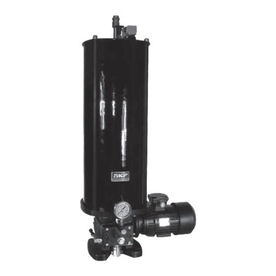
Reservoir Order No. Level monitoring If a motor-driven pump unit is not indicator capacity listed in table 1, please refer to the AS-1Q-1T05KA4+140 visual min. delivered technical sheet to know the AS-1Q-1T05KB4+140 specific technical data of the unit. visual min. + max. - Page 9 Design Page 7 motor manometer reservoir (15 kg) level switch level indicating rod max. level mark outlet ports half-cycle indicator pressure regulator filling Fig. 1 Pump AS-1Q-3R15KA4+140 filter 951-130-400, edition 04/2009...
-
Page 10: Design
Page 8 Design Design Figure 1 shows the essential design of the main piston, thus avoiding a dead point. The delivery filter (2) is protecting the system. It is motor-driven pump unit AS. located on the circuit before the changeover The lubricant reservoir is located on the pump unit. - Page 11 Design Page 9 AS pump, 30 kg reservoir AS pump, 15 kg reservoir AS pump, 5 kg reservoir Fig. 3 Dimensions of the AS pumps 951-130-400, edition 04/2009...
-
Page 12: Function
Page 10 Function Function Installation Outlet connection When the motor-driven unit is switched on, The motor-driven pump AS has to be installed The changeover block of the motor-driven the primary shaft is driving via a reduction on a horizontal surface with the reservoir pump unit has two outlets dispensing lubricant gear (1/40) a catch, which is actuating a piston pointing vertically upward. -
Page 13: Half-Cycle Indicator
Half-cycle indicator Page 11 Half-cycle indicator The motor-driven pump unit can have two different devices to indicate the good function of the half-cycle changeover. This can be a mechanical device. A rod on the side of the changeover block is indicating when the changeover has been carried out. -
Page 14: Level Monitoring
Page 12 Level monitoring Level monitoring Max. level The motor-driven pump AS can have a level switch with two different function mode according to the unit model. In both cases it is Min. level a NO + NC level switch. Minimal level The level contact switches when the minimal lubricant level has been reached and switches... -
Page 15: Adjustment Of The Flow Rate
Flow rate adjustment Page 13 Adjustment of the flow rate The motor-driven pump AS might have a flow regulator directly fitted to the pump block. Flow rate Flow rate According to the model the regulator has one cm³/min cm³/min or two adjusting screw(s). 75 cm /min 75 cm³... -
Page 16: Commissioning
Page 14 Commissioning Reservoir filling Commissioning Bleeding Before starting the motor-driven Only authorized lubricants for the Bleeding the pump pump unit check if all connections pump type may be supplied. Unsuit- • Fill the reservoir have been well mounted and tight- able lubricants could lead to the •... -
Page 17: Maintenance
The lubrication system may be under pressure. Before extension work, changes, repairs, etc. it must be depressurized. SKF motor-driven pumps AS are for the most part maintenance free. To ensure they work properly, however, please regularly check the following: •... -
Page 18: Faults
You should from reservoir without the follower plate above the follower plate. Remove the follower plate contact the SKF if the problem can not be being full and check the gasket. rectified by taking measures described here. -
Page 19: Placing Out Of Service
AS, please grease containing components. contact the SKF Service center. The system can also be taken back by SKF for disposal if the costs are covered. 951-130-400, edition 04/2009... -
Page 20: Technical Data
Page 18 Technical data Technical data Pump Level monitoring Flow rate ................. 65 cm /min Type ....................NO + NC 1,9 cm / stroke Voltage max................240 V AC Pressure max................175 bar 250 V DC Changeover pressure, adjustable Current max. -
Page 21: Service
Service Page 19 Service Please contact our sales offices or our interna- tional representatives if you have any ques- tions or problems. You can find a list with current addresses on the Internet at: • www.skf.com/lubrication 951-130-400, edition 04/2009... - Page 22 Page 20 Notes 951-130-400, edition 04/2009...
- Page 24 SKF Lubrication Systems France SAS Rue Robert Amy, B.P. 70130 49404 SAUMUR cedex FRANCE Tel. +(33) 02 41 40 42 00 • Fax+(33) 02 41 40 42 42 951-130-400-EN Edition 04/2009 www.skf.com/lubrication...
Need help?
Do you have a question about the AS-1Q-1T05KA4+140 and is the answer not in the manual?
Questions and answers