
Related Manuals for SIGMATEK S-DIAS EC 121


Summary of Contents for SIGMATEK S-DIAS EC 121
- Page 1 EC 121 S-DIAS Control Module EtherCAT Operating Manual Date of creation: 07.04.2020 Version date: 02.07.2020 Article number: 20-003-121-E...
- Page 2 (print, photocopy, microfilm or in any other process) without express permission. We reserve the right to make changes in the content without notice. SIGMATEK GmbH & Co KG is not responsible for technical or printing errors in this handbook and assumes no responsibility for damages that occur through its...
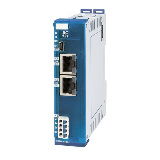
- Page 3 S-DIAS ETHERCAT CONTROL MODULE EC 121 S-DIAS Control Module EtherCAT EC 121 With 1 EtherCAT IN 1 EtherCAT Out 1 S-DIAS-Bus OUT 1 USB-Device (not used) The S-DIAS EtherCAT control module EC 121 is an interface module between an S-DIAS control system and EtherCAT bus. The module provides the voltage supply for up to 32 S-DIAS modules.
-
Page 4: Table Of Contents
EC 121 S-DIAS ETHERCAT CONTROL MODULE Contents Introduction ................6 Target Group/Purpose of this Manual ........6 Contents of Delivery ..............6 Basic Safety Guidelines ............7 Symbols Used ................7 Disclaimer ..................8 General Safety Guidelines ............9 Norms and Guidelines ............10 Guidelines.................. - Page 5 S-DIAS ETHERCAT CONTROL MODULE EC 121 6.1.2 X2: EtherCAT-IN (RJ45) ..............17 6.1.3 X3: EtherCAT-OUT (RJ45) ............... 17 Status LEDs ................. 18 Applicable Connectors ............... 19 Label Field ................... 20 Wiring Instructions ..............21 Strain Relief ................. 21 Supported S-DIAS Modules ............22 System Description ...............
- Page 6 EC 121 S-DIAS ETHERCAT CONTROL MODULE 10.3 EtherCAT Object-Specifications ..........34 10.4 Information on the EC 121 Objects ........... 35 10.4.1 Object 0x1000 Device Type ............... 35 10.4.2 Object 0x1008 Device Name ............. 35 10.4.3 Object 0x1009 Hardware Version ............36 10.4.4 Object 0x100A Software Version ............
- Page 7 S-DIAS ETHERCAT CONTROL MODULE EC 121 11.1 File system .................. 55 11.2 FoE Password ................57 11.3 File Names ................... 57 11.4 File Validation ................57 11.5 List Function ................57 11.6 Logfile ..................57 11.6.1 S-DIAS Slave ID Display ..............58 12 Update Process ..............
-
Page 8: Introduction
General knowledge of automation technology is required. Further help and training information, as well as the appropriate accessories can be found on our website www.sigmatek-automation.com Our support team is happily available to answer your questions. Please see our website for our hotline number and business hours. -
Page 9: Basic Safety Guidelines
S-DIAS ETHERCAT CONTROL MODULE EC 121 Basic Safety Guidelines Symbols Used The following symbols are used in the operator documentation for warning and danger messages, as well as informational notes: DANGER Danger indicates that death or serious injury will occur, if the specified measures are not taken. -
Page 10: Disclaimer
Please thoroughly read the corresponding data sheets, operating instruc- tions and this system handbook before handling a product. SIGMATEK GmbH & Co KG is not liable for damages caused through non-compliance with these instructions or applicable regulations. Page 8... -
Page 11: General Safety Guidelines
2006/42/EG guidelines is correct. As long as the machine with which the with the device should be used does not comply with the guide- line, operating this product is prohibited. Operate the unit with devices and accessories approved by SIGMATEK only. CAUTION Handle the device with care and do not drop or let fall. -
Page 12: Norms And Guidelines
2014/30/EU “Electromagnetic Compatibility” (EMC guideline) • 2011/65/EU “Restricted use of certain hazardous substances in electrical and electronic equipment” (RoHS Guideline) The EU Conformity Declarations are provided on the SIGMATEK website. Using the search function with the keyword “EU Declaration of Conformity”. Page 10 02.07.2020... -
Page 13: Technical Data
S-DIAS ETHERCAT CONTROL MODULE EC 121 Technical Data Performance Data Interfaces 1x EtherCAT In (RJ45) 1x EtherCAT Out (RJ45) 1x S-DIAS bus 1x USB-Device (not used) EtherCAT Specifications Configuration 2x shielded RJ45 port Cable length maximum 100 m between stations Propagation delay approximately 1 µs Potential separation... -
Page 14: Electrical Requirements
EC 121 S-DIAS ETHERCAT CONTROL MODULE Electrical Requirements Power supply +24 V +24 V DC ±20 % UL: Class 2 or LVLC Current consumption of +24 V the current consumption depends on the connected loads power supply (max. 2.75 A) Power supply on the S-DIAS bus via the EC 121 Current capacity on the S-DIAS... - Page 15 S-DIAS ETHERCAT CONTROL MODULE EC 121 02.07.2020 Page 13...
-
Page 16: Environmental Conditions
EC 121 S-DIAS ETHERCAT CONTROL MODULE Environmental Conditions Storage temperature -40 ... +85°C Environmental temperature -25 ... +60°C Humidity 0-95 %, non-condensing Installation altitude above sea 0-2000 m without derating level > 2000 m up to a maximum of 5000 m with derating of the maximum environmental temperature by 0.5 °C per 100 m Operating conditions pollution degree 2... -
Page 17: Mechanical Dimensions
S-DIAS ETHERCAT CONTROL MODULE EC 121 Mechanical Dimensions 02.07.2020 Page 15... -
Page 18: Connector Layout
EC 121 S-DIAS ETHERCAT CONTROL MODULE Connector Layout The connections of the +24 V supply (X4: pin 1 and pin 2) or the GND sup- ply (X4: pin 3 and pin 4) are internally bridged. To supply the module, only one connection to a +24 V pin (pin 1 or pin 2) and a GND pin (pin 3 or pin 4) is required. -
Page 19: Connectors
S-DIAS ETHERCAT CONTROL MODULE EC 121 Connectors 6.1.1 X1: USB-Device 2.0 (not used) Function +5 V n.c. n.c. = do not use 6.1.2 X2: EtherCAT IN (RJ45) Function Tx+/Rx+ Tx-/Rx- Rx+/Tx+ n.c. Rx-/Tx- n.c. 6.1.3 X3: EtherCAT OUT (RJ45) Function Tx - n.c. -
Page 20: Status Leds
EC 121 S-DIAS ETHERCAT CONTROL MODULE Status LEDs Sync green S-DIAS bus operating synchronously Reset S-DIAS bus in reset EC Run green Status Operational BLINKS FAST initialization or bootstrap status SINGLE Status Safe Operational FLASH FAST Pre-operational status BLINKING: Init status EC Error PDI watchdog timeout BLINKS FAST... -
Page 21: Applicable Connectors
S-DIAS ETHERCAT CONTROL MODULE EC 121 Applicable Connectors X1: USB Type Mini-B (not included in delivery) X2, X3: RJ45 (not included in delivery) X4 Connectors with spring terminals (included in delivery) The spring terminals are suitable for the connection of ultrasonically compressed (ultrasoni- cally welded) strands. -
Page 22: Label Field
EC 121 S-DIAS ETHERCAT CONTROL MODULE Label Field Manufacturer Weidmüller Type MF 10/5 CABUR MC NE WS Article number Weidmüller 1854510000 Compatible printer Weidmüller Type Printjet Advanced 230V Article number Weidmüller 1324380000 Page 20 02.07.2020... -
Page 23: Wiring Instructions
S-DIAS ETHERCAT CONTROL MODULE EC 121 Wiring Instructions Recommended Shielding Wiring the EtherCAT cables according to Ether- CAT Technology Group (ETG). Strain Relief The EtherCAT cable must be mounted close to the module (e.g. using a clamp)! No mechanical stress can be applied to the connection! 02.07.2020 Page 21... -
Page 24: Supported S-Dias Modules
EC 121 S-DIAS ETHERCAT CONTROL MODULE Supported S-DIAS Modules The S-DIAS EtherCAT control module supports the following S-DIAS modules starting from the listed serial numbers. Module name Serial number AI 022 5939502 AI 043 6060705 AI 075 6064879 AI 084 6056902 AI 088 6095866... - Page 25 S-DIAS ETHERCAT CONTROL MODULE EC 121 ICA 011 6082482 ICA 012 6096378 SI 021 5898508 SCP 011 independent 02.07.2020 Page 23...
-
Page 26: System Description
EC 121 S-DIAS ETHERCAT CONTROL MODULE System Description Architecture The S-DIAS EtherCAT Control Module functions as an EtherCAT slave and enables com- munication between an EtherCAT master and selected modules of the S-DIAS control and I/O system. Communication with up to 64 selected S-DIAS participants can be thereby implemented. -
Page 27: Initialization
S-DIAS ETHERCAT CONTROL MODULE EC 121 Initialization In the EtherCAT protocol different states and state transitions are defined during operation. The S-DIAS control module mirrors these EtherCAT states on the S-DIAS bus or in the S- DIAS slaves. 8.2.1 S-DIAS Manager EC 121 Power-Up The S-DIAS Manager integrated into the EC 121 searches the S-DIAS bus for available modules. -
Page 28: Ethercat
EC 121 S-DIAS ETHERCAT CONTROL MODULE 8.2.2 EtherCAT The following graphic shows the possible modes and mode transitions on the EtherCAT bus. 8.2.2.1 Init → PreOp • EtherCAT master reads the ID from the EEPROM. • Mailbox SyncManager (SM) is configured. •... - Page 29 S-DIAS ETHERCAT CONTROL MODULE EC 121 8.2.2.2 PreOp → SafeOp • Module list is read by the EtherCAT master. • Process data (PDO) SyncManager (SM) are configured. • Fieldbus Memory Management Units (FMMUs) are configured. • Process data mapping is written via the master. •...
-
Page 30: Initial Startup
EC 121 S-DIAS ETHERCAT CONTROL MODULE Initial Startup If the system has been configured according to the architecture description and all compo- nents have been correctly connected and linked, the S-DIAS EtherCAT interface module can be started with an EtherCAT master. Turn off the voltage supply when you want exchange or replace S-DIAS modules. -
Page 31: Manual S-Dias Configuration
S-DIAS ETHERCAT CONTROL MODULE EC 121 Manual S-DIAS Configuration Alternative to automatically loading the module configuration via the Scan instruction, the user has the option to manually define the module assignment. A double click on Box 1 (EC 121) opens the settings window for the current object. With the Slots menu, all 64 of the available module slots can be occupied. -
Page 32: Operating Mode
EC 121 S-DIAS ETHERCAT CONTROL MODULE Operating Mode The EC 121 can be operated in either in DC-Synchronous or FreeRun mode. In FreeRun mode, the EC 121 is not synchronized with EtherCAT. In this case. the module operates with a preset cycle time of 4 ms by default. This cycle time can be set via the object 0xFB10. -
Page 33: Object Directory
S-DIAS ETHERCAT CONTROL MODULE EC 121 10 Object Directory 10.1 Overview The following graphic shows an overview of the objects in the S-DIAS EtherCAT control module. 02.07.2020 Page 31... -
Page 34: S-Dias Slave Function Group Assignment
EC 121 S-DIAS ETHERCAT CONTROL MODULE 10.2 S-DIAS Slave Function Group Assignment xx = module number 0 – 63 [module at slot 5 → xx = 5] 10.2.1 TxPDO Index (TxPDO) Function Group Index (TxPDO) Function Group 0x6xx0 Digital Input 0x6xxA Status 0x6xx1... -
Page 35: Rxpdo
S-DIAS ETHERCAT CONTROL MODULE EC 121 10.2.2 RxPDO Index (RxPDO) Function Group Index (RxPDO) Function Group 0x7xx0 Digital Output 0x7xxA Config 0x7xx1 Analog Output 0x7xxB Miscellaneous 0x7xx2 0x7xxC 0x7xx3 Control word 0x7xxD 0x7xx4 0x7xxE 0x7xx5 Time offset 0x7xxF 0x7xx6 0x7xx7 0x7xx8 DriveCmd 0x7xx9... -
Page 36: Ethercat Object-Specifications
EC 121 S-DIAS ETHERCAT CONTROL MODULE 10.3 EtherCAT Object-Specifications Detailed information on the object directory for the basic structure of indi- vidual objects and the module device profile to use can be found in the corresponding EtherCAT specifications “Part 1: General MDP Device Model”, short: ETG.5001.1 S, and “Part 3: MDP Fieldbus Gateway Pro- file Specifications”, short: ETG.5001.3 S. -
Page 37: Information On The Ec 121 Objects
S-DIAS ETHERCAT CONTROL MODULE EC 121 10.4 Information on the EC 121 Objects 10.4.1 Object 0x1000 Device Type The object 0x1000 contains the type and function of the S-DIAS EtherCAT control module. The value 0x00001389 indicates a device with “Modular Device Profile”. Description Sub-Index Description / Value... -
Page 38: Object 0X1009 Hardware Version
EC 121 S-DIAS ETHERCAT CONTROL MODULE 10.4.3 Object 0x1009 Hardware Version The object 0x1009 contains the hardware version of the EC 121. Description Sub-Index Description / Value Name Hardware version Object code Data type Sub-Index 0x00 Visible String Access Sub-Index 0x00 Default value Sub-Index 0x00 10.4.4... -
Page 39: Object 0X1018 Identity Object
S-DIAS ETHERCAT CONTROL MODULE EC 121 10.4.5 Object 0x1018 Identity Object The 0x1008 contains manufacturer-specific information on the S-DIAS EtherCAT Control Module. Description Sub-Index Description / Value Name Identity Object Object code RECORD Data type Sub-Index 0x00 UNSIGNED8 Sub-Index 0x01 to 0x04 UNSIGNED32 Access Sub-Index 0x00... -
Page 40: Object 0X10F1 Error Settings
EC 121 S-DIAS ETHERCAT CONTROL MODULE 10.4.6 Object 0x10F1 Error Settings The object 0x10F1 contains EtherCAT-specific error settings. Description Sub-Index Description / Value Name Error Settings Object code RECORD Data type Sub-Index 0x00 UNSIGNED8 Sub Index 0x01 UNSIGNED32 Sub-Index 0x02 UNSIGNED16 Access Sub-Index 0x00... -
Page 41: Object 0X16Xx (Rxpdo Mapping) / Object 0X1Axx (Txpdo Mapping)
S-DIAS ETHERCAT CONTROL MODULE EC 121 10.4.7 Object 0x16xx (RxPDO Mapping) / Object 0x1Axx (TxPDO Mapping) The objects 0x16xx and 0x1Axx contain the corresponding process data mapping of the connected S-DIAS slaves. The content depends on the module configuration. 10.4.8 Object 0x1C00 Sync Manager Type The object 0x1C00 contains the type for the individual EtherCAT Sync managers. -
Page 42: Object 0X1C32/0X1C33 Sm Output/Input Parameter
EC 121 S-DIAS ETHERCAT CONTROL MODULE 10.4.10 Object 0x1C32/0x1C33 SM Output/Input Parameter These objects contain the Sync Manager Input or Output parameters. Description Sub-Index Description / Value Name SM output/input parameter Object code ARRAY Data type Sub-Index 0x00 UNSIGNED8 Sub Index 0x01 UNSIGNED16 Sub-Index 0x02 UNSIGNED32... - Page 43 S-DIAS ETHERCAT CONTROL MODULE EC 121 Function Sub-Index 0x00 Number of entries Sub Index 0x01 Sync Mode Sub-Index 0x02 Cycle Time Sub-Index 0x04 Sync modes supported Sub-Index 0x05 Minimum cycle time Sub Index 0x06 Calc and copy time Sub-Index 0x08 Get cycle time Sub-Index 0x09 Delay time...
-
Page 44: Object 0Xf000 Modular Device Profile
EC 121 S-DIAS ETHERCAT CONTROL MODULE 10.4.11 Object 0xF000 Modular Device Profile The object 0xF000 contains basic information on the modular device profile used. Description Sub-Index Description / Value Name Modular Device Profile Object code ARRAY Data type Sub-Index 0x00 UNSIGNED8 Sub Index 0x01 UNSIGNED16... -
Page 45: Object 0Xf030 Configured Module Ident List
S-DIAS ETHERCAT CONTROL MODULE EC 121 10.4.12 Object 0xF030 Configured Module Ident List The object 0xF030 contains a list of the configured S-DIAS modules with their correspond- ing module identification number. These are written by the EtherCAT Master when transi- tioning from INIT to PreOP. -
Page 46: Object 0Xf100 S-Dias Versions
EC 121 S-DIAS ETHERCAT CONTROL MODULE 10.4.14 Object 0xF100 S-DIAS Versions The object 0xF100 contains information on the S-DIAS manager Description Sub-Index Description / Value Name S-DIAS versions Object code RECORD Data type Sub-Index 0x00 UNSIGNED8 Sub-Index 0x01 to 0x02 UNSIGNED32 Sub-Index 0x03 UNSIGNED8... -
Page 47: Object 0Xf101 Ec121 Info
S-DIAS ETHERCAT CONTROL MODULE EC 121 10.4.15 Object 0xF101 EC121 Info The object 0xF101 contains the serial number of the EC 121. Description Sub-Index Description / Value Name S-DIAS versions Object code RECORD Data type Sub-Index 0x00 UNSIGNED8 Sub Index 0x01 VISIBLESTRING Access Sub-Index 0x00... -
Page 48: Object 0Xf111 Errorinfo
EC 121 S-DIAS ETHERCAT CONTROL MODULE 10.4.17 Object 0xF111 ErrorInfo The object 0xF111 contains information on errors that occurred in the system. Description Sub-Index Description / Value Name ErrorInfo Object code RECORD Data type Sub-Index 0x00 UNSIGNED8 Sub-Index 0x01 to 0x07 UNSIGNED32 Access Sub-Index 0x00... - Page 49 S-DIAS ETHERCAT CONTROL MODULE EC 121 10.4.17.1 Error Codes Error Error information Code The I/O mapping file stored in the FPGA of the slave could not be read The I/O mapping file stored in the FPGA of the slave could not be parsed The S_DIAS slave could not be detected A standard data object could not be created.
- Page 50 EC 121 S-DIAS ETHERCAT CONTROL MODULE Reading the type label failed S-DIAS module from non-supported provider Sync mode not supported Invalid serial number Page 48 02.07.2020...
- Page 51 S-DIAS ETHERCAT CONTROL MODULE EC 121 10.4.17.2 Reason Codes Rea- Error information sonCod Cause unknown Insufficient available memory File is unusable S-DIAS bus not ready S-DIAS did not confirm the state transition The S-DIAS module configuration could not be checked State transition request has failed on the S-DIAS side.
- Page 52 EC 121 S-DIAS ETHERCAT CONTROL MODULE 10.4.17.3 EtherCAT Error Codes The following table shows device-specific EtherCAT Error codes. AL Status Code Error information 0x8000 An attempt was made to start the EtherCAT state machine when the S-DIAS bus was not initialized.
-
Page 53: Object 0Xf120 S-Dias Statistics
S-DIAS ETHERCAT CONTROL MODULE EC 121 10.4.18 Object 0xF120 S-DIAS Statistics The object 0xF120 contains the statistics data for the S-DIAS bus Description Sub-Index Description / Value Name S-DIAS Statistics Object code RECORD Data type Sub-Index 0x00 UNSIGNED8 Sub-Index 0x01 to 0x04 UNSIGNED32 Access Sub-Index 0x00... -
Page 54: Object 0Xfb00 Device Control
EC 121 S-DIAS ETHERCAT CONTROL MODULE 10.4.19 Object 0xFB00 Device Control The object 0xFB00 contains control options for the EC 121 Description Sub-Index Description / Value Name Device Control Object code RECORD Data type Sub-Index 0x00 UNSIGNED8 Sub Index 0x01 UNSIGNED32 Access Sub-Index 0x00... -
Page 55: Object 0Xfb10 S-Dias Configuration
S-DIAS ETHERCAT CONTROL MODULE EC 121 10.4.20 Object 0xFB10 S-DIAS Configuration The object 0xFB10 contains the configuration options for the S-DIAS bus. Description Sub-Index Description / Value Name SDIAS Configuration Object code RECORD Data type Sub-Index 0x00 UNSIGNED8 Sub Index 0x01 UNSIGNED16 Sub-Index 0x02 UNSIGNED8... -
Page 56: Object 0X9Xx0 [Module Name] Module Information
EC 121 S-DIAS ETHERCAT CONTROL MODULE 10.4.21 Object 0x9xx0 [Module Name] Module Information The object 0x9xx0 contains general information on the respective S-DIAS module. Description Sub-Index Description / Value Name [Module Name] Module information Object code RECORD Data type Sub-Index 0x00 UNSIGNED8 Sub-Index 0x01 to 0x04 &... -
Page 57: File Handling (Foe)
S-DIAS ETHERCAT CONTROL MODULE EC 121 11 File Handling (FoE) The File Over EtherCAT (FoE) function is available in the S-DIAS EtherCAT Control Module in BOOTSTRAP mode only and is used to exchange files between the EtherCAT master and EC 121. 11.1 File system The S-DIAS EtherCAT Control Module contains its own file system in which files are stored. - Page 58 EC 121 S-DIAS ETHERCAT CONTROL MODULE The following table provides an overview of the drives and directories in the file system and which files are stored at the respective location. Drive Folder File Type Root directory Storage location for the log file foe/ Storage location for received files verified/...
-
Page 59: Foe Password
Directory traversal characters (“/“, “\“, “:“) are not allowed in the file name or are not accepted by the EC 121. The number of characters in the file name is limited to a maxi- mum of 20 characters. The name of the files provided by SIGMATEK cannot be changed when downloading to the EC 121. -
Page 60: S-Dias Slave Id Display
EC 121 S-DIAS ETHERCAT CONTROL MODULE The number of log entries is limited to 50. After the last entry, the log file is restarted from the beginning. Whereby after the newest entry, a space follows to quickly identify it. Example for Log file entries verified/AI_075_FW write verified/AI_075_FW starting slave FW update for 3ef01... -
Page 61: Update Process
S-DIAS ETHERCAT CONTROL MODULE EC 121 12 Update Process The S-DIAS EtherCAT Control Module can update its own firmware, as well as its own FPGA. In addition, the EC 121 provides the option to update the firmware and FPGA of the connected S-DIAS modules. -
Page 62: Configuration File
EC 121 S-DIAS ETHERCAT CONTROL MODULE 12.1 Configuration File The configuration file is used to update S-DIAS slaves in specified slots. If the EC 121 iden- tifies the configuration file as such, it is moved to the config folder. So that the configuration file is used during the update process, it must be stored in the file system together with the desired update file via FoE before the power cycle. -
Page 63: Providing Update Files
As previously mentioned in section 11.4, the EC 121 does not accept default update imag- es. The update images must contain a special header and a signature. The header and signature can only be added to the file by SIGMATEK. For each update type (EC 121 Firmware, EC 121 FPGA, Slave Firmware, Slave CPLD/FPGA), the corresponding update image must be requested from and/or provided by SIGMATEK. -
Page 64: Transport/Storage
EC 121 S-DIAS ETHERCAT CONTROL MODULE 13 Transport/Storage This device contains sensitive electronics. During transport and storage, high mechanical stress must therefore be avoided. For storage and transport, the same values for humidity and vibration as for operation must be maintained! During transport, temperature and humidity fluctuations may occur. -
Page 65: Mounting
S-DIAS ETHERCAT CONTROL MODULE EC 121 14 Mounting The S-DIAS modules are designed for installation into the control cabinet. To mount the modules, a DIN-rail is required. The DIN rail must establish a conductive connection with the back panel of the control cabinet. The individual S-DIAS modules are mounted on the DIN rail as a block and secured with latches. - Page 66 EC 121 S-DIAS ETHERCAT CONTROL MODULE Recommended minimum distances of the S-DIAS modules to the surrounding components or control cabinet wall: a, b, c … distances in mm (inches) Page 64 02.07.2020...
-
Page 67: Maintenance
S-DIAS ETHERCAT CONTROL MODULE EC 121 15 Maintenance During maintenance as well as servicing, observe the safety instructions from chapter 2. 15.1 Service This product was constructed for low-maintenance operation. 15.2 Repair When sent for repair, the panel should be transported in the original pack- aging if possible. - Page 68 EC 121 S-DIAS ETHERCAT CONTROL MODULE Documentation Changes Change date Affected page(s) Chapter Note 12.05.2020 4.3 Electrical requirements UL info added 4.4 Environmental Environmental temperature changed to +60 °C Conditions 28.05.2020 7.2 Supported S-DIAs Serial number added Modules 11.3 File Names Expansion added 02.07.2020 4.5 Miscellaneous...
Need help?
Do you have a question about the S-DIAS EC 121 and is the answer not in the manual?
Questions and answers