
Subscribe to Our Youtube Channel
Related Manuals for SIGMATEK ST 011


Summary of Contents for SIGMATEK ST 011
- Page 1 ST 011 S-DIAS Stepper Module Instruction Manual Date of creation: 13.02.2015 Version date: 26.07.2023 Article number: 20-014-011-E...
- Page 2 (print, photocopy, microfilm or in any other process) without the express permission. We reserve the right to make changes in the content without notice. The SIGMATEK GmbH & Co KG is not responsi- ble for technical or printing errors in the handbook and assumes no responsibility for damages that occur through...
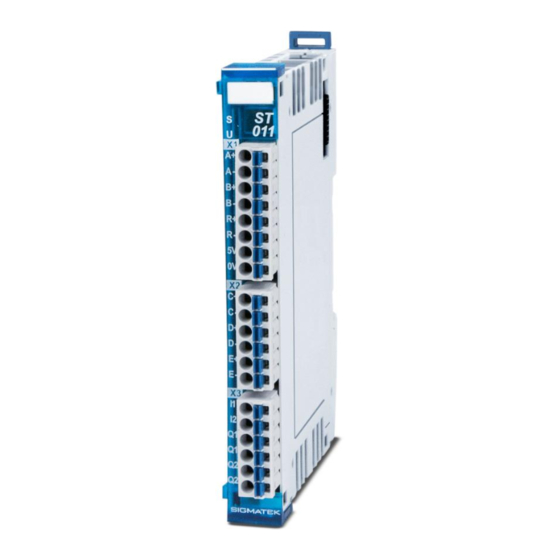
- Page 3 RS422 outputs with the appropriate signal levels. The digital inputs are provided for the reference motion and monitoring the end positions. The ST 011 also has two digital optic coupler outputs. Depending on the connector configuration, an output can be back-read (if the output high side is configured for switching).
-
Page 4: Table Of Contents
ST 011 S-DIAS STEPPER MODULE Contents Introduction ................5 Target Group/Purpose of this Operating Manual ...... 5 Important Reference Documentation ......... 5 Contents of Delivery ..............5 Basic Safety Directives ............6 Symbols Used ................6 Disclaimer ..................8 General Safety Directives ............9 Software/Training ............... - Page 5 S-DIAS STEPPER MODULE ST 011 Mechanical Dimensions ............16 Connector Layout ..............17 Status LEDs ................. 18 Applicable Connectors ............... 19 Label Field ................... 20 Wiring ..................21 Wiring Example ................21 Note ....................22 8.2.1 General ..................... 22 8.2.2 X2: Power Component Control ............
- Page 6 ST 011 S-DIAS STEPPER MODULE 12 Transport/Storage ..............32 13 Storage ...................32 14 Maintenance ................33 14.1 Service ..................33 14.2 Repair ................... 33 15 Disposal ..................33 16 Hardware Class ST011 ............34 16.1 Properties ..................35 16.2 Interfaces ..................35 16.2.1 Clients ....................35 16.2.2...
-
Page 7: Introduction
General knowledge of automation technology is required. Further help and training information, as well as the appropriate accessories can be found on our website www.sigmatek-automation.com. Our support team is happily available to answer your questions. Please see our website for our hotline number and business hours. -
Page 8: Basic Safety Directives
ST 011 S-DIAS STEPPER MODULE Basic Safety Directives Symbols Used The following symbols are used in the operator documentation for warning and danger messages, as well as informational notes: DANGER Danger indicates that death or serious injury will occur, if the speci- fied measures are not taken. - Page 9 S-DIAS STEPPER MODULE ST 011 INFORMATION Information Provides important information on the product, handling or relevant sections of the documentation, which require atten- tion. 26.07.2023 Page 7...
-
Page 10: Disclaimer
It does not guarantee properties under the warranty. Please thoroughly read the corresponding documents and this operat- ing manual before handling a product. SIGMATEK GmbH & Co KG is not liable for damages caused through, non-compliance with these instructions or applicable regulations. -
Page 11: General Safety Directives
S-DIAS STEPPER MODULE ST 011 General Safety Directives The Safety Directives in the other sections of this operating manual must be observed. These instructions are visually emphasized by symbols. INFORMATION According to EU Directives, the operating manual is a component of a product. -
Page 12: Software/Training
ST 011 S-DIAS STEPPER MODULE CAUTION Handle the device with care and do not drop or let fall. Prevent foreign bodies and fluids from entering the device. The device must not be opened! Manipulez l’appareil avec précaution et ne le laissez pas tomber. -
Page 13: Standards And Directives
The product was constructed in compliance with the following European Union directives and tested for conformity. 3.1.1 EU Conformity Declaration EU Declaration of Conformity The product ST 011 conforms to the following European directives: • 2014/35/EU Low-voltage Directive • 2014/30/EU Electromagnetic Compatibility (EMC Directive) •... -
Page 14: Type Plate
ST 011 S-DIAS STEPPER MODULE Type Plate HW: Hardware version SW: Software version Page 12 26.07.2023... -
Page 15: Technical Data
S-DIAS STEPPER MODULE ST 011 Technical Data Incremental Encoder Specifications Number Input signals Incremental encoder signals RS422 (A, /A, B, /B, R, /R) RS422 signal (150 connection, 330 spread, integrated in module) Input frequency maximum 125 kHz Counter frequency... -
Page 16: Digital Optic Coupler Specifications
ST 011 S-DIAS STEPPER MODULE Digital Optic Coupler Specifications Number Configuration potential-free (output 1 is either back readable or can be used as an input) Switching voltage maximum +30 V DC Current load maximum 100 mA Residual voltage < 2 V at 100 mA... -
Page 17: Miscellaneous
S-DIAS STEPPER MODULE ST 011 Miscellaneous Article number 20-014-011 20-014-011-X (Printed circuit board with protective lacquer) Standard UL 508 (E247993) Approbations UL, cUL, CE, UKCA Environmental Conditions Storage temperature -20 ... +85 °C Environmental temperature 0 ... +55 °C Humidity... -
Page 18: Mechanical Dimensions
ST 011 S-DIAS STEPPER MODULE Mechanical Dimensions Page 16 26.07.2023... -
Page 19: Connector Layout
S-DIAS STEPPER MODULE ST 011 Connector Layout 26.07.2023 Page 17... -
Page 20: Status Leds
ST 011 S-DIAS STEPPER MODULE Status LEDs Module Status green module active no supply available BLINKING (5 Hz) no communication User yellow can be set from the application (e.g. the module LED can be set to blinking through the visualization so that the module is easily found in the control... -
Page 21: Applicable Connectors
S-DIAS STEPPER MODULE ST 011 Applicable Connectors Connectors: X1-X3: Connectors with spring terminals (included in delivery) The spring terminals are suitable connecting ultrasonically compacted (ultrasonically weld- ed) strands. Connections: Stripping length/Sleeve length: 10 mm Plug-in direction: parallel to conductor axis or to PCB Conductor cross section, rigid: 0.2-1.5 mm... -
Page 22: Label Field
ST 011 S-DIAS STEPPER MODULE Label Field Manufacturer Weidmüller Type MF 10/5 CABUR MC NE WS Weidmüller article number 1854510000 Compatible printer Weidmüller Type Printjet Advanced 230V Weidmüller article number 1324380000 Page 20 26.07.2023... -
Page 23: Wiring
S-DIAS STEPPER MODULE ST 011 Wiring Wiring Example 26.07.2023 Page 21... -
Page 24: Note
The signal lines should be shielded or at least twisted pair wires. 8.2.2 X2: Power Component Control The ST 011 is suited for control of stepper module power components. This results in the following connection and control options. 8.2.2.1 Stepper Motor Control C+, C- (RS422) => Clock D+, D- (RS422) =>... -
Page 25: Control Variations (Rs422 Signals For The Power Component Control)
S-DIAS STEPPER MODULE ST 011 8.2.3.3 Application as Digital Input X3, pin 3 not connected (open terminal) X3, pin 4 is connected to a normal input; Output 2 can continue to be used as an optic coupler. Note: There is no status display (LED) for this digital input. -
Page 26: Incremental Encoder Rs422 Signals
ST 011 S-DIAS STEPPER MODULE 8.2.4.3 Mode 3: Pulse/Sign Command Right running Left running 8.2.5 Incremental Encoder RS422 Signals 8.2.5.1 Count UP 90° lagging 8.2.5.2 Count DOWN 90° leading Page 24 26.07.2023... -
Page 27: Latch Function
S-DIAS STEPPER MODULE ST 011 8.2.5.3 Reference pulse (zero position) 8.2.6 Latch Function This function is primarily used for the reference motion. The incremental encoder data and frequency counter values can be stored (latched) in a selected input at the time of an event. The event source (input) and event type (edge) can be set via latch registers (see address mapping for optional configurations). -
Page 28: Assembly/Installation
ST 011 S-DIAS STEPPER MODULE Assembly/Installation Check Contents of Delivery Ensure that the contents of the delivery are complete and intact. See chapter Contents of Delivery. INFORMATION On receipt and before initial use, check the device for damage. If the device is damaged, contact our customer service and do not install the device in your system. -
Page 29: Mounting
S-DIAS STEPPER MODULE ST 011 Mounting The S-DIAS modules are designed for installation into the control cabinet. To mount the modules a DIN-rail is required. The DIN rail must establish a conductive connection with the back wall of the control cabinet. The individual S-DIAS modules are mounted on the DIN rail as a block and secured with latches. - Page 30 ST 011 S-DIAS STEPPER MODULE Recommended minimum distances of the S-DIAS modules to the surrounding components or control cabinet wall: a, b, c … distances in mm (inches) Page 28 26.07.2023...
-
Page 31: Addressing
S-DIAS STEPPER MODULE ST 011 10 Addressing 10.1 Address Mapping Overview Address Size Access Description (hex) (bytes) Type PDO Write Output register 001F Bit 0: Output 1 Bit 1: Output 1 (back-readable as an input in the input register) Servo/stepper output pulse time [1 LSB = 8 ns] (-17.179 … +17.179 s) ½... - Page 32 ST 011 S-DIAS STEPPER MODULE Incremental encoder saved 003C Saves the incremental encoder counter with the result setting (memory register). 16- bit frequency counter latched 003E Saves the frequency counter value with the special event Digital Input Status Register Bit 0: input 1...
-
Page 33: Supported Cycle Times
S-DIAS STEPPER MODULE ST 011 11 Supported Cycle Times 11.1 Cycle Times below 1 ms (in µs) x= supported 11.2 Cycle Times equal to or higher than 1 ms (in ms) x= supported x= supported 26.07.2023 Page 31... -
Page 34: Transport/Storage
ST 011 S-DIAS STEPPER MODULE 12 Transport/Storage INFORMATION This device contains sensitive electronics. During transport and stor- age, high mechanical stress must therefore be avoided. For storage and transport, the same values for humidity and vibration as for operation must be maintained! Temperature and humidity fluctuations may occur during transport. -
Page 35: Maintenance
S-DIAS STEPPER MODULE ST 011 14 Maintenance INFORMATION During maintenance as well as servicing, observe the safety instruc- tions from chapter 2 Basic Safety Directives. 14.1 Service This product was constructed for low-maintenance operation. 14.2 Repair INFORMATION In the event of a defect/repair, send the device with a detailed error description to the address listed at the beginning of this document. -
Page 36: Hardware Class St011
16 Hardware Class ST011 Hardware Class ST011 for the S-DIAS ST011 stepper motor module This hardware class is used to control the ST 011 stepper motor module. More information on the hardware can be found in the module documentation. Page 34... -
Page 37: Properties
S-DIAS STEPPER MODULE ST 011 16.1 Properties 16.2 Interfaces 16.2.1 Clients The client must be connected to an S-DIAS port, an "SdiasOut"_[x]” server. SdiasIn Place The physical location of the hardware module is entered in this client. Up to 64 modules, 0 to 63, can be assigned. -
Page 38: Servers
ST 011 S-DIAS STEPPER MODULE InvertEncoder Inverts the encoder values normal inverted as initialization value InvertEnable Inverts the Enable server value normal inverted as initialization value EncoderSampling encoder off 1x analysis (rising edge) 2x analysis 4x analysis 1x analysis (falling edge) -
Page 39: Communication Interfaces
S-DIAS STEPPER MODULE ST 011 EncoderLatched This is the latched encoder value the motor. ClockCounter Frequency counter value ClockCounterLatched This server contains the latched frequency counter value. ZPuls This server is 1 when the motor is exactly on the null position. - Page 40 ST 011 S-DIAS STEPPER MODULE Documentation Changes Change date Affected Chapter Note page(s) 11.03.2015 Changed text 1.1 Incremental Encoder Changed Input signals Specifications 1.2 Power Component Con- Changed Output signals trol Output Specif. 1.3 Digital Input Specif. Changed table 4.2.2.1 Stepper Motor Control Changed text 4.2.5.3 Reference pulse...
- Page 41 S-DIAS STEPPER MODULE ST 011 26.07.2023 Document General chapters added, design 26.07.2023 Page 39...
Need help?
Do you have a question about the ST 011 and is the answer not in the manual?
Questions and answers