
Related Manuals for EUCHNER CES-I-AP-C04 Series


Summary of Contents for EUCHNER CES-I-AP-C04 Series
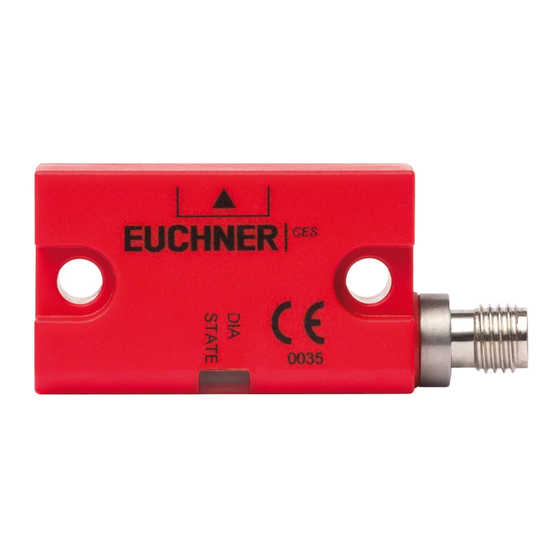
- Page 1 Operating Instructions Non-Contact Safety Switch CES-I-AP-.-C04/C14-… (Unicode/Multicode)
-
Page 2: Table Of Contents
Operating Instructions Non-Contact Safety Switch CES-I-AP-.-C04/C14-… Contents About this document ..................... 4 1.1. Scope ............................4 1.2. Target group ..........................4 1.3. Key to symbols ..........................4 1.4. Supplementary documents ......................4 Correct use ......................5 Description of the safety function ................6 Exclusion of liability and warranty ................. 6 General safety precautions ................... - Page 3 Operating Instructions Non-Contact Safety Switch CES-I-AP-.-C04/C14-… System status table CES-I-AP-… ................19 Technical data ....................20 12.1. Technical data for safety switch CES-I-AP-.-C04-… ................20 12.1.1. Dimension drawing of safety switch CES-I-AP-C04-… ............21 12.2. Technical data for safety switch CES-I-AP-.-C14-… ................22 12.2.1.
-
Page 4: About This Document
Important! Always read all documents to gain a complete overview of safe installation, setup and use of the device. The documents can be downloaded from www.euchner.com. For this purpose enter the doc. no. in the search box. (Translation of the original operating instructions) 2115159-13-03/20... -
Page 5: Correct Use
Ì EN 60204-1 The safety switch is only allowed to be operated in conjunction with the intended EUCHNER CES actuators and the related connection components from EUCHNER. On the use of different actuators or other connection components, EUCHNER provides no warranty for safe function. -
Page 6: Description Of The Safety Function
Prior to use, read the operating instructions and keep these in a safe place. Ensure the operating instructions are always available during mounting, setup and servicing. For this reason you should archive a printed copy of the operating instructions. You can download the operating instructions from www.euchner.com. (Translation of the original operating instructions) 2115159-13-03/20... -
Page 7: Function
Operating Instructions Non-Contact Safety Switch CES-I-AP-.-C04/C14-… 6. Function The safety switch monitors the position of movable guards. The safety outputs are switched on/off when the actuator is moved to/removed from the actuating range. The system consists of the following components: coded actuator (transponder) and switch. Whether the device learns the complete actuator code (unicode) or not (multicode) depends on the respective version. -
Page 8: Atex
The safety switch is allowed to be operated only in conjunction with the intended actuator CES-A-BBN-C04-EX-137527 from EUCHNER and the related connection components from EUCHNER. On the use of different actuators or other connection components, EUCHNER provides no warranty for safe function. -
Page 9: Technical Data For Housing Guard Am-C-C04-Ex-137528
Operating Instructions Non-Contact Safety Switch CES-I-AP-.-C04/C14-… Protection against mechanical effects on the switch: Ì Fit the switch on a flat surface. Install switch so that the rear of the housing is entirely covered in order to protect it from mechanical damage through impact. Ì... -
Page 10: Mounting
Operating Instructions Non-Contact Safety Switch CES-I-AP-.-C04/C14-… 8. Mounting CAUTION Safety switches must not be bypassed (bridging of contacts), turned away, removed or otherwise rendered ineffective. Ì Observe EN ISO 14119:2013, section 7, for information about reducing the possibilities for by- passing an interlocking device. NOTICE Risk of damage to equipment and malfunctions as a result of incorrect installation. - Page 11 Operating Instructions Non-Contact Safety Switch CES-I-AP-.-C04/C14-… Note the following points: Ì Actuator and safety switch must be easily accessible for inspection and replacement. Ì Actuator and safety switch must be fitted so that - the front faces are at the minimum operating distance 0.8 x S or closer when the guard is closed.
-
Page 12: Electrical Connection
Operating Instructions Non-Contact Safety Switch CES-I-AP-.-C04/C14-… 9. Electrical connection WARNING In the event of a fault, loss of the safety function due to incorrect connection. Ì To ensure safety, both safety outputs must always be evaluated. Ì Monitoring outputs must not be used as safety outputs. Ì... -
Page 13: Notes About
Use connection components and connecting cables from EUCHNER. Ì On the use of other connection components, the requirements in the following table apply. EUCHNER provides no warranty for safe function in case of failure to comply with these require- ments. Ì... -
Page 14: Connector Assignment Of Safety Switch Ces-I-Ap-.-C04
Operating Instructions Non-Contact Safety Switch CES-I-AP-.-C04/C14-… 9.5. Connector assignment of safety switch CES-I-AP-.-C04 Plug connector M12, 4-pin 5-pin S1.1 S1.1 S1.3 S1.3 S1.2 S1.2 S1.4 S1.4 n.c. S1.5 S1.5 Coding lug View of connection side on the safety switch 4-pin 5-pin 5-pin;... -
Page 15: Connection
The user is responsible for safe integration into the overall system. Detailed application examples can be found at www.euchner.com. Simply enter the order number of your switch in the search box. You will find all available connection examples for the device in Downloads. -
Page 16: Notes On Operation With Safe Control Systems
20. A detailed example of connecting and setting the parameters of the control system is available for many devices at www.euchner.com, in the area Downloads/Applications/CES. The features of the respective device are dealt with there in greater detail. -
Page 17: Setup
Operating Instructions Non-Contact Safety Switch CES-I-AP-.-C04/C14-… 10. Setup 10.1. LED displays You will find a detailed description of the signal functions in chapter 11. System status table CES-I-AP-… on page 19. CES-I-AP-.-C04-… LEDs CES-I-AP-.-C14-… Color STATE green 10.2. Teach-in function for actuator (only for unicode evaluation) The actuator must be allocated to the safety switch using a teach-in function before the system forms a functional unit. -
Page 18: Functional Check
Operating Instructions Non-Contact Safety Switch CES-I-AP-.-C04/C14-… 10.3. Functional check WARNING Danger of fatal injury as a result of faults in installation and functional check. Ì Before carrying out the functional check, make sure that there are no persons in the danger zone. Ì... -
Page 19: System Status Table Ces-I-Ap
Operating Instructions Non-Contact Safety Switch CES-I-AP-.-C04/C14-… 11. System status table CES-I-AP-… LED indicator Output Operating mode State closed Normal operation, door closed Flash burst closed Normal operation, door closed, actuator in the limit range Re-adjust door ¨ inverted Normal operation open Normal operation, door open, actuator already taught open... -
Page 20: Technical Data
Operating Instructions Non-Contact Safety Switch CES-I-AP-.-C04/C14-… 12. Technical data NOTICE If a data sheet is included with the product, the information on the data sheet applies. 12.1. Technical data for safety switch CES-I-AP-.-C04-… Parameter Value Unit min. typ. max. Housing material PBT plastic Dimensions 42 x 25 x 18... -
Page 21: Dimension Drawing Of Safety Switch Ces-I-Ap-C04
Operating Instructions Non-Contact Safety Switch CES-I-AP-.-C04/C14-… 12.1.1. Dimension drawing of safety switch CES-I-AP-C04-… Connecting cable with M12 plug connector M12x1 Connecting cable with flying lead With M8 plug connector 10,6 10,6 Active face LEDs LEDs 14,5 Active face 15,5 With rubber support Rubber support (included) 2115159-13-03/20 (Translation of the original operating instructions) -
Page 22: Technical Data For Safety Switch Ces-I-Ap-.-C14
Operating Instructions Non-Contact Safety Switch CES-I-AP-.-C04/C14-… 12.2. Technical data for safety switch CES-I-AP-.-C14-… Parameter Value Unit min. typ. max. Housing material Two-component epoxy resin Dimensions 116 x 30 x 23 Weight (device without connecting cable) Ambient temperature at U = DC 24 V + 50 °C Storage temperature... -
Page 23: Dimension Drawing Of Safety Switch Ces-I-Ap-C14
Operating Instructions Non-Contact Safety Switch CES-I-AP-.-C04/C14-… 12.2.1. Dimension drawing of safety switch CES-I-AP-C14-… 52,5 Active face LED status indication Cable end sleeves Ø8 Ø8 Ø4,6 Ø4,6 Ø8 Ø8 LED status indication Active face 2115159-13-03/20 (Translation of the original operating instructions) -
Page 24: Typical System Times
Operating Instructions Non-Contact Safety Switch CES-I-AP-.-C04/C14-… 12.3. Typical system times Refer to the technical data for the exact values. Ready delay: After switch-on, the device carries out a self-test. The system is ready for operation only after this time. Turn-on time of safety outputs: The max. reaction time t is the time from the moment when the actuator is in the actu- ating range to the moment when the safety outputs switch on. -
Page 25: Technical Data For Actuator Ces-A-Bbn-C04/Ces-A-Bbn-C04-Ex-137527
Operating Instructions Non-Contact Safety Switch CES-I-AP-.-C04/C14-… 12.4. Technical data for actuator CES-A-BBN-C04/CES-A-BBN-C04-EX-137527 Parameter Value Unit min. typ. max. Housing material PBT plastic Dimensions 42 x 25 x 18 Weight 0.03 Ambient temperature - 40 + 65 °C Degree of protection IP67/IP69K Installation position Active face opposite read head... -
Page 26: Typical Actuating Range In Installation Position A
Operating Instructions Non-Contact Safety Switch CES-I-AP-.-C04/C14-… Actuating range for center offset m = 0 (in combination with safety switch CES-C14) Installation position Parameter Value Unit min. typ. max. Operating distance 12.5 Assured operating distance s Switching hysteresis Assured release distance s 37.5 - in x/z direction 57.5... -
Page 27: Technical Data For Actuator Ces-A-Bdn-06
Operating Instructions Non-Contact Safety Switch CES-I-AP-.-C04/C14-… 12.5. Technical data for actuator CES-A-BDN-06 Parameter Value Unit min. typ. max. Housing material Macromelt PA-based plastic Dimensions 26 x ∅ 6 Weight 0.005 Ambient temperature - 40 + 70 °C Degree of protection acc. to EN IEC 60529 IP67 Installation position Active face opposite read head... -
Page 28: Technical Data For Actuator Ces-A-Bbn-161502
Operating Instructions Non-Contact Safety Switch CES-I-AP-.-C04/C14-… 12.6. Technical data for actuator CES-A-BBN-161502 Parameter Value Unit min. typ. max. Housing material PBT plastic Dimensions 42 x 25 x 12 Weight 0.025 Ambient temperature - 25 + 70 °C Degree of protection IP65/IP67 Installation position Active face opposite read head... -
Page 29: Technical Data For Actuator Ces-A-Bbn-C14-160441
Operating Instructions Non-Contact Safety Switch CES-I-AP-.-C04/C14-… 12.7. Technical data for actuator CES-A-BBN-C14-160441 Parameter Value Unit min. typ. max. Housing material Two-component epoxy resin Dimensions 72 x 30 x 17 Weight 0.04 Ambient temperature + 65 °C Degree of protection IP65/IP67/IP69/IP69K Installation position Active face opposite read head Power supply... -
Page 30: Operating Distances
Operating Instructions Non-Contact Safety Switch CES-I-AP-.-C04/C14-… 12.7.2. Operating distances Actuating range for center offset m = 0 Value Installation position Parameter Unit (ALU surroundings/PVC surroundings) min. typ. max. Operating distance 24/22 Assured operating distance s 10/11 Switching hysteresis Assured release distance s - in x/z direction - in y direction On approach in z direction... -
Page 31: Typical Actuating Range In Installation Position A
Operating Instructions Non-Contact Safety Switch CES-I-AP-.-C04/C14-… 12.7.3. Typical actuating range in installation position A (only in combination with actuator CES-A-BBN-C14-160441) - 1 0 - 1 4 - 1 8 - 2 2 - 2 6 - 3 0 - 3 4 - 3 8 - 4 2 - 4 6... -
Page 32: Ordering Information And Accessories
13. Ordering information and accessories Tip! Suitable accessories, e.g. cables or assembly material, can be found at www.euchner.com. To order, enter the order number of your item in the search box and open the item view. Accessories that can be combined with the item are listed in Accessories. -
Page 33: Declaration Of Conformity
Operating Instructions Non-Contact Safety Switch CES-I-AP-.-C04/C14-… 16. Declaration of conformity 2115159-13-03/20 (Translation of the original operating instructions) - Page 34 Operating Instructions Non-Contact Safety Switch CES-I-AP-.-C04/C14-… (Translation of the original operating instructions) 2115159-13-03/20...
- Page 35 Operating Instructions Non-Contact Safety Switch CES-I-AP-.-C04/C14-… 2115159-13-03/20 (Translation of the original operating instructions)
- Page 36 Edition: 2115159-13-03/20 Title: Operating Instructions Non-Contact Safety Switch CES-I-AP-.-C04/C14-… (Translation of the original operating instructions) Copyright: © EUCHNER GmbH + Co. KG, 03/2020 Subject to technical modifications; no responsibility is accept- ed for the accuracy of this information.
Need help?
Do you have a question about the CES-I-AP-C04 Series and is the answer not in the manual?
Questions and answers