Table of Contents
Advertisement
Advertisement
Table of Contents

Subscribe to Our Youtube Channel
Related Manuals for Emerson Control Techniques EN Series


Summary of Contents for Emerson Control Techniques EN Series
- Page 1 (217) 352-9330 | Click HERE Find the Emerson Motion Control EN-208 at our website:...
- Page 2 EN Drives Installation Manual P/N 400501-02 Revision: A5 Date: January 10, 2003 © Control Techniques Drives, Inc. 1999-2003 Artisan Technology Group - Quality Instrumentation ... Guaranteed | (888) 88-SOURCE | www.artisantg.com...
- Page 3 Artisan Technology Group - Quality Instrumentation ... Guaranteed | (888) 88-SOURCE | www.artisantg.com...
- Page 4 EN Drives Installation Manual Information furnished by Control Techniques Drives Inc. (Control Techniques) is believed to be accurate and reliable. However, no responsibility is assumed by Control Techniques for its use. Control Techniques reserves the right to change the design or operation of the equipment described herein and any associated motion products without notice.
- Page 5 Control Techniques. The following are trademarks of Control Techniques and may not be reproduced in any fashion without written approval of Control Techniques: EMERSON Motion Control, AXIMA, EMERSON Motion Control PowerTools, and “Motion Made Easy”.
- Page 6 Customer Support Control Techniques 12005 Technology Drive Eden Prairie, Minnesota 55344-3620 U.S.A. Telephone: (952) 995-8000 or (800) 397-3786 It is Control Techniques’ goal to ensure your greatest possible satisfaction with the operation of our products. We are dedicated to providing fast, friendly, and accurate assistance. That is why we offer you so many ways to get the support you need.
- Page 7 • Exact wording of any messages that appear on your screen • What you were doing when the problem occurred • How you tried to solve the problem Need on-site help? Control Techniques provides service, in most cases, the next day. Just call Control Techniques’...
- Page 8 In addition, you will find the following typographic conventions throughout this manual. This Represents Characters that you must type exactly as they appear. For example, if you are directed to type bold a:setup, you should type all the bold characters exactly as they are printed. Placeholders for information you must provide.
- Page 9 Safety Instructions General Warning Failure to follow safe installation guidelines can cause death or serious injury. The voltages used in the product can cause severe electric shock and/or burns and could be lethal. Extreme care is necessary at all times when working with or adjacent to the product. The installation must comply with all relevant safety legislation in the country of use.
- Page 10 Underwriters Laboratories Listed LISTED 51Y8 IND. CONT. EQ. The EN Digital Servo Drives are marked with the “UL Listed” label after passing a rigorous set of design and testing criteria developed by UL (UL508C). This label indicates that UL certifies this product to be safe when installed according to the installation guidelines and used within the product specifications.
- Page 11 Drive Output Current vs. Time graph % Drive Rated Current CE Declaration of Conformity The EN Digital Servo Drives are marked with the “Conformite Europeenne Mark” (CE mark) after passing a rigorous set of design and testing criteria. This label indicates that this product meets safety and noise immunity and emissions (EMC) standards when installed according to the installation guidelines and used within the product specifications.
- Page 12 Declaration of Conformity Manufacturer’s Name: Control Techniques 12005 Technology Drive Eden Prairie, MN 55344 Manufacturer’s Address: Declares that the following products: E Series Digital Servo Drive Products Description: EN-204, EN-208 and EN-214 Model Number: This declaration covers the above products with the ALP-130 Backup System Options: Logic Power Supply and ECI-44 Screw Terminal Interface.
- Page 13 Declaration of Conformity Manufacturer’s Name: Control Techniques 12005 Technology Drive Eden Prairie, MN 55344 Manufacturer’s Address: Declares that the following products: Drive Accessories Products Description: RSR-2 and ALP-430 Model Number: Conforms to the following product specification: The products herewith comply with the requirements of the Low Voltage Directive (LVD) 73/23/EEC. These products are considered components and as such, the EMC Directive (89/336/EEC) does not apply.
-
Page 14: Enclosure
EN Drive Istallation Manual Safety Considerations Safety Precautions This product is intended for professional incorporation into a complete system. If you install the product incorrectly, it may present a safety hazard. The product and system may use high voltages and currents, carry a high level of stored electrical energy, or are used to control mechanical equipment that can cause injury. - Page 15 EN Drive Istallation Manual voltages used in this unit can cause severe electric shock and/or burns, and could be lethal. Extreme care is necessary at all times when working with or adjacent to this equipment. The installation must comply with all relevant safety legislation in the country of use. AC supply isolation device The AC supply must be removed from the drive using an approved isolation device or disconnect before any servicing work is performed, other than adjustments to the settings...
-
Page 16: Table Of Contents
Table of Contents Safety Considerations Safety Precautions ............xi Enclosure . - Page 17 IP Ratings ..............52 Encoder Specifications .
-
Page 18: Introduction
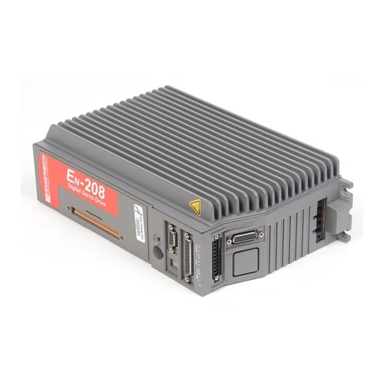
EN Drive Installation Manual Introduction EN Drives The EN drives are stand-alone, fully digital brushless servo drives designed and built to reliably provide high performance and flexibility without sacrificing ease of use. The use of State-Space algorithms make tuning very simple and forgiving. The drives are designed to operate with up to a 10 :1 inertia mismatch right out of the box. - Page 19 EN Drive Installation Manual through assignments in the software. PowerTools software is an easy-to-use Microsoft® Windows® based setup and diagnostics tool. EN Drive AC Power Input (J1) Bus Power Connection (J2) Auxiliary Power Connection (J3) Function Module Connection Drive Reset Button Analog Output Test Points Serial Communications Connection (J4) Status Display...
-
Page 20: Installation
EN Drive Installation Manual Installation Basic Installation Notes You are required to follow all safety precautions during start-up such as providing proper equipment grounding, correctly fused power and an effective Emergency Stop circuit which can immediately remove power in the case of a malfunction. See the "Safety Considerations" section for more information. - Page 21 EN Drive Installation Manual Achieving Low Impedance Connections Noise immunity can be improved and emissions reduced by making sure that all the components have a low impedance connection to the same ground point. A low impedance connection is one that conducts high frequency current with very little resistance. Impedance cannot be accurately measured with a standard ohmmeter, because an ohmmeter measures DC resistance.
- Page 22 Installation AC Line Filters The AC line filters used during Control Techniques’ compliance testing are listed below. These filters are capable of supplying the drive input power to the specified drive under maximum output power conditions. Control Techniques EN Model Schaffner Part # Rating Part #...
- Page 23 EN Drive Installation Manual Figure 2: Assembly Drawing for Shielded Cable Grommet Kits In Table Below. Cable Shielded Cable Grommet Conduit Dimension Cable Type Actual Hole Size Model Kit Model Hole Size Motor Cable, 16 Ga CMDS CGS-050 1/2" pipe 7/8"...
- Page 24 Installation Inside Enclosure Outside Enclosure O-Ring seals against outside of enclosure to meet IP 68 (comparable to NEMA 6) Spring Contacts When Lock Nut is tighten to inside of enclosure, lock nut will cut through varnished, anodized and powder coated finishes. Cable Shielding Tighten lock nut so that is cuts through finish and into housing.
- Page 25 EN Drive Installation Manual NEMA Enclosure Note: This wail must have good EMC testing was done continuity to enclosure ground. with surface paint removed from the mounting panel area AC In Through wall shield grommets for drive contact. Bonded to mounting plate and enclosure wall External Encoder Drive...
-
Page 26: Mechanical Installation
Installation Wiring Notes • To avoid problems associated with EMI (electromagnetic interference), you should route high power lines (AC input power and motor power) away from low power lines (encoder feedback, serial communications, etc.). • If a neutral wire (not the same as Earth Ground), is supplied from the building distribution panel it should never be bonded with PE wire in the enclosure. -
Page 27: Electrical Installation
EN Drive Installation Manual Electrical Installation System Grounding Enclosure Wall Ground Mains Contactor Single Point Ground 3 Phase Line Ground connection rail and enclosure panel should Power have a low impedance connection. Paint must be removed from panel mounting surface. AC Line Fuses Power Supply +24 VDC... - Page 28 Installation The Protective Earth (PE) wire connection is mandatory for human safety and proper operation. This connection must not be fused or interrupted by any means. Failure to follow proper PE wiring can cause death or serious injury. The EN-204 and EN-208 drives require 90 to 264 VAC single phase power. The EN-214 can operate with single or three phase 90 to 264 VAC.
- Page 29 EN Drive Installation Manual DISTRIBUTION PANEL SECONDARY 230 VAC To Fusing and Drive Terminals (Protective Earth) EARTH GROUND Figure 7: Earth Grounded Delta Distribution Transformer AC Supplies Requiring Transformers If the distribution transformer is configured as shown in the figures below, an isolation transformer is required.
- Page 30 Installation Figure 9: Three Phase WYE (ungrounded) Distribution to a Three-Phase Delta/WYE Isolation Transformer Figure 10: Delta to Delta Isolation Transformer Figure 11: Single Phase Power Supply Connections Artisan Technology Group - Quality Instrumentation ... Guaranteed | (888) 88-SOURCE | www.artisantg.com...
- Page 31 EN Drive Installation Manual Transformer Sizing If your application requires a transformer, use the following table for sizing the KVA rating. The values in the table are based on “worst case” power usage and can be considered a conservative recommendation. Worst case power usage assumes a motor and drive are running at the max.
-
Page 32: Input Power Connections
Installation Transformer output voltage drop may become a limiting factor at motor speeds and loads near maximum ratings. Typically, higher KVA transformers have lower voltage drop due to lower impedance. Line Fusing and Wire Size You must incorporate over current protection for the incoming AC power with the minimum rating shown here. - Page 33 EN Drive Installation Manual 50/60 Hz 90-264 VAC Front View L3 is used with the E -214 only. Note: L2 L3 GND Wire crimp ferrules are recommended: When cycling power make sure AC If 14 AWG, use panduit #PV14-P47. power is off for 5 seconds minimum If 12 AWG, use Panduit #PV10-P55.
-
Page 34: Auxiliary Logic/Alternate Power Wiring Supply
Installation Do not connect or disconnect AC power by inserting or removing the AC power connector. Using the connector in this manner, even once, will damage the connector making it unusable. Auxiliary Logic/Alternate Power Wiring Supply Auxiliary Power Supply (APS) allows the drive to retain motor position information and serial communications when the main AC power supply is disconnected. -
Page 35: Motor Power Wiring
EN Drive Installation Manual As shown in Figure 13, the auxiliary logic power connector is accessed through a plastic punch-out tab located on top of the drive that reads "BUS/AUX". The auxiliary logic power for each EN drive must be individually transformer isolated from the AC supply. The voltage range is 127 to 373 VDC, at 21 Watts. - Page 36 Installation Front View Motor Power Connection Drive Blue Black Brown Green/Yellow Ground Shield Connector Shell 2" or 3" Motors: PT06A-15-8SSR 4" Motors: MS3106A-20-15SSR Tighten screws to 5 lb-in. Wire crimp ferrules are recommended: If 14 to 16 AWG, use panduit #PV14-P47. If 12 AWG, use Panduit #PV10-P55.
-
Page 37: Motor Feedback Wiring
EN Drive Installation Manual Motor Feedback Wiring Encoder feedback connections are made with the CFCS cable. This cable has an MS style connector on the motor end and a 26-pin high density “D” connector on the drive end. +5 V Motor Feedback Cable Model # CFCS-XXX Motor... -
Page 38: Motor Brake Wiring
Installation Motor Brake Wiring Motors equipped with brakes have a three-pin MS style connector. The brake power cable (model CBMS-XXX) has an MS style connector on the motor end and three wire leads on the amplifier end (see the following wiring diagrams). You must provide a DC power supply rated at +24 VDC with a 2 amp minimum current capacity for the brake. - Page 39 EN Drive Installation Manual Figure 17: EN Brake Wiring Diagram using the I/O Connector Input/Output and Drive Enable Wiring Drives are equipped with five optically isolated input lines (one is dedicated to a drive enable function) and three optically isolated output lines. They are designed to operate from a +10 to 30 VDC source.
- Page 40 Installation Front View A highspeed diode (such as a 1N5819) is required for inductive I/O supply loads such as a relay, +10 to 30 VDC solenoid or contactor. Load Load Load 2.8 k 1 Amp Fuse Single point PE ground. 24 VDC Figure 18: EN Input/Output Wiring Diagram...
-
Page 41: Command Connector (J5) Wiring
EN Drive Installation Manual Note If loads are applied to the same output signal on both Command Connector and I/O Connector, the sum total current loading must be limited to 150 mA per output signal. Command Connector (J5) Wiring All command, 3 output and 4 input signals are available using the 44-pin Command Connector. - Page 42 Installation Shield Connected to Connector Shell Command Connector (RED/BRN) Input #1 10 Ohm (BRN/RED) Input #2 (BLK/BLU) Input #3 (BLU/BLK) Input #4 (WHT/ORG) RS 485+ (ORG/WHT) RS 485- (PRP/BLU) Encoder Output Channel A (BLU/PRP) Encoder Output Channel A/ (RED/BLU) Encoder Supply +5 Volts - Output. 200 mA (BLU/RED) Encoder Common (BLK/GRN)
- Page 43 EN Drive Installation Manual For information about Command Connector pinout and CMDO-XXX cable wire colors, see the "Specifications" section. Function Pin Numbers Electrical Characteristics Inputs and Drive Enable 1, 2, 3, 4, 16 10-30 V (“On”) 0-3 V (“Off”) optically isolated Outputs 17, 18, 19 10-30 VDC sourcing 150 mA...
- Page 44 Installation Analog Command Wiring Command Connector With positive direction = CW Figure 21: Analog Command, Differential Wiring Diagram Figure 22: Analog Command, Single Ended Wiring Diagram Artisan Technology Group - Quality Instrumentation ... Guaranteed | (888) 88-SOURCE | www.artisantg.com...
- Page 45 EN Drive Installation Manual Encoder Output Signal Wiring The encoder outputs meet RS-422 line driver specifications and can drive up to ten RS-422 signal receivers. The default encoder output scaling is set to output the actual motor encoder resolutions. The standard MG and NT motors have 2048 lines per revolution.
- Page 46 Installation Pulse Mode Wiring, Differential Inputs Single Point Panel Ground Twisted Pair Note: If the external controller does not have an internal terminating resistor R1, R2, and R3 must be mounted within 6" of the drive. A 120 ohm resistor is recommended for high frequency Single Point (over 250 kHz) feedback signals or cable lengths longer PE Ground...
- Page 47 EN Drive Installation Manual Pulse Mode Wiring, Single Ended Inputs Logic Power Direct Pulse Sinking Outputs (typ) Common isolated from other sources Figure 27: Pulse Mode, Single Ended Output to Single Ended Input (twisted pair cable) Logic Power Pulse Direct Sinking Outputs (typ) Common isolated...
- Page 48 Installation CW Pulse Logic Power CCW Pulse Sinking Outputs (typ) CW Pulse CCW Pulse Common isolated from other sources Figure 29: Pulse/Pulse Mode, Single Ended Output to Single Ended Input (non-twisted pair cable) Master Encoder or Drive Output Note: R1, R2, and R3 must be mounted within 6" of the end drive. A 120 ohm resistor is recommended for high frequency (over 250 kHz) stepping or cable lengths longer than 25 feet.
-
Page 49: Serial Communications
EN Drive Installation Manual output resolution is 2048 lines per motor revolution. This resolution is adjustable in one line per revolution increments with PowerTools software. The range is between 1 and the actual motor encoder density. Serial Communications Serial communications with the drive is provided through the female DB-9 connector located on the front of the drive. - Page 50 Installation Modbus Communications The drive’s serial communication protocol is Modbus RTU slave with a 32 bit data extension. The Modbus protocol is available on most operator interface panels and PLC’s. Serial Communications Specifications Max baud rate 19.2k Start bit Stop bit Parity none Data...
- Page 51 EN Drive Installation Manual TIA Cable DDS Cable DDS Cable TERM-T TERM-H RX (232) TX (232) 485 + Ground 485 - Computer Drive Drive Drive Serial Port Serial Port Serial Port Computer Serial Drive Serial Port Drive Serial Port Drive Serial Port Port TERM-H TERM-T...
-
Page 52: Diagnostics And Troubleshooting
EN Drive Installation Manual Diagnostics and Troubleshooting Diagnostic Display The diagnostic display on the front of the drive shows drive status and fault codes. When a fault condition occurs, the drive will display the fault code, overriding the status code. The decimal point is “On”... -
Page 53: Fault Codes
EN Drive Installation Manual Display Indication Status Description Ready to Run Drive enabled, no Stop input. Fault Codes A number of diagnostic and fault detection circuits are incorporated to protect the drive. Some faults, like high DC bus and amplifier or motor over temperature, can be reset with the Reset button on the front of the drive or the Reset input function. - Page 54 Diagnostics and Troubleshooting Display Fault Action to Reset Bridge Disabled Low DC Bus Reset Button or Input Line Encoder State Cycle Power Encoder Hardware Cycle Power Allow Motor to cool down, Motor Overtemp Reset Button or Input Line RMS Shunt Power Reset Button or Input Line (EN drives only) Overspeed...
- Page 55 EN Drive Installation Manual NVM Invalid At power-up the drive tests the integrity of the non-volatile memory. This fault is generated if the contents of the non-volatile memory are invalid. Invalid Configuration A function module was attached to the drive on its previous power-up. To clear, press and hold the Reset button for 10 seconds.
- Page 56 Diagnostics and Troubleshooting Encoder State Certain encoder states and state transitions are invalid and will cause the drive to report an encoder state fault. This is usually the result of noisy encoder feedback caused by poor shielding. For some types of custom motors it may be necessary to disable this fault. Refer to the Advanced Tab section of Setting Up Parameters for more information.
-
Page 57: Diagnostic Analog Output Test Points
EN Drive Installation Manual Travel Limit +/- This fault is caused when either the + or - Travel Limit input function is active. All "On" This is a normal condition during power up of the drive. It will last for less than 1 second. If this display persists, call Control Techniques for service advice. - Page 58 Diagnostics and Troubleshooting Channel #2 Analog GND Channel #1 Epsilon Drive E Series Drive Figure 34: Diagnostic Analog Output Test Points The DGNE cable was designed to be used with either an oscilloscope or a meter. The wires are different lengths to avoid shorting to each other. However, if signals do get shorted to GND, the drive will not be damaged because the circuitry is protected.
-
Page 59: Drive Faults
EN Drive Installation Manual Drive Faults The Active Drive Faults dialog box is automatically displayed whenever a fault occurs. There are two options in this dialog box: Reset Faults and Ignore Faults. Figure 36: Active Drive Faults Detected Dialog Box Resetting Faults Some drive faults are automatically reset when the fault condition is cleared. - Page 60 Diagnostics and Troubleshooting Note You cannot change the values of the parameters while they are being displayed in the Watch Window. The parameter in the setup screens will look like they have been changed when they actually have not. To update a parameter, delete it from the Watch Window selection.
-
Page 61: View Motor Parameters
EN Drive Installation Manual Group This list box enables you to view the complete list of parameters or just a group of parameters you are interested in. The groups include: Analog In, Analog Out, Communication, Digital Inputs, Execution, Fault Counts, Fault Log, ID, Input Functions, Motor, Output Functions, Position, Setup, Status, Torque, Tuning, User Defined Motor, and Velocity. - Page 62 Diagnostics and Troubleshooting The table below list the of common problems you might encounter when working with PowerTools software along with the error message displayed, the most likely cause and solution. Problem/Message Cause Solution Time-out while waiting for device response. Check the serial connection to the device and The attempted operation has been cancelled.
- Page 63 EN Drive Installation Manual Artisan Technology Group - Quality Instrumentation ... Guaranteed | (888) 88-SOURCE | www.artisantg.com...
-
Page 64: Specifications
EN Drive Installation Manual Specifications Drive Specifications EN Drive Specifications 90 - 264 VAC, 47-63 Hz (240 VAC for rated performance) EN-204: 1Ø AC Input Voltage: EN-208: 1Ø EN-214: 3Ø (for 1Ø operation, drive output power must be derated by 20%) EN-204: 9.5 Arms (140A for 8ms inrush) EN-208: 19 Arms (140A for 8ms inrush) AC Input Current:... - Page 65 EN Drive Installation Manual EN Drive Specifications (1) ±10 VDC 14 bit, 100 kOhm impedance, Analog Command: Differential Differential = +/- 14 VDC, each input with reference Analog Maximum Voltage to analog ground = +/- 14 VDC Input Rating: (5) 10-30 VDC, 2.8 kOhm impedance; current sourcing signal compatible (active high);...
- Page 66 Specifications EN Drive Specifications Low DC bus High DC bus Power Stage fault Logic power Encoder state Encoder line break Motor over temperature Overspeed Fault Detection Capability Travel limit (+) Travel limit (-) Pulse mode position error RMS shunt power fault Function module error Power-up self test failure Non-volatile memory invalid...
-
Page 67: Drive And Motor Combination Specifications
EN Drive Installation Manual Drive and Motor Combination Specifications Power Motor Kt Cont. Peak HP @ Inertia Encoder Motor Ke lb-in/ Torque Torque Drive Motor Rated lb-in-sec speed resolution VRMS/ ARMS lb-in lb-in Speed (kg-cm lines/rev krpm (Nm/ (Nm) (Nm) (kWatts) ARMS) 0.000094... -
Page 68: Motor Brake Specifications
Specifications Motor Brake Specifications Holding Added Inertia Added Mechanical Mechanical Torque Coil Voltage Coil Current Motor lb-in-sec2 Weight Disengagement Engagement lb-in (VDC) (Amps) (kg-cm2) lb (kg) Time Time (Nm) NTE/M-2XX 0.000106 -CBNS, -LBNS, 24 (±10%) 0.33 (±10%) 28 ms 14 ms (2.26) (0.12) (0.46) -
Page 69: Axial/Radial Loading
EN Drive Installation Manual Axial/Radial Loading Max Radial Max. Axial Motor Load (lb.) Load (lb.) NTE/M-207 NTE/M-212 NTE/M-320 NTE/M-330 NTE/M-345 NTE/M-355 MGE-205 MGE-208 MGE-316 MGM-340 MGE/M-455 MGE/M-490 MGE/M-4120 Figure 40: Axial/Radial Loading IP Ratings Motor Rating MG (all) IP65 NTE/M-207 IP65 NTE/M-207 (w/o seals) IP54... -
Page 70: Encoder Specifications
Specifications Encoder Specifications Motor Density Output Type Output Frequency Output Signals Power Supply A, B, Z, Comm U, RS422 differential MG and NT 2048 lines/rev 250 kHz per channel Comm W, Comm V 5V, 200 mA ±10% driver and all complements Power Dissipation In general, the drive power stages are 90 to 95 percent efficient depending on the actual point of the torque speed curve the drive is operating. - Page 71 EN Drive Installation Manual Power Dissipation Calculation Calculating actual dissipation requirements in an application can help minimize enclosure cooling requirements, especially in multi-axis systems. To calculate dissipation in a specific application, use the following formula for each axis and then total them up. This formula is a generalization and will result in a conservative estimate for power losses.
-
Page 72: Speed Torque Curves
Specifications Speed Torque Curves Continuous ratings of the MG and NT motors are based on 100°C (212°F) motor case temperature and 25°C (77°F) ambient temperature with the motor mounted to an aluminum mounting plate as shown in the table below Motor Mounting Plate Size MG-205 and 208, NT-207 and 212... - Page 73 EN Drive Installation Manual Artisan Technology Group - Quality Instrumentation ... Guaranteed | (888) 88-SOURCE | www.artisantg.com...
- Page 74 Specifications Artisan Technology Group - Quality Instrumentation ... Guaranteed | (888) 88-SOURCE | www.artisantg.com...
- Page 75 EN Drive Installation Manual NT-330 with EN-208 NT-320 with EN-208 4500 4500 4000 4000 3500 3500 120 VAC 120 VAC 3000 3000 2500 2500 2000 2000 1500 1500 1000 1000 Peak Continuous Continuous Peak Rating Rating Rating Rating lb-in lb-in 0.56 1.13 1.69...
-
Page 76: En Drive Dimensions
Specifications EN Drive Dimensions Minimum Connector Clearance if used "A" 6.90 0.39 [175.24] 1.75 [9.78] 1.85 [44.57] 0.41 [47.12] 0.33 [10.49] [8.32] 11.20 11.70 [284.54] [297.08] 0.41 [10.37] 0.20 (5.08) Typ. 4 Places Model Dim “A” EN-204 2.93 [74.4] EN-208 3.43 [87.1] EN-214 3.93 [99.8]... -
Page 77: Mg Motor Dimensions
EN Drive Installation Manual MG Motor Dimensions MGE-205 and 208 Motors MGE-205 and 208 Mounting Dimensions inches (mm) U Max S Min C Max 5.60 2.25 0.46 1.20 0.375 0.563 0.127 0.300 2.625 0.063 1.502 0.205 (143.0) (57.2) (11.2) (30.5) (9.525) (14.3) (3.23) - Page 78 Specifications MGE-455, 490 and 4120 Motors MGE-455, 490 and 4120 Mounting Dimensions inches (mm) U Max S Min C Max 8.61 5.00 0.53 0.6245 1.50 0.1875 0.51 3.20 5.875 0.10 4.500 3/8-16 (218.7) (127.0) (13.5) (48.2) (15.862) (38.1) (4.763) (13.0) (81.3) (149.23) (2.50)
-
Page 79: Nt Motor Dimensions
EN Drive Installation Manual NT Motor Dimensions NTE-207 and 212 Motors; English Face (NEMA 23 with 3/8 inch shaft) 1.780 [45.21] ENCODER CONN: PT02E-16-23P MATING CONN: PT06E-16-23S (-CONS) MOTOR CONN: PT02E-16-8P MATING CONN: PT06E-16-8S DRILLED (-CONS) THRU (4) EQUALLY SPACED ON 1.925 [48.89] NTE-207, 212 -CONS,TONS and LONS Mounting Dimensions inches (mm) - Page 80 Specifications NTM-207 and 212 Motors; Metric Face 1.780 [45.21] ENCODER CONN: PT02E-16-23P MATING CONN: PT06E-16-23S (-CONS) MOTOR CONN: PT02E-16-8P MATING CONN: PT06E-16-8S DRILLED (-CONS) THRU (4) EQUALLY SPACED ON 1.925 [48.89] NTM-207, 212 -CONS,TONS and LONS Mounting Dimensions mm (inches) 140.96 65.18 7.49...
- Page 81 EN Drive Installation Manual NTE-207 and 212 Brake Motors; English Face (NEMA 23 with 3/8 inch shaft) MOTOR CONN: PT02E-16-8P MATING CONN: PT06E-16-8S (-TBNS) FLYING LEAD LENGTH: 39.37±2.00 [1000±50.8] (-LBNS and -TBNS) ENCODER CONN: PT02E-16-23P MATING CONN: PT06E-16-23S (-TBNS) BRAKE CONN: PT02E-8-3P MATING CONN: PT06E-8-3S (-TBNS) ENCODER CONN: PT02E-16-23P...
- Page 82 Specifications NTE-207 and 212 Brake Motors; Metric Face 159, MOTOR CONN: PT02E-16-8P MATING CONN: PT06E-16-8S (-TBNS) FLYING LEAD LENGTH: 39.37±2.00 [1000±50.8] (-LBNS and -TBNS) ENCODER CONN: PT02E-16-23P MATING CONN: PT06E-16-23S (-TBNS) BRAKE CONN: PT02E-8-3P MATING CONN: PT06E-8-3S (-TBNS) ENCODER CONN: PT02E-16-23P MATING CONN: PT06E-16-23S (-CBNS) BRAKE CONN: PT02E-8-3P MATING CONN: PT06E-8-3S (-CBNS)
- Page 83 EN Drive Installation Manual NTE/M-320, 330, 345 and 355 Motors FLYING LEAD LENGTH: 39.37±2.00 [1000±50.8] (-LONS and -TONS) 2.35 [59.69] MOTOR CONN: PT02E-16-8P ENCODER CONN: PT02E-16-23P MATING CONN: PT06E-16-8S MATING CONN: PT06E-16-23S (-CONS) (-CONS) DRILLED THRU (4) EQUALLY SPACED ON 2.450 [62.24] 45°...
-
Page 84: Motor Wiring Color Cable
Specifications Motor Wiring Color Cable Motor Encoder Motor Cable Motor Cable Motor Encoder CFCO Cable Connector Pin # Signal Name Colors Colors Cable Colors (CONS/TONS) (Current) (Previous) Blue Blue Blue Orange Blue/White Orange Green Green Green Brown Green/White Brown Black Yellow Black Yellow... -
Page 85: Cable Diagrams
EN Drive Installation Manual Motor Power Connector: PT02E-16-8P Encoder Connector: PT02E-16-23P Mating Connector: PT06E-16-8S Mating Connector: PT06E-16-23S Cable Diagrams Drive Signal CMDX, CMDO, ECI-44 CDRO AX4-CEN Analog Command In + Analog Command In - Encoder Out A Encoder Out A/ Encoder Out B Encoder Out B/ Encoder Out Z... - Page 86 Specifications Drive Signal CMDX, CMDO, ECI-44 CDRO AX4-CEN I/O Power + In (1st wire) I/O Power + In (2nd wire) I/O Power 0V In (1st wire) I/O Power 0V In (2nd wire) Analog Out 0V Analog Out Channel #1 + Analog Out Channel #2 + External Encoder +5 Power Out (200 ma) External Encoder Common...
- Page 87 EN Drive Installation Manual CMDX-XXX Cable FUNCTION COLOR CODE RED/BROWN STRIPE INPUT I/O 1 BROWN/RED STRIPE INPUT I/O 2 INPUT I/O 3 BLACK/BLUE STRIPE BLUE/BLACK STRIPE INPUT I/O 4 WHITE/ORANGE STRIPE RS-485+ RS-485- ORANGE/WHITE STRIPE PURPLE/BLUE STRIPE* MOTOR ENCODER OUTPUT A BLUE/PURPLE STRIPE* MOTOR ENCODER OUTPUT A/ EXT ENCODER 200mA max +5V...
- Page 88 Specifications CMDO-XXX Cable PIN 1 2.10 COLOR CODE FUNCTION INPUT I/O 1 RED/BROWN STRIPE BROWN/RED STRIPE INPUT I/O 2 INPUT I/O 3 BLACK/BLUE STRIPE BLUE/BLACK STRIPE INPUT I/O 4 RS-485+ WHITE/ORANGE STRIPE ORANGE/WHITE STRIPE RS-485- PURPLE/BLUE STRIPE* MOTOR ENCODER OUTPUT A BLUE/PURPLE STRIPE* MOTOR ENCODER OUTPUT A/ RED/BLUE STRIPE...
- Page 89 EN Drive Installation Manual CDRO-XXX Cable PIN 1 WIRE COLOR SOLID/STRIPE BLU/PUR ENCODER OUTPUT A/ PUR/BLU ENCODER OUTPUT A ORG/PUR ENCODER OUTPUT B/ PUR/ORG ENCODER OUTPUT B BRN/PUR ENCODER OUTPUT Z/ PUR/BRN ENCODER OUTPUT Z RED/BLU ENCODER +5VDC SUPPLY BLU/RED ENCODER SUPPLY COMMON GRN/BLK I/O SUPPLY +...
- Page 90 Specifications AX4-CEN-XXX Cable BLU/PUR ENCODER OUTPUT A/ ENCODER OUTPUT A/ PUR/BLU ENCODER OUTPUT A ENCODER OUTPUT A ORG/PUR ENCODER OUTPUT B/ ENCODER OUTPUT B/ PUR/ORG ENCODER OUTPUT B ENCODER OUTPUT B BRN/PUR ENCODER OUTPUT Z/ ENCODER OUTPUT Z/ PUR/BRN ENCODER OUTPUT Z ENCODER OUTPUT Z RED/BLU BLU/RED...
- Page 91 EN Drive Installation Manual TIA-XXX Cable PIN 1 2.5 MAX (2X) PIN 1 0.250 .63 MAX (2X) END VIEW FEMALE END VIEW (SOCKETS) MALE (PINS) BLACK WHITE BLUE BRAID + DRAIN SHELL SHELL MALE DB-9 CONN FEMALE DB-9 CONN DDS-XXX Cable SHELL DB-9 MALE DRAIN...
- Page 92 Specifications TERM-H (Head) Terminator 1.22 R.195 TERM-H PIN #1 .110 MAX (2) .67 REF .090 MIN R1 IN (RX) T1 OUT (TX) 485+ 485- NOT USED NOT USED NOT USED SHELL SHELL DB-9 MALE DB-9 FEMALE TERM-T (Tail) Terminator 1.22 R.195 PIN #1 .110 MAX (2)
- Page 93 EN Drive Installation Manual CMDS-XXX Cable 3.23 1.20 3.0 +/- 0.25 GRN/YEL SHELL SOLDER SIDE CMMS-XXX Cable 3.99 1.40 3.0 +/- 0.25 GRN/YEL SHELL SOLDER SIDE Artisan Technology Group - Quality Instrumentation ... Guaranteed | (888) 88-SOURCE | www.artisantg.com...
- Page 94 Specifications CFCS-XXX Cable 2.24 3.16 1.18 1.55 OVERALL TIN/COPPER BRAID SHELL WHT/BRN WHT/BRN BRN/WHT BRN/WHT WHT/GRY WHT/GRY GRY/WHT GRY/WHT RED/ORN RED/ORN ORN/RED ORN/RED LARGE 18GA PAIR RED/GRN OR RED/BLU 7 RED/BLU +5 VDC BLU/RED BLU/RED RED/GRN RED/GRN MOTOR OVERTEMP GRN/RED GRN/RED NOT USED 18 N/C...
- Page 95 EN Drive Installation Manual CFCO-XXX Cable 2.24 PIN 1 1.55 PLUGGING SIDE OVERALL T/C BRAID WHT/BRN BRN/WHT WHT/GRAY GRAY/WHT RED/ORN ORN/RED RED/BLU RED/GRN OR LARGE 18 GA PAIR BLU/RED RED/GRN GRN/RED = TWISTED PAIR CONNECTOR SHELL PIN 1 SOLDER SIDE Artisan Technology Group - Quality Instrumentation ...
- Page 96 Specifications CFOS-XXX Cable 3.16 1.18 OVERALL TIN/COPPER BRAID SHELL WHT/BRN BRN/WHT WHT/GRY GRY/WHT RED/ORN ORN/RED LARGE 18GA PAIR RED/GRN OR RED/BLU BLU/RED RED/GRN GRN/RED = TWISTED PAIR DRAINS SOLDER SIDE Artisan Technology Group - Quality Instrumentation ... Guaranteed | (888) 88-SOURCE | www.artisantg.com...
- Page 97 EN Drive Installation Manual Artisan Technology Group - Quality Instrumentation ... Guaranteed | (888) 88-SOURCE | www.artisantg.com...
-
Page 98: Glossary
Epsilon Eb and EN Drives Reference Manual Glossary µs Microsecond. Amps. ARMS Amps (RMS). American Wire Gauge. Baud Rate The number of binary bits transmitted per second on a serial communications link such as RS- 232. (1 character is usually 10 bits.) Check Box In a dialog box, a check box is a small box that the user can turn “On”... - Page 99 Epsilon Eb and EN Drives Reference Manual Downloading The transfer of a complete set of parameters from PowerTools or an FM-P. EEPROM An EEPROM chip is an Electrically Erasable Programmable Read-Only Memory; that is, its contents can be both recorded and erased by electrical signals, but they do not go blank when power is removed.
- Page 100 Glossary Input Line The actual electrical input, a screw terminal. Least Significant Bit The bit in a binary number that is the least important or having the least weight. Light Emitting Diode. List Box In a dialog box, a list box is an area in which the user can choose among a list of items, such as files, directories, printers or the like.
- Page 101 Epsilon Eb and EN Drives Reference Manual Output Function A function (i.e., Drive OK, Fault) that may be attached to an output line. Output Line The actual transistor or relay controlled output signal. Parameters User read only or read/write parameters that indicate and control the drive operation. Protective Earth.
- Page 102 Glossary Revolutions Per Minute. Serial Port A digital data communications port configured with a minimum number of signal lines. This is achieved by passing binary information signals as a time series of 1’s and Ø’s on a single line. Uploading The transfer of a complete set of parameters from PowerTools or an FM-P.
- Page 103 Epsilon Eb and EN Drives Reference Manual Artisan Technology Group - Quality Instrumentation ... Guaranteed | (888) 88-SOURCE | www.artisantg.com...
-
Page 104: Index
Epsilon Eb and EN Drives Reference Manual Index Diagnostic Cable (DGNE) Diagram, 41 Diagnostic Display, 35 Diagnostics and Troubleshooting, 35 AC Line Filter Installation Notes, 5 Drive and Motor Combination AC Line Filters, 5 Specifications, 50 AC Supplies NOT Requiring Drive Enable Wiring, 22 Transformers, 11 Drive Faults, 42... - Page 105 Epsilon Eb and EN Drives Reference Manual Input/Output, 22 Installation, 3 Installation Notes, 3 Power Dissipation, 53 Introduction, 1 Power Dissipation Calculation, 54 IP Ratings, 52 Pulse Mode Wiring, 29 Line Fusing, 15 Rebooting the Drive, 42 Resetting Faults, 42 Mechanical Installation, 9 MG Motor Dimensions, 60 Safety Considerations, xi...
- Page 106 Index Vendor Contact Information, 79 View Motor Parameters, 44 Viewing Active Drive Faults, 42 Watch Window, 42 Wire Size, 15 Wiring Notes, 9 Artisan Technology Group - Quality Instrumentation ... Guaranteed | (888) 88-SOURCE | www.artisantg.com...
- Page 107 Epsilon Eb and EN Drives Reference Manual Artisan Technology Group - Quality Instrumentation ... Guaranteed | (888) 88-SOURCE | www.artisantg.com...
- Page 108 Artisan Technology Group - Quality Instrumentation ... Guaranteed | (888) 88-SOURCE | www.artisantg.com...
- Page 109 For more information about Control Techniques “Motion Made Easy” products and services, call (800) 397-3786 or contact our website at www.emersonct.com. Control Techniques Drives, Inc Division of EMERSON Co. 12005 Technology Drive Eden Prairie, Minnesota 55344 U.S.A. Customer Service...
Need help?
Do you have a question about the Control Techniques EN Series and is the answer not in the manual?
Questions and answers