Table of Contents
Advertisement
Quick Links
F
u
n
c
F
u
n
c
F
u
n
c
25 MHz - - - -
25 MHz
25 MHz
25 MHz
5 5 5 5
0 0 0 0
M M M M
5 5 5 5
0 0 0 0
M M M M
5 5 5 5
0 0 0 0
M M M M
Copyright ©
t
i
o
n
/
A
t
i
o
n
/
A
t
i
o
n
/
A
W
W
W
G
e
G
e
G
e
G G G G
G G G G
G G G G
H H H H
z z z z
- - - -
G G G G
H H H H
z z z z
- - - -
G G G G
H H H H
z z z z
- - - -
G G G G
U
s
e
r
'
s
m
a
U
s
e
r
'
s
m
U
s
e
r
'
s
m
Pôle Test et Mesure de CHAUVIN-ARNOUX
Parc des Glaisins - 6, avenue du Pré de Challes
Tel. +33 (0)4.50.64.22.22 - Fax +33 (0)4.50.64.22.00
r
b
i
t
r
b
i
t
r
b
i
t
a
v
e
f
a
v
e
f
a
v
e
f
n
e
r
a
n
e
r
a
n
e
r
a
X X X X
1 1 1 1
0 0 0 0
X X X X
1 1 1 1
0 0 0 0
X X X X
1 1 1 1
0 0 0 0
X X X X
1 1 1 1
0 0 0 0
X X X X
1 1 1 1
0 0 0 0
X X X X
1 1 1 1
0 0 0 0
n
u
a
l
a
n
u
a
l
a
n
u
a
l
F - 74940 ANNECY-LE-VIEUX
X03739A00 - Ed. 01 - 10/11
r
a
r
y
r
a
r
y
r
a
r
y
o
r
m
o
r
m
o
r
m
t
o
r
s
t
o
r
s
t
o
r
s
2 2 2 2
5 5 5 5
2 2 2 2
5 5 5 5
2 2 2 2
5 5 5 5
5 5 5 5
0 0 0 0
5 5 5 5
0 0 0 0
5 5 5 5
0 0 0 0
Advertisement
Table of Contents

Subscribe to Our Youtube Channel
Related Manuals for Metrix GX 1025


Summary of Contents for Metrix GX 1025
- Page 1 G G G G X X X X 1 1 1 1 0 0 0 0 2 2 2 2 5 5 5 5 G G G G X X X X 1 1 1 1 0 0 0 0 2 2 2 2 5 5 5 5 25 MHz - - - -...
-
Page 2: Table Of Contents
General Instructions Contents General Instructions ............................. 3 Introduction, Precautions, Safety, Environment ....................3 Guarantee, Maintenance, Metrological verification, Cleaning ................4 r II Instrument Description ............................5 Introduction................................. 5 Front panel, rear panel, handle .......................... 6 Display Interface..............................7 Getting Started ..............................9 1. -
Page 3: General Instructions
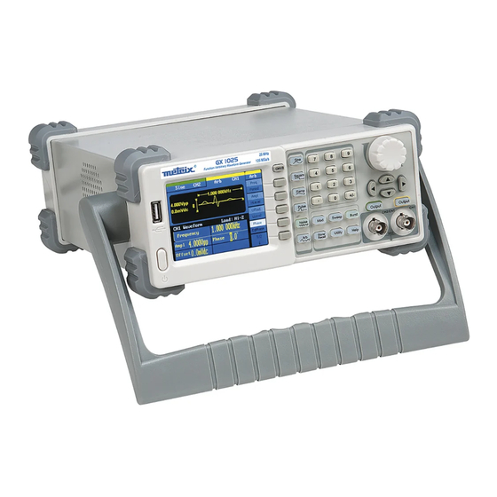
General Instructions General Instructions Introduction You have just purchased a GX 1025 or GX 1050 Function / Arbitrary Waveform Generator and we appreciate your confidence. Precautions To obtain the best service: - read this notice carefully, - respect the safety instructions. -
Page 4: Guarantee, Maintenance, Metrological Verification, Cleaning
General Instructions General Instructions (contd.) Overvoltage category ll is for equipment intended to be supplied from the Definition of building wiring. It applies both to plug-connected equipment and to measurement categories permanently connected equipment. Overvoltage category lll is for equipment intended to form part of a building wiring installation. -
Page 5: Instrument Description
• 3.5’ TFT color LCD display. • 125 MSa/s sampling rate, 14-bit resolution. • Frequency characteristics: GX 1025 GX 1050 Sine 1 µHz to 25 MHz 1 µHz to 50 MHz Square 1 µHz to 25 MHz 1 µHz to 25 MHz Ramp 1 µHz to 300 kHz... -
Page 6: Front Panel, Rear Panel, Handle
Description of the instrument Description of the instrument (contd.) Front panel Rear panel 10MHz In Sync Out Device Ext Trig/Gate/ Power Fsk/Burst Modulation Socket The external input voltage can’t be over 12 Vpp, otherwise instrument gets damaged. II - 6 Function/Arbitrary Waveform Generators... - Page 7 Description of the instrument Description of the instrument (contd.) Handle Adjustment To adjust the handle position of the Function/Arbitrary Waveform Generator, please grip the handle by the sides and pull it outward. Then, make the handle rotate to the desired position. Viewing Position and Carrying Position : Function/Arbitrary Waveform Generators II - 7...
-
Page 8: Display Interface
Description of the instrument Description of the instrument (contd.) Sine Wave is the default display signal : Display Interface Waveform Display Operation Menu: Window Different functions have different menus Parameter Display and Editing Window II - 8 Function/Arbitrary Waveform Generators... -
Page 9: Getting Started
Sine and the waveform window will display sine waveform. The generator can generate sine signal with a frequency from 1µHz to 25 MHz (GX 1025), or 50 MHz (GX 1050). By setting frequency/period, amplitude/high level, offset/low level, sine signal with different parameters can be generated. - Page 10 Getting Started Getting Started (contd.) (contd.) 1. To set a waveform Step 2 Press Square and the waveform window displays square waveform. The generator can generate square signal with a frequency from 1µHz to 25MHz and variable duty cycle. A shown, the default signal parameters are: 1 kHz frequency, 4.0 Vpp amplitude, 0 Vdc offset and 50% duty cycle.
- Page 11 Getting Started Getting Started (contd.) (contd.) 1. To set a waveform Step 4 Press Pulse button, and the waveform window displays pulse waveform. The generator can generate pulse signal with a frequency from 500 µHz to 5 MHz and variable pulse width and delay. As shown, the default signal parameters are: 1 kHz frequency, 4.0 Vpp amplitude, 0 Vdc offset, 200 µs pulse width.
- Page 12 Getting Started Getting Started (contd.) (contd.) 1. To set a waveform Step 6 Press Arb button, and the waveform window displays arbitrary waveform. The generator can generate repeatable arbitrary waveform signals with at most 16 K points and 5 MHz frequency. As shown, the default sine signal parameters are: 1 kHz frequency, 4.0 Vpp amplitude and 0mVdc offset.
-
Page 13: To Set Modulate / Sweep / Burst
Getting Started Getting Started (contd.) 2. To set Modulate / : those three buttons on the front panel are used for Sweep / Burst modulation, sweep and burst settings. The instructions below will help you familiarize with the setting of these functions. Step 1 Press Mod button, and the modulated waveforms will be generated. -
Page 14: To Set Output
Getting Started Getting Started (contd.) (contd.) 2. To set Modulate / Sweep / Burst Step 3 Press Burst button, burst for sine, square, ramp, pulse or arbitrary waveform can be generated. Term Explanation Output waveforms with set cycle times. Burst Burst can last for certain times of waveform cycle (N-Cycle Burst) or be controlled by external gated signals (Gated Burst). -
Page 15: To Use Digital Input
Getting Started Getting Started (contd.) As shown below, there are three sets of buttons on the operation panel, 4. To use Digital Input which are direction button, the knob and the keypad. The instruction below will help you familiarize with the digital input function. 1. -
Page 16: Functional Descroption
Functional Description Functional Description 1. To Set Sine Signals Press this button to call the sine operation. The sine waveform parameters are set by using the sine operation menu. The parameters of sine waveforms are : • frequency/period • amplitude/high level •... - Page 17 Functional Description Functional Description (contd.) To Set the Output Frequency/Period 1. Press Sine →Freq, to set the frequency parameter. The frequency shown on the screen when the instrument is powered is the default value or the set value beforehand. When setting the function, if the current value is valid for the new waveform, it will be used sequentially.
- Page 18 Functional Description Functional Description (contd.) To Set the Output Amplitude 1. Press Sine →Ampl , to set the amplitude. The amplitude shown on the screen when the instrument is powered is the default value or the set value beforehand. When changing the function, if the current value is valid for the new waveform, it will be used sequentially.
- Page 19 Functional Description Functional Description (contd.) To Set the DC Offset Press Sine →Offset , to set the offset. The offset shown on the screen when the instrument is powered is the default value or the set value beforehand. When changing the function, if the current value is valid for the new waveform, it will be used sequentially.
-
Page 20: To Set Ramp Signals
Functional Description Functional Description (contd.) 2. To Set Square Signals Press this button to call the Square operation. The square waveform parameters are set by using the Square operation menu. The parameters of Square waveforms are: frequency/period, amplitude/high level, offset/low level, phase and duty cycle. As is shown below, in the soft key menu, select Duty. - Page 21 Functional Description Functional Description (contd.) To Set the Duty Cycle 1. Press Square → Duty , to set the duty cycle. The duty cycle shown on the screen when the instrument is powered is the default value or the set value beforehand. When changing the function, if the current value is valid for the new waveform, it will be used sequentially.
-
Page 22: To Set Square Signals
Functional Description Functional Description (contd.) 3. To Set Ramp Signals Press this button to call the ramp operation. The ramp waveform parameters are set by using the ramp operation menu. The parameters for ramp waveforms are: frequency/ period, amplitude/ high level, offset/ low level, phase and symmetry. - Page 23 Functional Description Functional Description (contd.) To Set the Symmetry 1. Press Ramp → Symmetry , to set the symmetry. The symmetry shown on the screen when the instrument is powered is the default value or the set value beforehand. When changing the function, if the current value is valid for the new waveform, it will be used sequentially.
-
Page 24: To Set Pulse Signals
Functional Description Functional Description (contd.) 4. To Set Pulse Signals Press this button to call the pulse operation. The pulse waveform parameters are set by using the pulse operation menu. The parameters for pulse waveforms are: frequency/period, amplitude/high level, offset/low level, pulse width and delay. As is shown below, in the soft key menu, select PulWidth. - Page 25 Functional Description Functional Description (contd.) To Set the Pulse Width 1. Press Pluse → PulWidth, to set the pulse width. The pulse width shown on the screen when the instrument is powered is the default value or the set value beforehand. When changing the function, if the current value is valid for the new waveform, it will be used sequentially.
- Page 26 Functional Description Functional Description (contd.) To Set the Delay 1. Press Pulse → Delay, to set the delay. The delay shown on the screen when the instrument is powered is the default value or the set value beforehand. When changing the function, if the current value is valid for the new waveform, it will be used sequentially.
-
Page 27: To Set Noise Signals
Functional Description Functional Description (contd.) 5. To Set Noise Signals Press this button to call the gaussian white noise operation. The noise waveform parameters are set by using the noise operation menu. The parameters for noise waveforms are: amplitude/high level and offset/low level. -
Page 28: To Set Arbitrary Signals
Functional Description Functional Description (contd.) 6. To Set Arbitrary Signals Press this button to call the arb operation. The arb waveform parameters are set by using the arb operation menu. The arb signal consists of two types: the system built-in waveform and the user-definable waveform. - Page 29 Functional Description Functional Description (contd.) 6. To Set Arbitrary Signals (contd.) Menu Explanations of Arb Waveform Function Explanation Menu Select the built-in arbitrary signal as output. Load Wform To Select the built-in Arbitrary Waveform There are forty-eight built-in Arbitrary Waveforms and user-definable Arbitrary Waveforms inside the Generator.
- Page 30 Functional Description Functional Description (contd.) a) To Select the Built-in Waveform Press Arb → Load Wform->Built-In , and enter the following interface. Function Explanation Menu Common Select common waveform. Math Select math waveform. Project Select project waveform. Winfun/ Select windows function. Triangle /triangle waveform.
- Page 31 Functional Description Functional Description (contd.) Math Built-In Arbitrary Waveform Interface Menu Explanations of Function Explanation Math Built-in Arbitrary Menu Waveform ExpFall Select the built-in exponential fall waveform. ExpRise Select he built-in exponential rise waveform. LogFall Select the built-in logarithmic fall waveform. LogRise Select the built-in logarithmic rise waveform.
- Page 32 Functional Description Functional Description (contd.) Project Built-In Arbitrary Waveform interface Menu Explanations of Function Explanation Project Built-in Menu Arbitrary Waveform Select the built-in electrocardiogram (ECG) signal Cardiac waveform. Quake Select the built-in loma prieta earthquake waveform. Chirp Select the built-in swept-frequency cosine waveform. TwoTone Select the built-in two tone signal waveform Select the built-in sin wave with white noise waveform.
- Page 33 Functional Description Functional Description (contd.) Winfun/Triangle Built- In Arbitrary Waveform interface Menu Explanations of Function Explanation Winfun/Triangle Built- Menu in Arbitrary Waveform Hamming Select the built-in hamming window waveform. Hanning Select the built-in hanning window waveform. Kaiser Select the built-in Kaiser window Waveform. Blackman Select the built-in Blackman windows waveform.
- Page 34 Functional Description Functional Description (contd.) b) To Select the Stored Waveform Press Arb → Load Wform Stored Wforms, and enter the following interface. As is shown below, use the direction keys or knob to choose the corresponding arbitrary waveform and press Choice. Stored Wform Display Interface IV - 34...
-
Page 35: To Generate The Modulated Waveform
Functional Description Functional Description (contd.) 7. To Generate the Modulated Waveform Use this button to generate modulated waveform. The Generator can generate AM, FM, ASK, FSK and PM modulated waveforms. Modulating parameters vary with the types of the modulation : •... - Page 36 Functional Description Functional Description (contd.) The modulated waveform consists of two parts: the carrier waveform and the modulating waveform. In AM, the amplitude of the carrier waveform varies with the instantaneous voltage of the modulating waveform. Press Mod → Type → AM , to enter the following menu. Function Settings Explanation...
- Page 37 Functional Description Functional Description (contd.) The modulated waveform consists of two parts: the carrier waveform and the modulating waveform. In FM, the frequency of the carrier waveform varies with the instantaneous voltage of the modulating waveform. Setting Interface of FM Waveform Parameter Press Mod →...
- Page 38 Functional Description Functional Description (contd.) ASK is a form of modulation that represents digital data as variations in the amplitude of a carrier wave. The amplitude of an analog carrier signal varies in accordance with the bit stream(modulating signal) keeping frequency and phase constant.
- Page 39 Functional Description Functional Description (contd.) The FSK Modulation is a modulation method, the output frequency of which switches between two the pre-set frequencies (carrier waveform frequency and the hop frequency). The frequency at which the output frequency switches is called the key frequency. The key freq is determined by the internal frequency generator or the signal voltage level offered by the Ext Trig/Gate/Fsk/Burst connector in the rear panel: Setting Interface of...
- Page 40 Functional Description Functional Description (contd.) The modulated waveform consists of two parts: the carrier waveform and the modulating waveform. In PM, the phase of the carrier waveform varies with the instantaneous voltage level of the modulating waveform. Setting Interface of PM Waveform Parameter Press Mod →...
-
Page 41: To Generate Sweep
Functional Description Functional Description (contd.) 8. To Generate Sweep In the frequency sweep mode, the function generator “steps” from the start frequency to the stop frequency at the sweep rate you specify. Sweep can be generated by sine, square, ramp or arbitrary waveforms (pulse, noise and DC are not allowed). - Page 42 Functional Description Functional Description (contd.) Sweep Frequency Setting Use start freq and stop freq or center freq and freq span to set the range of the frequency. Press the button again to switch between each other. Function Settings Explanation Menu Trig Out Open Set signal triggered at rise edge;...
-
Page 43: To Generate Burst
Functional Description Functional Description (contd.) 9. To Generate Burst Burst function can generate versatile waveforms in burst, which can last specific times of waveform cycle (N-Cycle burst), or when external gated signals (gated burst) is applied, any waveform could be used, but noise can only be used in Gated Burst. - Page 44 Functional Description Functional Description (contd.) Set the time span between an N-Cycle burst and the next. If necessary the Burst Period period will increase to allow the specific number of cycles in a burst. Burst Period>Carrier Period × Burst Number Define the start point in a waveform.
-
Page 45: To Store And Recall
Functional Description Functional Description (contd.) 10. To Store and Recall Press this button to enter the following interface. You can save or recall the state or data documentation inside the generator. The status file and data file on the U Disk are also allowed to rebuild or delete. File names can only be English. - Page 46 Functional Description Functional Description (contd.) To Save the Instrument State Users are allowed to store the instrument state in any of the 10 non-volatile memories. The state storage will “memorize” the selected function (including the arbitrary waveform), frequency, amplitude, DC offset, duty cycle, symmetry, and other modulation parameter used.
- Page 47 Functional Description Functional Description (contd.) To Use the USB Storage 1. Install the Mobile Disk Insert the Mobile Disk into the USB interface on the front panel, and the screen will show “Detect a Mobile Disk”, and storage menu will show “Mobile Disk (A :)”...
- Page 48 Functional Description Functional Description (contd.) Function Settings Explanation Menu Input English input. Type Select Select the current character. Delete Delete the current character. Save Store the file with the current name. English Input The English input interface is as shown below ; to save a file named “NEWFILE”, follow the steps : (1) Press Input Type->En, to enter the English interface.
-
Page 49: To Set Utility Function
Functional Description Functional Description (contd.) 11. To Set the Utility With the Utility Function, you can set the parameters of the generator such Function as: DC On/Off, Sync On/Off, Output Parameter, Interface Parameter, System Setting and Testing Parameter. The DC switch offers the options of DC output or Arbitrary Waveform Output. - Page 50 Functional Description Functional Description (contd.) To Set the DC Output Press Utility → DC → On , to enter the following interface. Please note that there is a “Direct Current On” sign at the middle left of the screen. DC Setting Interface DC Offset Set the DC voltage level.
- Page 51 Functional Description Functional Description (contd.) Function Settings Explanation Menu Set the load connected to the Output Load Connector; Set the load connected to the Output High Z Connector to be High Z. Normal Normal output; Invert Inverse output. Sync Open Sync output; Close Sync output.
- Page 52 Functional Description Functional Description (contd.) 2. To Set the Invert Waveform Press Utility → Output Setup → Invert, to set the Inverse Waveform Output. When the waveform is inverse, no offset will change. 3.To Set the Sync Output The generator provides Sync output through the [Sync] connector on the rear panel.
- Page 53 Functional Description Functional Description (contd.) Menu Explanations of Frequency Counter Function Explanation Menu Freq Measure frequency. Period Measure period. Duty/ Measure duty. TrigLev Set the trigger level voltage. PWidth/ Measure positive width; NWidth Measure negative width. Setup Set the count configuration. Menu Explanations of Setup Function...
- Page 54 Functional Description Functional Description (contd.) Menu Explanations of System Setup Function Settings Explanation Menu Beep Open beep; Close beep. ScrnSvr 1min Activate the screen saver program. screen saver will be on if no action is 5min taken within the time that you have 15min selected.
- Page 55 Functional Description Functional Description (contd.) 1. Set the Format Press Utility → System → Number Format, to enter the following interface. Set the number Format Function Settings Explanation Menu Using dot to represent point; Point Using comma to represent point. Enable the Separator;...
- Page 56 Functional Description Functional Description (contd.) According to the different choices of the point and the separator, the format can have various forms. (1) as point, press Separator On, the example is as followed: as point, press Separator On, the example is as followed: (3) as point, press Separator Off, the example is as followed: as point, press Separator...
- Page 57 Functional Description Functional Description (contd.) 2. Language Setup The generators offer one language (English). 3. To Return to Default Setting Press Utility → System → Set to Default, to set the system to the default setting. The default settings of the system are as followed: Factory Default Output Default...
-
Page 58: Test/Cal
Functional Description Functional Description (contd.) 12. Test/Cal Press Utility → Test/Cal, to enter the following menu. Test/Cal function Menu Menu Explanations of Test Setting Function Menu Explain Self -Test Perform system self-test Menu Explanations of Self Test Function Menu Explain Scr Test Run screen test program. - Page 59 Functional Description Functional Description (contd.) 1. Scr Test Select Scr Test to enter the screen test interface. The clew words “Press ‘7’ Key to continue Press ‘8’ Key to exit” is displayed. You could press the “7” for test. Screen Test Interface Select “keyboard Test”...
-
Page 60: Edit Information
Functional Description Functional Description (contd.) Select “LED Test” to enter the lighten interface, the on-screen lathy 3. LED Test rectangle shapes represent the front panel keys; The shapes with two arrows beside them represent the front panel knobs. The clew words “Press ‘7’... -
Page 61: Updating Firmware
Functional Description Functional Description (contd.) 14. Updating ■ Using USB flash drive update firmware Firmware The software of the generator can be updated directly via USB flash drive. This process takes about two minutes. Follow the next steps: 1. Insert the USB flash drive containing the file. ADSs into the USB connector on the front panel of the generator. -
Page 62: Applications
Applications Applications 1. Generate a Sine Wave Generate a sine wave with 50kHz frequency, 5Vpp amplitude and 1Vdc offset. Steps: Set the frequency. Press Sine →Freq and choose frequency which will display in white color. Input “50” from the keyboard and choose the unit “kHz”. The frequency is set to be 50 kHz. -
Page 63: Generate Square Signal
Applications Applications (contd.) 2. Generate a Square Wave Generate a square wave with 5 kHz frequency, 2 Vpp amplitude, 0Vdc offset and 30% duty cycle. Steps: Set the frequency. 1. Press Square →Freq and choose Frequency which will display in white color. -
Page 64: Generate Ramp Signal
Applications Applications (contd.) 3. Generate a Ramp Wave Generate a ramp wave with 10µs period, 100mVpp amplitude, 20mVdc offset , 45° phase and 30% symmetry. Steps: Set the period. 1. Press Ramp →Freq and choose Period which will display in white color. -
Page 65: Generate Pulse Signal
Applications Applications (contd.) 4. Generate a Pulse Wave Generate a pulse wave with 5 kHz frequency, 5V high level, -1V low level, 40µs pulse width and 20ns delay. Steps: Set the frequency. 1. Press Pulse → Freq and choose Freq , which will display in white color. -
Page 66: Generate Noise Signal
Applications Applications (contd.) 5. Generate a Noise Wave Generate a noise waveform with 50mVpp amplitude and 5mVdc offset. Steps: Set the Amplitude 1. Press Noise →Ampl and choose the Ampl which will display in white color. 2. Input “50” from the keyboard and choose the unit “mVpp”. The amplitude is set to be 50 mVpp. -
Page 67: Generate Arbitrary Signal
Applications Applications (contd.) 6. Generate an Arbitrary Wave Generate an arbitrary waveform (Sinc) with 5MHz frequency, 2Vrms amplitude and 0Vdc offset. Steps: Set the type of the arbitrary waveform. 1. Press Arb →(1/2↓) →LoadWform to choose the built-in waveform.. 2. Press BuiltIn→Math. There are sixteen math arbitrary waveforms. 3. -
Page 68: Generate Sweep Signal
Applications Applications (contd.) 7. Generate a Sweep Linear Wave Generate a sine sweep waveform whose frequency starts from 100Hz to 10kHz. Use internal trigger mode, linear sweep, and the sweep time is 2s. Steps: Set the sweep function: Press Sine, and choose the sine waveform as the sweep function. The default setting of the source is internal. -
Page 69: Generate Burst Signal
Applications Applications (contd.) 8. Generate a Burst Wave Generate a burst waveform of 5 cycles. The period is 3ms. Use internal trigger and 0 degree phase. Steps Set the sweep function: Press Sine , and choose the sine waveform as the burst function. The default setting of the source is internal. -
Page 70: Generate Am Signal
Applications Applications (contd.) 9. Generate an AM Wave Generate an AM waveform with 80% depth. The carrier is a sine wave with 10 kHz frequency, and the modulating wave is a sine wave with 200Hz frequency. Steps: Set the frequency, amplitude and offset of the carrier wave. 1. -
Page 71: Generate Fm Signal
Applications Applications (contd.) 10. Generate a FM Wave Generate a FM waveform, the carrier is a sine wave with 10kHz frequency, and the modulating wave is a sine wave with 1Hz frequency, 2kHz frequency deviation. Steps: Set the frequency, amplitude and offset of the carrier wave. 1. -
Page 72: Generate Pm Signal
Applications Applications (contd.) 11. Generate a PM Wave Generate a PM waveform, the carrier is a sine wave with 10 kHz frequency, and the modulating wave is a sine wave with 2 kHz frequency, 90° phase deviation. Steps: Set the frequency, amplitude and offset of the carrier wave. 1. -
Page 73: Generate Fsk Signal
Applications Applications (contd.) 12. Generate a FSK Wave Generate a FSK waveform with 200Hz key frequency. The carrier is a sine wave with 10kHz frequency, and the hop wave is a sine wave with 500Hz frequency. Steps: Set the frequency, amplitude and offset of the carrier wave. 1. -
Page 74: Generate Ask Signal
Applications Applications (contd.) 13. Generate an ASK Wave Generate an ASK waveform with 500Hz key frequency. The carrier is a sine wave with 5kHz frequency. Steps: Set the frequency, amplitude and offset of the carrier wave. 1. Press Sine , and choose the sine waveform as the carrier wave 2. -
Page 75: Technical Specifications
30 minutes within specified operating temperature range (18° C ~ 28° C). You must perform the Self Cal operation if the operating temperature changes by more than 5° . All specifications are guaranteed except noted “typical value”. Models GX 1025 GX 1050 Max. output 25 MHz 50 MHz... - Page 76 Technical Specifications Technical Specifications (contd.) Frequency Specifications GX 1025 GX 1050 Waveform 1 µHz ~ 25 MHz 1 µHz ~ 50 MHz Sine 1 µHz ~ 25 MHz 1 µHz ~ 25 MHz Square Pulse 500 µHz ~ 10 MHz 500 µHz ~ 10 MHz...
- Page 77 Technical Specifications Technical Specifications (contd.) Square Wave Rise / fall time 10 % ~ 90 % typical value < 12 ns 1 kHz 1 Vpp Overshoot < 5 % typical value 1 kHz 1 Vpp Duty Cycle 1 µHz ~ 10 MHz 20 % ~ 80 % 10 MHz excl.
- Page 78 Technical Specifications Technical Specifications (contd.) Output Specification CH 1 CH 2 Output 2 mVpp ~ 10 Vpp 50 Ohm 2 mVpp ~ 3 Vpp 50 Ohm Amplitude ≤ 10 MHz 4 mVpp ~ 6 Vpp high impedance 2 mVpp ~ 5 Vpp 50 Ohm >...
- Page 79 Source Internal / External Modulation Sine, Square, Ramp, Triangle, Gaussian Noise, Arbitrary waveform 2 mHz ~ 20 kHz Frequency GX 1025 0 ~ 12.5 MHz deviation GX 1050 0 ~ 25 PM Modulation CH1 / CH2 Carrier Sine, Square, Triangle, Arbitrary except DC...
- Page 80 Technical Specifications Technical Specifications (contd.) Modulation (contd.) PWM Modulation CH1 / CH2 500 µHz ~ 20 kHz Frequency Internal / External Source Modulation Sine, Square, Ramp, Triangle, Arbitrary (except DC) waveform External modulation -6 ~ +6 V corresponding modulation depth 0 % ~ 100 % amplitude Sweep CH1 / CH2 Carrier...
- Page 81 Technical Specifications Technical Specifications (contd.) Rear Panel Connector External ± 6 Vpk = 100% modulation depth 5 k input impedance modulation External trigger TTL compatible The external input voltage can’t be over 12 Vpp, otherwise instrument gets damaged. Trigger Input Voltage level TTL compatible input...
- Page 82 Technical Specifications Technical Specifications (contd.) Frequency Counter Measurement Frequency, Cycle, Positive / negative pulse width, duty cycle Frequency range Single Channel: 100 mHz ~ 200 MHz Frequency resolution 6 bits/s Voltage range and non-modulated signal sensitivity 1 Hz ~ 200 MHz Auto 200 mVpp ~ 5 Vpp DC deviation range...
- Page 83 General Specifications General Specifications Display 3.5’ TFT - LCD Display type 320 × RGB × 240 Resolution 350:1 Contrast typical value Backlight intensity 300 cd/m (typical value) Power 100 ~ 240 VAC 45 ~ 440 Hz CATII Voltage < 30 W Consumption 1 A / 250 V Fuse...
-
Page 84: Supply
Supply Supply Accessories • delivered with the CD user’s manual instrument • Certification • CD inc. SX-GENE and USB Driver computer software system • SX-GENE software and Driver USB available on Internet Site Support : http://www.chauvinarnoux.com/SUNSUPPORT/SUPPORT/page/ pageSupportLog.asp • Power cord that fits the standard of destination country •...
Need help?
Do you have a question about the GX 1025 and is the answer not in the manual?
Questions and answers