Table of Contents
Advertisement
Quick Links
Advertisement
Table of Contents

Subscribe to Our Youtube Channel
Related Manuals for Metrix GX 1030


Summary of Contents for Metrix GX 1030
- Page 1 EN - User’s manual GX 1030 Function/Arbitrary Waveform Generator...
- Page 2 Thank you for purchasing a GX 1030 Function/Arbitrary Waveform Generator. For best results from your device: „ read this user's manual carefully, „ comply with the precautions for use. WARNING, risk of DANGER ! The operator should refer to this user's manual whenever this danger symbol appears.
-
Page 3: Table Of Contents
CONTENTS 1. DELIVERY CONDITION ..............................5 2. PRESENTATION ..................................6 2.1. Key features ................................6 2.2. Output connections ..............................6 2.3. Impedance adaptation ..............................6 3. DESCRIPTION OF THE INSTRUMENT ..........................7 3.1. Getting started ................................7 3.2. Handle adjustment ..............................8 3.3. The Front/Rear Panel and User Interface ........................9 4. - Page 4 PRECAUTIONS FOR USE This instrument is designed to be powered by a mains voltage of category II. The main energy sources are 120 V eff or 240 V eff. Use only the power cord supplied with the unit. Carefully read the following safety precautions to avoid any personal injuries or damages to the instrument and any product connected to it.
-
Page 5: Delivery Condition
„ For safe use of the device - Do not place heavy objects on the instrument. - Do not obstruct the instrument’s cooling airflow. - Do not place a hot soldering iron on the instrument. - Do not pull the instrument by the power cord or its test cables. - Never move the instrument when cables are connected to an application Power input voltage The instrument has a universal power supply that accepts a mains voltage and a frequency between:... -
Page 6: Presentation
30 MHz frequency and low jitter. With these advantages, GX 1030 can provide users with a variety of high fidelity and low jitter signals and can meet the growing requirements of complex and extensive applications. -
Page 7: Description Of The Instrument
3. DESCRIPTION OF THE INSTRUMENT 3.1. GETTING STARTED 1. Check Power Supply Make sure that the supply voltage is correct before turning on the instrument. The supply voltage range shall comply with the specifications. 2. Power Supply Connection Connect the power cord to the receptacle on the rear panel and press the ON switch to turn on the instrument. A start screen will appear on the screen during initialization followed by the main screen display. -
Page 8: Handle Adjustment
3.2. HANDLE ADJUSTMENT To adjust the handle position of the GX 1030, please grip the handle by the sides and pull it outward. Then, rotate the handle to the desired position. Figure 1: Viewing Position and Carrying Position... -
Page 9: The Front/Rear Panel And User Interface
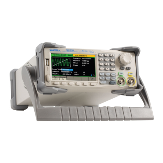
This chapter will provide a brief introduction and description for the operation and functions of the front/rear panel. The Front Panel GX 1030 has a clear and simple front panel which includes a 4.3 inch screen, menu softkeys, numeric keyboard, knob, function keys, arrow keys and channel control area. - Page 10 User Interface GX 1030 can only display parameters and waveform information for one channel at a time. The picture below shows the interface when CH1 chooses AM modulation of a sine waveform. The information displayed may vary depending on the function selected Figure 4: User Interface 1.
-
Page 11: Functional Description
Figure 5 Waveform Selections 1. Press [Waveforms] key and then press [Sine] softkey. The GX 1030 can generate sine waveforms with frequencies from 1 μHz to 30 MHz. By setting Frequency/Period, Amplitude/High level, Offset/Low level and Phase, a sine waveform with different... - Page 12 Figure 7: Square Display Interface 3. Press [Waveforms] key and then press [Ramp] softkey. The generator can generate ramp waveforms with frequencies from 1 μHz to 500 kHz and variable symmetry. By setting Frequency/Period, Amplitude/High level, Offset/Low level, Phase and Symmetry, a ramp waveform with different parameters can be generated.
- Page 13 5. Press [Waveforms] key and then press [Noise Stdev] softkey. The generator can generate noise with a 60 MHz bandwidth. By setting Stdev and Mean, noise with different parameters can be generated. Figure 10: Noise Display Interface 6. Press [Waveforms] key and then press [Page 1/2], last press the DC softkey. The generator can generate a DC signal with a level up to ±...
-
Page 14: To Set Modulation/Sweep/Burst
The modulated waveform can be changed by modifying the parameters such as Type, Source, AM Depth, AM Freq, Shape, etc. The GX 1030 can modulate waveforms using AM, FM, PM, ASK, FSK, PSK, PWM and DSB-AM, etc. Pulse waveforms can only be modulated using PWM. -
Page 15: To Turn On/Off Output
Figure 16: Burst Waveform Display Interface 4.3. TO TURN ON/OFF OUTPUT As shown in Figure 17, there are two keys on the right side of the operation panel which are used to enable / disable the output of the two channels. Choose a channel and press the corresponding Output key, the key backlight will be lighted and the output will be enabled. -
Page 16: To Use Common Function Keys
4.5. TO USE COMMON FUNCTION KEYS As shown in Figure 19, there are five keys on the operation panel which are labeled [Parameter], [Utility], [Store/Recall], [Waveforms], and [Ch1/Ch2]. The instructions below will help to familiarize you with these functions. Figure 19: Waveforms Utility and Parameter Key 1. -
Page 17: Functional Description How To Measure The Different Waveforms
5. FUNCTIONAL DESCRIPTION HOW TO MEASURE THE DIFFERENT WAVEFORMS ? 5.1. TO SET SINE WAVEFORM Press [Waveforms] key to select the waveform function and then press the [Sine softkey]. The sine waveform parameters are set by using the sine operation menu. The parameters available for sine waveforms include frequency/period, amplitude/high level, offset/low level and phase. - Page 18 Figure 21: Setting the Frequency Note: When using the numeric keyboard to enter the value, the left arrow key can be used to move the cursor backward and delete the value of the previous digit. To Set the Amplitude The amplitude setting range is limited by the Load and Frequency/Period settings. For detailed information, please refer to specifications.
- Page 19 Figure 23: Setting the Offset To Set the Phase 1. Press [Waveforms] → [Sine] → [Phase], to set the phase. The Phase shown on the screen when the instrument is powered on is the default value or the set value of last power down. 2.
-
Page 20: To Set Square Waveform
5.2. TO SET SQUARE WAVEFORM Press [Waveforms] key to select the waveform function, and press the [Square] softkey. The square waveform parameters are set by using the Square operation menu. The parameters of square waveforms include frequency/period, amplitude/high level, offset/low level, phase and duty. As shown in Figure 25, select DutyCycle. -
Page 21: To Set Ramp Waveform
Figure 26: Setting the Duty Cycle Note: The methods of setting other parameters of square signal are similar to sine waveform function. 5.3. TO SET RAMP WAVEFORM Press [Waveforms] key to select the waveform function, and press the Ramp softkey. The ramp waveform parameters are set by using the ramp operation menu. -
Page 22: To Set Pulse Waveform
To Set the Symmetry: The percentage that the rising period takes up the whole Period. Input range: 0 ~ 100 % Default Value: 50 % 1. Press [Waveforms] → [Ramp] → [Symmetry], to set the symmetry. The symmetry shown on the screen when the instrument is powered on is the default value or the set value of the last power down. 2. - Page 23 Function menu Explanations Frequency / Period Set the signal frequency or period. The current parameter will be switched with a second press. Amplitude / HighLevel Set the signal amplitude or high level. The current parameter will be switched with a second press. Offset/LowLevel Set the signal offset or low level.
-
Page 24: To Set Noise Waveform
To Set the Rise/Fall Edge Rise edge time is defined as the duration of the pulse amplitude rising from 10 % to 90 % threshold, while fall edge time is defined as duration of the pulse amplitude moving down from 90 % to 10 % threshold. The setting of rise/fall edge time is limited by the currently specified pulse width limit. - Page 25 Function menu Explanations Stdev Setting the stdev for noise waveform. Mean Setting the mean for noise waveform Menu Explanations of Noise To Set the Stdev 1. Press [Waveforms] → [Noise] → [Stdev], to set the standard deviation. The stdev shown on the screen when the instrument is powered on is the default value or the set value of last power down. 2.
-
Page 26: To Set Dc Waveform
5.6. TO SET DC WAVEFORM 1. Press [Waveform] → [Page 1/2] → [DC], to enter the following interface. Please note that there is a "DC offset" parameter in the middle of the screen. Figure 35: DC Setting Interface 5.7. TO SET ARBITRARY WAVEFORM The Arb signal consists of two types: the system‘s built-in waveforms and the user-defined waveforms. - Page 27 To select the built-in Arbitrary Waveform There are plenty of built-in Arbitrary Waveforms and user-defined Arbitrary Waveforms inside the generator. To select one of them, follow the instructions below. 1. To select the Built-in Waveform Choose [Waveforms] → [Page 2/2] → [Arb] → [Arb Type] → [Buit-in] to enter the following interface, as shown in Figure 37. Figure 37: Built-in Arbitrary Waveforms Press Common, Math, Engine, Window, Trigo or other menus to switch to the desired category (the selected category in the menu bar is highlighted), then rotate the knob to choose the desired waveform (the selected waveform is highlighted).
- Page 28 Table Built-in Waveforms Item Waveform Explanations StairUp Stair-up waveform StairDn Stair-down waveform StairUD Stair-up and down waveform Trapezia Trapezia waveform Ppulse Positive pulse Common Npulse Negative pulse UpRamp UpRamp waveform DnRamp DnRamp waveform SineTra Sine-Tra waveform SineVer Sine-Ver waveform ExpFall ExpFall function ExpRise ExpRise function...
- Page 29 Cardiac Cardiac signal Quake Analog quake waveform Chirp Chirp signal TwoTone TwoTone signal SNR signal AmpALT Gain oscillation curve AttALT Attenuation oscillation curve RoundHalf RoundHalf Waveform RoundsPM RoundsPM Waveform BlaseiWave Time-velocity curve of explosive oscillation DampedOsc Time-displacement curve of damped oscillation SwingOsc Kinetic energy –...
- Page 30 Tangent Cotangent Secant Cosecant Asin Arc sine Acos Arc cosine Atan Arc tangent ACot Arc cotangent CosH Hyperbolic cosine CosInt Integral cosine Coth Hyperbolic cotangent Trigo Csch Hyperbolic cosecant SecH Hyperbolic secant SinH Hyperbolic sine SinInt Integral sine TanH Hyperbolic tangent ACosH Arc hyperbolic cosine ASecH...
- Page 31 SquareDuty01 Square waveform with 1% duty SquareDuty02 Square waveform with 2% duty SquareDuty04 Square waveform with 4% duty SquareDuty06 Square waveform with 6% duty SquareDuty08 Square waveform with 8% duty SquareDuty10 Square waveform with 10% duty SquareDuty12 Square waveform with 12% duty SquareDuty14 Square waveform with 14% duty SquareDuty16...
- Page 32 SquareDuty70 Square waveform with 70% duty SquareDuty72 Square waveform with 72% duty SquareDuty74 Square waveform with 74% duty SquareDuty76 Square waveform with 76% duty SquareDuty78 Square waveform with 78% duty SquareDuty80 Square waveform with 80% duty SquareDuty82 Square waveform with 82% duty SquareDuty84 Square waveform with 84% duty Square...
-
Page 33: To Set Harmonic Function
5.8. TO SET HARMONIC FUNCTION The GX 1030 can be used as a harmonic generator to output harmonics with specified order, amplitude and phase. According to the Fourier transform, a periodic time domain waveform is the superposition of a series of sine waveforms as shown in the... -
Page 34: To Set Modulation Function
Menu Explanations of Harmonic To Select the Harmonic Type The GX 1030 can output odd harmonics, ever harmonics and user-defined orders of harmonics. After entering the harmonic setting menu, press Type to select the desired harmonic type. 1. Press [Even], the instrument will output fundamental waveform and even harmonics. - Page 35 (internal source only). To Select Modulation Source The GX 1030 can accept modulating signal from an internal or external modulation source. Press [Mod] → [AM] → [Source] to select Internal or External modulation source. The default is Internal. 1. Internal Source When internal AM modulation source is selected, press Shape to select Sine, Square, Triangle, UpRamp, DnRamp, Noise or Arb as modulating waveform.
- Page 36 Key Points: The GX 1030 can use one channel as a modulating source for the other channel. The following example takes the output signal of CH2 as the modulating waveform. 1. Connect the CH2 output terminal to [Aux In/Out] connector on the rear panel using a dual BNC cable 2.
- Page 37 5.9.3. FM The modulated waveform consists of two parts: the carrier and the modulating waveform. In FM, the frequency of the carrier varies with the instantaneous voltage of the modulating waveform. Press [Mod] → [Type] → [FM], the parameters of FM modulation are shown in Figure 42. Figure 42: Setting Interface of FM Modulation Function Menu Settings...
- Page 38 5.9.4. PM The modulated waveform consists of two parts: the carrier and the modulating waveform. In PM, the phase of the carrier varies with the instantaneous voltage level of the modulating waveform. Press [Mod] → [Type] → [PM], the parameters of PM modulation are shown in Figure 43. Figure 43: Setting Interface of PM Modulation Function Menu Settings...
- Page 39 5.9.5. FSK The FSK is "Frequency Shift Keying", the output frequency of which switches between two preset frequencies (carrier frequency and the hop frequency or sometimes known as mark frequency (1) and space frequency (0)). Press [Mod] → [Type] → [FSK], the parameters of FSK modulation are shown in Figure 44. Figure 44: Setting Interface of FSK Modulation Function Menu Settings...
- Page 40 Figure 45: Setting Interface of ASK Modulation Function Menu Settings Explanations Type Amplitude shift keying modulation Internal The source is internal Source External The source is external. Use the [Aux In/Out] connector at the rear panel. Set the frequency at which the output amplitude shifts between the carrier amplitude and zero Key Freq (internal modulation only): 1 mHz ~ 50 kHz.
- Page 41 Function Menu Settings Explanations Type Phase shift keying modulation Internal The source is internal Source External The source is external. Use the [Aux In/Out] connector at the rear panel. Set the frequency at which the output phase shifts between the carrier phase and 180° Key Freq/PSK Rate (internal modulation only): 1 mHz ~ 20 kHz.
-
Page 42: To Set Sweep Function
To Set Pulse Width/Duty Deviation Width Deviation represents the variation of the modulated waveform pulse width relative to the original pulse width. Press [Width Dev] to highlight the parameter, and use the numeric keyboard or arrow keys and knob to input the desired value, as shown in the Figure 48. - Page 43 „ Choose [Direction] → [Down], the generator will sweep from Stop frequency to Start frequency. Center Frequency and Frequency Span Center Frequency = (|Start Frequency + Stop Frequency|)/2Frequency Span = Stop Frequency - Start Frequency Sweep type GX 1030 provides Linear and Log sweep profiles and the default is Linear.
- Page 44 Linear sweep In linear sweep, the output frequency of the instrument varies linearly in the way of a number of Hertz per second. Choose [Sweep] → [Page 1/2] → [Type] → [Linear], there is a straight line displayed on the waveform on the screen, indicating that the output frequency varies linearly.
-
Page 45: To Set Burst Function
(N-Cycle mode), or when an external gated signals (Gated mode) is applied. Any waveform (except DC) may be used as the carrier, but noise can only be used in Gated mode. Burst Type GX 1030 provides three burst types including N-Cycle, Infinite and Gated. The default is N-Cycle. Burst Type Trigger Source... - Page 46 Figure 54: N-Cycle Burst Interface (Page 2/2) Function Menu Settings Explanations Trig Delay Set the delay time before the burst starts. Disable trigger out. Trig Out Enable trigger out. Page 2/2 Return to the previous page. Table Menu Explanations of the N-Cycle Burst (Page 2/2) Infinite In infinite mode, the cycle number of the waveform is set as an infinite value.
- Page 47 Figure 56: Gated Burst Interface Function Menu Settings Explanations Gated Use the gated mode. Positive Polarity Set the polarity for the gated signal. Negative Start Phase Set the start phase of the burst. Burst Period Set the burst period. (source internal only) Internal Choose internal source as a trigger.
-
Page 48: To Store And Recall
6. TO STORE AND RECALL GX 1030 can store the current instrument state and user-defined arbitrary waveform data in internal or external memory and recall them when needed. Press [Store/Recall] to enter the following interface. Figure 57: Store/Recall Interface (Page 1/2) -
Page 49: Storage System
Data File The GX 1030 can recall the data files in *.csv or *.dat format from external memory and transfer them into *.bin format then store them in the internal memory. When it is done, the generator will enter the arbitrary waveform interface automatically. -
Page 50: File Operation
6.3. FILE OPERATION To Save the Instrument State Users can store the current instrument state in internal and external memories. The storage will save the selected function (including the basic waveform parameters, modulation parameters and other utility settings used.) To save the instrument state, the procedures are given as follows: 1. - Page 51 To Copy and Paste File GX 1030 supports the internal and external storage to copy files from each other. For example, copy an arbitrary wave file in the U-disk to the instrument, the procedure is as follows: 1.
-
Page 52: To Set Utility Function
7. TO SET UTILITY FUNCTION With the Utility function, the user can set the parameters of the generator such as Sync, Interface, System Setting, Self Test and Frequency Counter, etc. Press [Utility] to enter the utility menu, as shown in Figure 61 and Figure 62. Figure 61: Utility Setup Interface (Page 1/2) Function Menu Settings... -
Page 53: System Settings
7.1. SYSTEM SETTINGS Press [Utility] → [System], to enter the following interface. Figure 63: System Setup Interface (Page 1/2) Function Menu Settings Explanations Number format Set the number format. English Language Set the language. Chinese Default All the settings return to default when power on. PowerOn Last All the settings return to the setting of the last power on. - Page 54 Function Menu Settings Explanations 1 min 5 min 15 min 30 min Enable or disable the screen saver. ScrnSvr 1 hour 2 hour 5 hour Disable the screen saver. System Info View the system information Firmware Update Update the firmware by the U-disk. Help View the Help information.
- Page 55 3. Power On Setting Choose the GX 1030‘s setting when the generator is powered on. 3 choices are available: the default setting and the last settings set when the unit was last powered down. Once selected, the setting will be applied when the instrument is powered on. This setting is stored in non-volatile memory and will not be influenced by the Set To Default operation.
- Page 56 4. Set to Default Press [Utility] → [System] → [Set To Default], to set the system to the default setting. The default settings of the system are as followed: Output Default Function Sine Wave Frequency 1 kHz Amplitude/Offset 4 Vpp/0 Vdc Phase 0°...
- Page 57 9. Built-in Help System The GX 1030 provides a built-in help system, by which users can view the help information at any time when operating the instrument. Press [Utility] → [System] → [Page 1/2] → [Help] to enter the following interface.
-
Page 58: Test/Cal
Figure 69: Built-in Help System Function Menu Settings Explanations Cursor upward to select. Down Cursor downward to select. Select Read the currently selected help information. Cancel Exit the built-in help system. There are 9 topics in the help list. You can use the knob and/or operation menus to select the help information that you want to read. - Page 59 Self Test Press [Utility] → [Test/Cal] → [SelfTest], to enter the following menu. Figure 71: Self Test Interface Function Menu Settings Explanations ScrTest Run screen test program. KeyTest Run keyboard test program. LEDTest Run key indicator lights test program. BoardTest Run hardware circuit self-test program.
- Page 60 2. Key Test Select KeyTest to enter the keyboard test interface, the on-screen white rectangle shapes represent the front panel keys. The circle between two arrows represents the knob. Test all keys and knob and also verify that all the backlight keys illuminate correctly. Figure 73: Key Test Interface The corresponding area of tested keys or knob would display in blue color.
-
Page 61: Frequency Counter
7.3. FREQUENCY COUNTER The GX 1030 provides a frequency counter which can measure frequencies between 100 MHz to 200 MHz. The dual channels can still output normally when the counter is enabled. Press following [Utility] → [Counter], to enter the interface. -
Page 62: Output
Save the current settings and return to the previous menu. Table Menu Explanations of Setup 1. To Select the Parameters to be measured The frequency counter on the GX 1030 can measure parameters including frequency, period, duty, positive pulse width and negative pulse width. 2. Reference Frequency System will calculate the deviation between the measured frequency and the reference frequency automatically. - Page 63 Waveforms Combining The CH1 output port of the GX 1030 outputs the waveform of CH1 in the general mode, while the waveform of CH1+CH2 can be output in the combined mode. Similarly, the CH2 output port of GX 1030 outputs the waveform of CH2 in the general mode while the waveform of CH1+CH2 can be output in the combined mode.
-
Page 64: Copy/Coupling
1. Channel Copy The GX 1030 supports state and waveform copy function between its two channels. That is to say, it copies all parameters and states (including the channel output state) and arbitrary waveform data of one channel to the other one. - Page 65 Figure 81: Channel Coupling Interface Frequency Coupling 1. To Enable Frequency Coupling Function Press [FreqCoup] to turn frequency coupling On or Off. The default is Off. 2. To Select Frequency coupling Mode Press FreqMode to choose Deviation or Ratio and then use the numeric keyboard or knob and arrow keys to input the desired value.
- Page 66 Channel Track When the track function is enabled, by changing the parameters or states of CH1, the corresponding parameters or states of CH2 will be adjusted to the same values or states automatically. At this point, the dual channels can output the same signal. Choose [Utility] →...
-
Page 67: Remote Interface
7.6. REMOTE INTERFACE The GX 1030 can be controlled remotely via USB or, LAN interfaces. Users can set the corresponding interface according to their needs. Press [Utility] → [Page 2/2] → [Interface] to open the following menu. The user can set LAN parameters or GPIB address. - Page 68 EASYWAVE X software 1. Running the EASYWAVE X software: double click the Easy wave shortcut, it will should below picture: 2. Waiting for loading file and then proceed to the next step. 3. Launch EasywaveX 4. Connection USB or LAN cable and select model. 5.
- Page 69 1. Running the SX-GENE version 2.1 software and using USB or Ethernet connection, follow "operating instructions" in pdf file. SX-GENE allows „ Transfers of arbitrary signals GX 1030, „ The recovery of a signal from a METRIX oscilloscope curve (TRC file), „ Built new waveforms, „ Configuration of the generator.
- Page 70 Remote Control via LAN The GX 1030 can communicate with a PC through LAN interface. Users can view and modify the LAN parameters. 1. Connect the device. Connect the generator to your PC or the LAN of your PC using a network cable.
-
Page 71: Sync Output
7.7. SYNC OUTPUT The generator provides Sync output through the [Aux In/Out] connector on the rear panel. When the synchronization is on, the port can output a CMOS signal with the same frequency as basic waveforms (except Noise and DC), arbitrary waveforms, and modulated waveforms (except external modulation). -
Page 72: Clock Source
7.8. CLOCK SOURCE The GX 1030 provides an internal 10 MHz clock source. It also can accept external clock source form the [10 MHz In/Out] connector at the rear panel. It can also output the clock source from the [10 MHz In/Out] connector for other devices. -
Page 73: Overvoltage Protection
Independent Mode When changing the frequency, neither channels‘ DDS resets and the phase deviation between CH1 and CH2 changes at random. When the independent mode is enabled, the phase parameter cannot be modified and the menu Phase is hidden, as shown in Figure 89. -
Page 74: Trouble Shooting
8. TROUBLE SHOOTING 1. After the generator is powered on, if the screen remains dark please do the following steps: „ Check the power cable's connection. „ Ensure the power switch is turned on. „ After the inspections above, restart the generator. „... -
Page 75: Waveforms Specifications
9.2. WAVEFORMS SPECIFICATIONS 9.2.1. SINE WAVE SPECTRUM PURITY Harmonic Distortion DC - 10 MHz -60 dBc 10 MHz - 30 MHz -50 dBc Total harmonic waveform distortion DC ~ 20 kHz 0.075 % DC ~ 10 MHz < -65 dBc Spurious signal non-harmonic 10 MHz ~ 30 MHz <... -
Page 76: Dc Offset
9.4. DC OFFSET 5 V (50 Ohm) Range DC 10 V (high impedance) Offset accuracy ≤ ± (5 % + 3 mV) setting offset value 9.5. WAVEFORM OUTPUT Impedance 50 Ohm (typical value) or High Impedance Protection short-circuit protection see "Overvoltage Protection" menu 9.6. -
Page 77: Sweep Ch1 / Ch2
9.7. SWEEP CH1 / CH2 Carrier Sine, Square, Ramp, Triangle, Noise, Arbitrary Type linear / logarithmic Direction Up / down Sweep time 1 ms ~ 500 s ± 0.1 % Trigger source Manual, external, internal 9.8. BURST CH1/CH2 Waveform Sine, Square, Ramp, Pulse, Noise, Arbitrary Type Count 1 ~ 1 000,000 cycles infinite Gated Start / Stop phase... -
Page 78: Reference Conditions
9.10.3. SYNC OUTPUT V CH 3.8 V I CH = -8 mA V OL 0.44 V I OL = 8 mA Output impedance 100 Ω Pulse width 500 ns Frequency 10 MHz Jitter (pk-pk) 6.7 ns 9.10.4. MODULATION INPUT Frequency 50 kHz Amplitude@100%modulation depth 11 to 13 Vpp... -
Page 79: Conformity To International Standards / Electrical Safety
Our site: http://www.chauvin-arnoux.com Click on "Support", then "Access the download area", then enter the name of the instrument ("GX 1030"). Connect the device to your PC using the USB cord provided. The update of the embedded software depends on its compatibility with the hardware version of the instrument. -
Page 80: Warranty
12. WARRANTY Except as otherwise stated, our warranty is valid for 24 months starting from the date on which the equipment was sold. The extract from our General Conditions of Sale is available on our website. www.chauvin-arnoux.com/en/general-terms-of-sale The warranty does not apply in the following cases: „... - Page 81 FRANCE INTERNATIONAL Chauvin Arnoux Chauvin Arnoux 12-16 rue Sarah Bernhardt Tél : +33 1 44 85 44 38 92600 Asnières-sur-Seine Fax : +33 1 46 27 95 69 Tél : +33 1 44 85 44 85 Fax : +33 1 46 27 73 89 Our international contacts info@chauvin-arnoux.com www.chauvin-arnoux.com/contacts...
Need help?
Do you have a question about the GX 1030 and is the answer not in the manual?
Questions and answers