Table of Contents
Advertisement
Quick Links
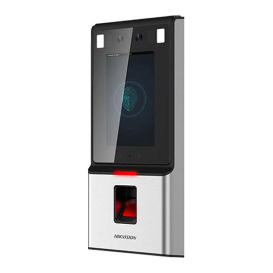
Face Recognition Terminal
Quick Start Guide
UD09017B-B
©2018 Hangzhou Hikvision Digital Technology Co., Ltd.
It includes instructions on how to use the Product. The software embodied
in the Product is governed by the user license agreement covering that
Product.
About this Manual
This Manual is subject to domestic and international copyright protection.
Hangzhou Hikvision Digital Technology Co., Ltd. ("Hikvision") reserves all
rights to this manual. This manual cannot be reproduced, changed,
translated, or distributed, partially or wholly, by any means, without the
prior written permission of Hikvision.
Trademarks
and other Hikvision marks are the property of Hikvision and
are registered trademarks or the subject of applications for the same by
Hikvision and/or its affiliates. Other trad owners. No right of license is
given to use such trademarks without express permission.
Legal Disclaimer
TO THE MAXIMUM EXTENT PERMITTED BY APPLICABLE LAW, THE
PRODUCT DESCRIBED, WITH ITS HARDWARE, SOFTWARE AND FIRMWARE,
IS PROVIDED "AS IS," WITH ALL FAULTS AND ERRORS, AND HIKVISION
MAKES NO WARRANTIES, EXPRESS OR IMPLIED, INCLUDING WITHOUT
LIMITATION, MERCHANTABILITY, SATISFACTORY QUALITY, FITNESS FOR A
PARTICULAR PURPOSE, AND NON-INFRINGEMENT OF THIRD PARTY. IN NO
EVENT WILL HIKVISION, ITS DIRECTORS, OFFICERS, EMPLOYEES, OR
AGENTS BE LIABLE TO YOU FOR ANY SPECIAL, CONSEQUENTIAL,
INCIDENTAL, OR INDIRECT DAMAGES, INCLUDING, AMONG OTHERS,
DAMAGES FOR LOSS OF BUSINESS PROFITS, BUSINESS INTERRUPTION, OR
LOSS OF DATA OR DOCUMENTATION, IN CONNECTION WITH THE USE OF
THIS PRODUCT, EVEN IF HIKVISION HAS BEEN ADVISED OF THE POSSIBILITY
OF SUCH DAMAGES.
REGARDING TO THE PRODUCT WITH INTERNET ACCESS, THE USE OF
PRODUCT SHALL BE WHOLLY AT YOUR OWN RISKS. HIKVISION SHALL NOT
TAKE ANY RESPONSIBILITIES FOR ABNORMAL OPERATION, PRIVACY
LEAKAGE OR OTHER DAMAGES RESULTING FROM CYBER ATTACK, HACKER
ATTACK, VIRUS INSPECTION, OR OTHER INTERNET SECURITY RISKS;
HOWEVER, HIKVISION WILL PROVIDE TIMELY TECHNICAL SUPPORT IF
REQUIRED.
SURVEILLANCE LAWS VARY BY JURISDICTION. PLEASE CHECK ALL RELEVANT
LAWS IN YOUR JURISDICTION BEFORE USING THIS PRODUCT IN ORDER TO
ENSURE THAT YOUR USE CONFORMS THE APPLICABLE LAW. HIKVISION
SHALL NOT BE LIABLE IN THE EVENT THAT THIS PRODUCT IS USED WITH
ILLEGITIMATE PURPOSES.
IN THE EVENT OF ANY CONFLICTS BETWEEN THIS MANUAL AND THE
APPLICABLE LAW, THE LATTER PREVAILS.
1
Installation
Installation Environment:
If Installing the device indoors, the device should be at least 2
meters away from the light, and at least 3 meters away from
the window or door.
Make sure the environment illumination is more than 100 lux.
10 Lux
100~850 Lux
>1200 Lux
2m
3m
Backlight
Direct Sunlight
Indirect Sunlight
Direct Sunlight
through Window
through Window
2
2.1
Device Wiring (Without Secure Door Control Unit)
Notes:
1. When connecting door magnetic sensor and exit button, the device and the
RS-485 card reader should use the common ground connection.
2. The Wiegand terminal displayed here is a Wiegand input terminal. You should set
the face recognition terminals Wiegand direction to"Input."If you should connect to
an access controller, you should set the Wiegand direction to"Output."For details, see
Setting Wiegand Parameters in Section 7.3.1 Communication Settings.
Before you start:
1. According to the baseline on the mounting template, stick the mounting
template on the wall or other surface, 1.4 meters higher than the ground.
2. Connect the supplied cable to the device terminals on the device rear panel.
Steps:
Drill holes on the wall or other surface according to the mounting template and
1
install the gang box (80mm×80mm).
Use two supplied screws to secure the mounting plate on the gang box.
2
Use another four supplied screws to secure the mounting plate on the wall.
Route the cables through the cable hole of the mounting plate, and connect to the
corresponding external devices'cables.
Remove the screw at the bottom of the device, and align the terminal with the
3
mounting plate and buckle them together.
Use a hex wrench to fasten the screw at the bottom.
Notes:
1. The installation height here is the recommended height. You can change it according to your
actual needs.
2. You can also install the device on the wall or other places without the gang box. For details, refer
to the User Manual.
3. For easy installation, drill holes on mounting surface according to the supplied mounting template.
孔1
孔1
将该贴纸贴在要安装的位置,根据图标来做打孔、布
线等操作;
产品最大尺寸为该贴纸最大轮廓边向外偏移10mm;
孔1:墙面固定孔;孔2:暗盒固定孔;孔3:出线孔。
孔2
2
3
推荐距地面1.40米,可根据身高进行调整。
孔2
孔2
孔3
孔2
孔3
孔1
孔1
Mounting Template
Device
Mounting Plate
Gang Box
Dimensions:
Loudspeaker
Display Screen
Indicator
Fingerprint Module
and
Card Swiping Area
Micro SIM
Card Slot
1
Power Interface
Note:
The figures are for reference only.
Wall
USB Interface
35mm
45mm
113mm
Network Interface
Wiring Terminals
Advertisement
Table of Contents

Related Manuals for HIKVISION DS-K1T606MF


Summary of Contents for HIKVISION DS-K1T606MF
- Page 1 Hikvision marks are the property of Hikvision and are registered trademarks or the subject of applications for the same by Hikvision and/or its affiliates. Other trad owners. No right of license is given to use such trademarks without express permission.
- Page 2 Regulatory Information Device Wiring (With Secure Door Control Unit) Activation FCC Information Power on and wire the network cable after installation. Please take attention that changes or modification not expressly approved by the party responsible for compliance could void the user’s authority to operate the equipment. You should activate the device before the first login.
Need help?
Do you have a question about the DS-K1T606MF and is the answer not in the manual?
Questions and answers