Table of Contents
Advertisement
Quick Links
S
p
e
c
S
p
e
c
S
p
e
c
CHAUVIN-ARNOUX Test and Measurement Division
Tel. +33 (0)4.50.64.22.22 - Fax +33 (0)4.50.64.22.00
Copyright ©
1
G
H
z
1
G
H
z
1
G
H
z
t
r
u
m
A
n
t
r
u
m
A
n
t
r
u
m
A
n
'
'
'
U
s
e
r
s
m
a
n
u
a
U
s
e
r
s
m
a
n
u
a
U
s
e
r
s
m
a
n
u
6, avenue du Pré de Challes
F - 74940 ANNECY-LE-VIEUX
a
l
y
z
e
r
a
l
y
z
e
r
a
l
y
z
e
r
l
l
a
l
Parc des Glaisins
X02827C00 - Ed. 1 - 04/16
Advertisement
Table of Contents

Related Manuals for Metrix MTX I 050-PC


Summary of Contents for Metrix MTX I 050-PC
- Page 1 ’ ’ ’ CHAUVIN-ARNOUX Test and Measurement Division Parc des Glaisins 6, avenue du Pré de Challes F - 74940 ANNECY-LE-VIEUX Tel. +33 (0)4.50.64.22.22 - Fax +33 (0)4.50.64.22.00 Copyright © X02827C00 - Ed. 1 - 04/16...
-
Page 2: Table Of Contents
Contents Contents Contents ........................2 General Instructions ....................3 Description of the Instrument ................... 5 Control and display unit ......................7 Functional Description ....................8 Detailed description of the fields ................... 8 Menus ........................11 File ............................11 Setup ............................12 Options ..........................144 ? menu ..........................155 Technical Specifications .................. -
Page 3: General Instructions
General instructions General Instructions Thank you for purchasing this METRIX spectrum analyzer. Introduction This device complies with safety standard EN 61010-1: 2001 applicable to electronic measuring instruments. For optimum service, read this manual carefully and comply with the operating precautions. - Page 4 General instructions General Instructions (contd.) This equipment is warranted to be free of defects in materials or Warranty workmanship, in accordance with the general terms and conditions of sale. During the warranty period, repairs to the instrument may be carried out by the manufacturer only, who, at its sole discretion, may either repair the instrument or replace all or part of it.
-
Page 5: Description Of The Instrument
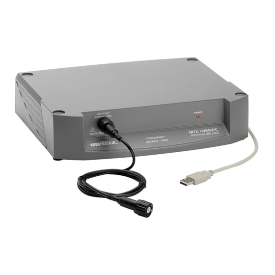
Description of the instrument Description of the instrument Front panel Illustration Input 50 On/Off 400kHz - 1GHz + 25dBm max. max. Markings Rear panel HP (demod) USB (for PC) Mains connector Illustration Markings 1 GHz Spectrum Analyzer... - Page 6 Description of the instrument Description of the instrument (contd.) Presentation This spectrum analyzer is a bench-top device used in conjunction with a PC connected by a USB cable. The user interface is not displayed directly on the instrument, but as part of the operating software.
-
Page 7: Control And Display Unit
Description of the instrument Description of the instrument (contd.) Control and display unit Item Explanation Menus Span frequencies Span type and speed Filters Reference level Delta cursor data Peak cursor Free cursor RUN / STOP button UNCAL message Graph Spectrum Memory spectrum Averaging coefficient Visual indicators of the selected spectrum... -
Page 8: Functional Description
Functional Description Functional Description Detailed description of the fields Start Center Stop These 3 values characterize the frequency sweep for the span selected: frequencies Start indicates the span's start frequency Center indicates the span's center frequency Stop indicates the span's stop frequency When one of the 3 frequencies is changed, the other 2 are automatically recalculated on the basis of the span. - Page 9 Functional Description Functional Description (contd.) Example The span is 100MHz with: Start at 200 MHz Center at 250 MHz Stop at 300 MHz If the span changes to 50 MHz, there are 3 possibilities, depending on the last frequency modified: If the last frequency Then …...
- Page 10 Functional Description Functional Description (contd.) Reference level This field indicates the maximum level that can be analyzed and represented on the graph. REF LVL The default reference level is 0dBm. Users should choose: a REF. LEVEL of +20dBm to analyze strong signals ...
-
Page 11: Menus
Menus Menus File Open Span … opens a *.spn file. The recorded spectrum is displayed in a different color on the graph and the analyzer is restored to the same configuration as that of the recorded spectrum. The 2 spectrums can then easily be compared one above the other. The name of the open file is displayed in the title bar. -
Page 12: Setup
Menus Menus (contd.) Setup Run / Stop This submenu serves the same purpose as the button on the front panel. It freezes or reinitializes the spectrums. Detector selects the type of measurement: Peak or Quasi-Peak (Q-Peak). The Peak detector is used by default. The Q-Peak detector is reserved for EMC measurements where the rate is 1 measurement/second. - Page 13 Menus Menus (contd.) Averaging activates averaging of the spectrum's values. The possible coefficients are: x 2, x 4, x 8, x 16, x 32, x 64. The average is calculated after each new acquisition. It is calculated as follows: Average = Previous average x (n-1) / n + new acquisition / n "n"...
-
Page 14: Options
Menus Menus (contd.) Options Search function of all Peaks (from 1 to 10) Peak These submenus configure the spectrum's management in the Memory memory. The options are: "Off” erases the memory "Reference" represents the memory only "Span - Reference" represents the difference between the current spectrum and the memory. - Page 15 Menus Menus (contd.) Colors This submenu configures: the style of the waveform: the color of the waveform on the graph the color of the cursors. This submenu configures the software in 1 of the 5 languages Language available: - French - English...
-
Page 16: Technical Specifications
Technical Specifications Technical Specifications Only values assigned tolerances or limits are guaranteed values. These values are established after a minimum warm-up time of 30 minutes. Values without a tolerance are provided for information purposes only. Frequency 400 kHz - 1 GHz Range of use Accuracy... - Page 17 Technical Specifications Technical Specifications (contd.) Input Max. input voltage , + 25dBm Impedance 50 Attenuator 20dB Connector Cursors Quantity Resolution 0.3dB / 10kHz and 0.1dB / 10kHz with averaging Mode Relative (delta function) Accuracy Identical to the accuracy of the signal amplitude Functions Demodulation Tone: Reduced BW (approx.
- Page 18 General Specifications General Specifications General Power supply 230V , ± 10%, approx. 50Hz 7W 270 (L) x 63 (H) x 215 (W) Dimensions (mm) Weight < 1.7kg Environment Reference temperature 18°C to 28°C Storage temperature -20°C to 70°C ...
Need help?
Do you have a question about the MTX I 050-PC and is the answer not in the manual?
Questions and answers