
Related Manuals for Pego VISION Series


Summary of Contents for Pego VISION Series
- Page 1 VISION 2PLT Use and maintenance manual ENGLISH READ AND KEEP ELECTRICAL BOARDS FOR REFRIGERATING INSTALLATIONS REV. 02-18...
- Page 2 VISION 2PLT USE AND MAINTENANCE MANUAL Pag. 2 Rev. 02-18...
-
Page 3: Table Of Contents
VISION 2PLT CONTENTS INTRODUCTION CHAP. 1 Pag. 4 General Pag. 5 Product ID codes Pag. 5 Overall dimensions Pag. 5 Identification data INSTALLATION CHAP. 2 Pag. 6 Important information for installer Pag. 6 Standard assembly and use kit Pag. 7 Installation FUNCTIONS CHAP. -
Page 4: General
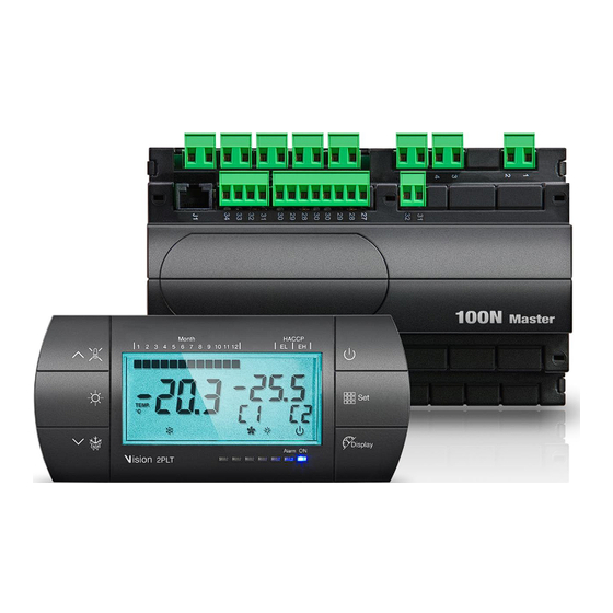
VISION 2PLT CHAPTER 1: INTRODUCTION GENERAL The electronic controllers of the VISION series have been designed to control static or ventilated cold rooms. The VISION 2 PLT electronic panel allows the user to control all the components on a refrigeration unit equipped with a double system. The panel allows the user to control the essential components of a refrigeration system with up to two compressors, a double evaporator (fans and defrosting elements) and a cold room light. -
Page 5: Identification Data
CHAP. 1 - Introduction VISION 2PLT PRODUCT ID CODES VISION 2PLT Controller for cold storage cell with double system. OVERALL DIMENSIONS Dimensions in mm VISION 2PLT 100N MASTER3 2PLT DENTIFICATION DATA The unit described in this manual has, on its side, an ID plate showing all the relevant identification data: •... -
Page 6: Important Information For Installer
CHAP. 2 - Installation VISION 2PLT CHAPTER 2: INSTALLATION IMPORTANT INFORMATION FOR THE INSTALLER 1. Install the device in places where the protection rating is observed and try not to damage the box when drilling holes for wire/pipe seats. 2. Do not use multi-polar cables in which there are wires connected to inductive/power loads or signalling wires (e.g. - Page 7 CHAP. 2 - Installation VISION 2PLT INSTALLATION Fig. 1: Position the 100N MASTER3 module on the DIN guide and close the 2 lower hooks to lock it on the same. Fig. 2: Fix the VISION 2PLT console using the two screws to be inserted in the slots underneath the keys frame.
- Page 8 CHAP. 3 - Functions VISION 2PLT CHAPTER 3: FUNCTIONS FUNCTIONS CONTROLLED BY THE VISION 2PLT Display and adjustment of room temperature. Display of evaporator 1 and evaporator 2 temperature. Display of ambient 1 and ambient 2 temperature. System control activation/deactivation. Operation with single set-point and control of two motor condensing units with delays between the two parameter-set starts.
-
Page 9: Technical Characteristics
CHAP. 4 - Technical characteristics VISION 2PLT CHAPTER 4: TECHNICAL CHARACTERISTICS TECHNICAL CHARACTERISTICS Power supply 230 V~ 10% 50/60Hz Voltage Max. power absorption (only electronic control) ~ 8 VA Climatic conditions Working temperature -5 ÷ +50 °C Storage temperature -10 ÷... - Page 10 The intervention service in warranty can be refused when the equipment is modified or transformed. Under no circumstances Pego S.r.l. will be liable for any loss of data and information, costs of goods or substitute services, damage to property, people or animals, loss of sales...
-
Page 11: Panel Layout
CHAP. 5 - Data programming VISION 2PLT CHAPTER 5: DATA PROGRAMMING PANEL LAYOUT State led KEYPAD FUNCTIONS PROBE VALUES / TIME DISPLAY (if pressed for more than 3 seconds the current time is displayed for a few seconds) ... - Page 12 CHAP. 5 - Data programming VISION 2PLT DOWN / ENTER MANUAL DEFROST MENU (if long pressed) ROOM LIGHT DISPLAY LCD Ambient temperature / parameters Value of ambient probe / defrost 1 probe / defrost 2 probe / current day / parameter value / alarm code System status / time / time parameter values Written...
-
Page 13: General
CHAP. 5 - Data programming VISION 2PLT Programming (control is in programming mode) Cold (compressor call indicator, if flashing a compressor 1 is waiting C1 delay) Defrost (if flashing an evaporator is in drip mode) (flashing during fan stop – parameter F5) Fans Light Alarm... -
Page 14: Setting And Displaying The Set-Points
CHAP. 5 - Data programming VISION 2PLT SETTING AND DISPLAYING THE SET-POINTS 1. Press the SET key to display the current SET-POINT (temperature). 2. Hold down the SET key and press the () or () keys to modify the SET-POINT. 3. -
Page 15: List Of Level 1 Variables
CHAP. 5 - Data programming VISION 2PLT LIST OF LEVEL 1 VARIABLES (User level) VARIABLE MEANING VALUES DEFAULT Temperature differential referred to main SETPOINT 0,2 ÷ 10,0 °C 2,0°C (both set points where double) 0 ÷ 24 hours Defrost interval (hours). 4 hours In the case of the double evaporator defrost start is simultaneous. -
Page 16: Level 2 Programming
CHAP. 5 - Data programming VISION 2PLT 00:00:00 Programming defrost times, evaporator 1 d41…d46 ÷ 00:00:00 It is possible to set up to 6 defrosting times 23:59:00 00:00:00 Programming defrost times, evaporator 2 d51…d56 ÷ 00:00:00 It is possible to set up to 6 defrosting times 23:59:00 LEVEL 2 PROGRAMMING (Installer level) 5.10... -
Page 17: List Of Level 2 Variables
CHAP. 5 - Data programming VISION 2PLT LIST OF LEVEL 2 VARIABLES (Installer level) 5.11 VARIABLE MEANING VALUES DEFAULT Number of compressors (or solenoids or 1 = 1 system systems) 2 = 2 system 1 = 1 evaporator Number of evaporators 2 = 2 evaporators Single or double set-point setting 1 = one setting only... - Page 18 CHAP. 5 - Data programming VISION 2PLT MEANING VARIABLE VALUES DEFAULT Duration of compressor ON time in the case of faulty ambient probe (emergency mode). If CE1=0 the emergency mode in the presence of 0 ÷ 240 minutes error E1/E2 remains disabled, the compressor (0=disabled) remains off and defrosting is prevented in order to conserve the remaining cold.
- Page 19 CHAP. 5 - Data programming VISION 2PLT VARIABLE MEANING VALUES DEFAULT FAN shutdown TEMPERATURE The fans will stop if the temperature value read by -45 ÷ 99°C +99°C the evaporator sensor is higher than this value. Fst differential 1 ÷ 10 °C 2 °C 2 = door resistance deicing (NO) 1 = General alarm (NO)
-
Page 20: Switching On The Vision 2Plt Electronic Controller
CHAP. 5 - Data programming VISION 2PLT SWITCHING ON THE VISION 2PLT ELECTRONIC CONTROLLER 5.12 After wiring the controller correctly, power up at 230VAC; the panel will immediately emit a beep and all segments and LEDs come on simultaneously for a few seconds. COMPRESSOR ACTIVATION/DEACTIVATION CONDITIONS 5.13 The VISION 2PLT controller activates the compressor when cold room temperature... -
Page 21: Defrost Management
CHAP. 5 - Data programming VISION 2PLT DEFROST MANAGEMENT 5.17 The defrost start mode are as follows: - manual defrosting: pressing the dedicated key (see section 5.2) you will enter the defrost start / stop management menu. In particular, pressing it is possible to choose the defrost of plant 1 (written “1”), plant 2 (written “2”) or both (written “1-2”). -
Page 22: Hot Gas Defrosting
CHAP. 5 - Data programming VISION 2PLT HOT GAS DEFROSTING 5.19 Set parameter d1=1 or d1=2 to manage defrost in cycle inversion mode. During the entire defrosting process the compressor and defrost relays are activated. During dripping (d7) the compressor stops and, if d1=2, the defrost relays remain activated in order to ensure the ignition of the resistances of the basins. -
Page 23: Telenet Monitoring/Supervision System
CHAP. 6 - Options VISION 2PLT CHAPTER 6: OPTIONS TELENET MONITORING/SUPERVISION SYSTEM In order to connect the board to the TeleNET network, follow the diagram below. Configure the instrument with reference to the TeleNET manual. IMPORTANT: During configuration of the “Module”, select "PLUS 200 2 PLT / VISION 100 2PLT Instrument ". -
Page 24: Diagnostics
CHAP. 7 - Diagnostics VISION 2PLT CHAPTER 7: DIAGNOSTICS DIAGNOSTICS In case of anomalies, the VISION 2PLT controller warns the operator using alarm codes shown by the display and an acoustic signal emitted by a buzzer inside the Operational console. If the alarm EL or EH falls without operator intervention the control keeps track of the error over time. - Page 25 CHAP. 7 - Diagnostics VISION 2PLT Man in room alarm Reset the alarm switch The man in room alarm switch in the room has been inside the cold room. pressed to indicate a dangerous situation. Door open alarm. When the door switch opens and the Tdo time ...
-
Page 26: Eu Declaration Of Conformity
DEL FABBRICANTE: THIS DECLARATION OF CONFORMITY IS ISSUED UNDER THE EXCLUSIVE RESPONSIBILITY OF THE MANUFACTURER: PEGO S.r.l. Via Piacentina 6/b, 45030 Occhiobello (RO) – Italy – DENOMINAZIONE DEL PRODOTTO IN OGGETTO / DENOMINATION OF THE PRODUCT IN OBJECT MOD.: VISION 2 PLT IL PRODOTTO DI CUI SOPRA E’... -
Page 27: 100N Master3 Connection Layout
Attachments VISION 2PLT 100N MASTER3 CONNECTION LAYOUT USE AND MAINTENANCE MANUAL Rev. 02-18 Pag. 27... - Page 28 Attachments VISION 2PLT Power supply: DESCRIPTION TERMINAL N – L Power supply terminal 1 – 2 1 – 2 115÷230Vac ±10% 50/60Hz Assorbimento: 20 VA max. Connect ground to terminal 45 of the console (functional earth). This connection helps to limit the effects of electromagnetic noise on the control system.
- Page 29 Attachments VISION 2PLT Analog inputs: PROBE TYPE DESCRIPTION PIN TERMINAL 29 – 30 NTC 10K Ambient 1 probe 31 – 32 NTC 10K Ambient 2 probe 33 – 34 NTC 10K Evaporator 1 probe 35 – 36 NTC 10K Evaporator 2 probe Digital inputs: DESCRIPTION FACTORY DEFAULT SETTINGS...
- Page 30 VISION 2PLT Notes: USE AND MAINTENANCE MANUAL Pag. 30 Rev. 02-18...
- Page 31 VISION 2PLT USE AND MAINTENANCE MANUAL Pag. 31 Rev. 02-18...
- Page 32 Tel. +39 0425 762906 Fax +39 0425 762905 e.mail: info@pego.it – www.pego.it AFTER-SALES ASSISTANCE CENTRE Tel. +39 0425 762906 e.mail: tecnico@pego.it Distributor: USE AND MAINTENANCE MANUAL Pag. 32 PEGO s.r.l. reserves the right to make amendments to this user manual at any moment. Rev. 02-18...
Need help?
Do you have a question about the VISION Series and is the answer not in the manual?
Questions and answers