Table of Contents
Advertisement
Quick Links
Advertisement
Table of Contents

Related Manuals for Watson Marlow Pumps 323E


Summary of Contents for Watson Marlow Pumps 323E
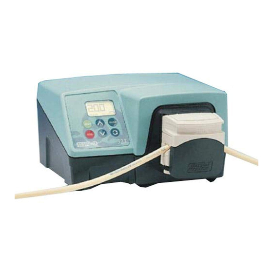
- Page 1 323E, 323S, 323U, 323Du 323esudu-gb-04.pdf...
- Page 2 Declar lara a a a a tions tions tions tions tions When this pump unit is used as a stand alone pump it complies with: Machinery Directive Declaration of 98/37/EC EN60204-1, Low Voltage Directive 73/23/EEC EN61010-1, EMC Directive conformity 89/336/EEC, EN50081-1/EN50082-1. Declaration of When this pump unit is to be installed into a machine or is to be assembled with other Incorporation...
-
Page 3: Troubleshooting
Safety Safety Safety Safety Safety In the interests of safety, this pump and the tubing selected should only be used by competent, suitably trained personnel after they have read and understood this manual, and considered any hazard involved. Any person who is involved in the installation or maintenance of this equipment should be fully competent to carry out the work. -
Page 4: Switching The Pump On
Features 323E 323S 323U 323Du Manual control • • • • 15-400 rpm 27:1 speed control • 3-400 rpm 133:1 speed control • • • 1.5-220 rpm 147:1 speed control • • • Auto-restart • • • Keypad lock •... -
Page 5: Manual Control
We recommend that the speed is reduced to a minimum before starting the pump. • The 323E increments in steps of 5rpm. The 323S, 323U and 323Du increment in steps of 1rpm. • Press the key to reverse the direction of rotation. - Page 6 MemoDose 323S 323U 323Du The pump can dispense a set quantity or dose of fluid each time the key is pressed. This is the MemoDose facility. Set the pump speed When required and direction. Place a volume of fluid has been suitable measuring dispensed, press the container at the outlet...
-
Page 7: Automatic Operation With Analogue Signals, Remote Control, Or Rs232 Link
Analogue control Return to manual mode mode speed control Return to manual RS232 control speed control Pressing the key on 323E and 323S will display “man” mode for 2 seconds then return to current set speed. Return to manual speed control... - Page 8 Analogue signals and remote control Analogue signals and remote control Analogue signals and remote control Analogue signals and remote control Analogue signals and remote control 323U 323Du Pump starting and direction may be remotely controlled by switches, and speed by analogue signals, connected to the 25-way D connector at the rear of the pump.
- Page 9 To invert the stop/start action of the switch or TTL compatible signal: • Turn off the mains power switch at the rear of the pump. • Hold down the keys. Turn on the mains power switch. • The display will show the present signal setting; RS for factory default response or IRS for inverted signal response.
-
Page 10: Rs232 Serial Link
Speed A remote potentiometer may be connected to control the pump speed. Use a potentiometer of between 1K and 10KOhms, with a minimum power of 0.25W. Connect the potentiometer as shown. Set the pump to analogue control. Do not apply another voltage or current control signal while using a remote potentiometer. RS232 serial link RS232 serial link RS232 serial link... - Page 11 RS232 settings Pump interface pin Function Baud 9600 Stop bits RX (Receive data) Data bits TX (Transmit data) Parity None Flow Control None GND (Ground) Echo RS232 command codes These are the codes to control the pump with the RS232 serial link. They must be sent to the pump from a computer serial port (or equivalent).
-
Page 12: Care And Maintenance
Care and maintenance Care and maintenance Care and maintenance Care and maintenance Care and maintenance The pump is sealed to IP31 and is suitable for wipe down cleaning. Do not use solvents, mechanical scourers, strong organic acids, or alkali based cleaning solutions. Remove any tubing, detach the pumphead, and wash the pumphead thoroughly with a mild solution of detergent in water. -
Page 13: Part Numbers
Part numbers Part numbers Part numbers Part numbers Part numbers Drives only Part number Drive type Drive speed Pumphead Mains lead type 036.3124.00U 323E 036.3132.00U 323S 036.3134.00U 323S 036.3142.00U 323U 036.3144.00U 323U 036.3152.00U 323Du 036.3154.00U 323Du Complete pump assemblies Part number... - Page 14 313D and 314D pumpheads 313D and 314D pumpheads 313D and 314D pumpheads 313D and 314D pumpheads 323E 323S 323U 323Du The 313D pumphead has three rollers and is designed to provide higher flow rates. The 314D pumphead has four rollers to provide greater pumping precision with less pulsation in the flow. Both designs are available for 1.6mm and 2.4mm wall tubes.
-
Page 15: Installation
Installation Installation Installation Installation Installation 323 drives require a mounting plate to attach a 313 or 314 pumphead. Engage the pumphead drive slot with the end of the pump drive shaft. Continue to align the pumphead until the bayonet engages with the mounting plate. Turn the pumphead clockwise until it locks into an upright position. - Page 16 • Select enough tube length for the curve of the pump track. Slide the tube into the open pumphead. The tube must not be twisted or stretched against the rollers. • Ensure the tubing locates in the centre of the tube clamps. Carefully lower the track. Check that the tube is not crushed in the clamps or over stretched.
-
Page 17: Flow Rates
Symbols Symbols Symbols Symbols Symbols #Tube number Tube bore Flow rates Flow rates Flow rates Flow rates Flow rates Flow rates were obtained using silicone tubing with the pumphead rotating clockwise, pumping water at 20°C with zero suction and delivery pressures. For critical applications determine flow rates under operating conditions. - Page 18 Maxim Maximum n Maxim um n um n um number of umber of umber of umber of pumpheads pumpheads pumpheads pumpheads..Maxim Maxim um n umber of pumpheads 313D 313D, 314D Pla 313D , 314D Pla , 314D Platin , 314D Pla tinum Silicone...
- Page 19 1.6mm w 1.6mm wall tube f 1.6mm w all tube f all tube f all tube for 313D or 313D or 313D or 313D, 314D pumpheads , 314D pumpheads , 314D pumpheads , 314D pumpheads 1.6mm w 1.6mm w all tube f or 313D , 314D pumpheads (1.6mm) Product codes.
- Page 20 314MC and 318MC microcassette pumpheads 314MC and 318MC microcassette pumpheads 314MC and 318MC microcassette pumpheads 314MC and 318MC microcassette pumpheads 314MC and 318MC microcassette pumpheads 323S 323U 323Du 314MC and 318MC pumpheads must not run at speeds greater than 110rpm. Each pumphead offers 5 pumping channels, and the manifold tubing is preloaded in removable cassettes.
- Page 21 T T T T T ube loading ube loading ube loading ube loading ube loading Tube size is identified by the colour of the three collars. These collars divide the manifold tube element into two alternative pumping segments. Either segment may be fitted in the pump cassette and this doubles the working life obtained from each manifold tube element.
-
Page 22: Pumphead Spares
• Flip the cam lever upright to lock the cassette in the pumphead. • The cam lever controls the occlusion of the tube against the rollers. To pump against higher pressure the cam lever may be moved beyond the vertical position. Tube life will be shortened and drive torque will be increased. This will reduce the number of cassettes that may be fitted to the pump. - Page 23 Flow rates Flow rates Flow rates Flow rates Flow rates Flow rates were obtained using silicone tubing with the pumphead rotating clockwise, pumping water at 20°C with zero suction and delivery pressures. For critical applications determine flow rates under operating conditions.
- Page 24 Tube code bore Marprene * Silicone Orange/black 0.13mm / 0.005” 981.0013.000 Orange/red 0.19mm / 0.007” 981.0019.000 Orange/blue 0.25mm / 0.010” 979.0025.000 981.0025.000 Orange/green 0.38mm / 0.015” 979.0038.000 981.0038.000 Orange/yellow 0.50mm / 0.020” 979.0050.000 981.0050.000 Orange/white 0.63mm / 0.025” 979.0063.000 981.0063.000 983.0063.000 Black/black 0.76mm / 0.030”...
- Page 25 501RL pumphead 501RL pumphead 501RL pumphead 501RL pumphead 501RL pumphead The 501RL and 501RL2 pumpheads are suitable for tubing with internal diameters up to 8.0mm. The 501RL is set during manufacture for use with 1.6mm wall tubing and 501RL2 is set for 2.4mm wall tubing. The spring-loaded rollers give extended tube life.
- Page 26 The tube clamps can accommodate various tube diameters by pushing in, or pulling out, the grip bars within the clamp. Set the clamps to apply the minimum necessary pressure to the tubing. Restart the pump. Free the downstream clamp for a short time, while the pump is running, so that the tube can find its natural length.
- Page 27 Pumphead spar Pumphead spares Pumphead spar Pumphead spar Pumphead spar 053.0001.L00 501RL complete pumphead 053.0001.L20 501RL2 complete pumphead MN0377M Lockable guard FN4502 Lock FN2341 Hinge screw MN0266M Hinge MNA0114A Tube clamp assembly FN2332 Screw MN0011T Main roller MNA0143A 501RL Rotor Assembly SG001 Springs for 501RL (blue) SG002...
- Page 28 Flow rates Flow rates Flow rates Flow rates Flow rates Flow rates were obtained using silicone tubing with the pumphead rotating clockwise, pumping water at 20°C with zero suction and delivery pressures. For critical applications determine flow rates under operating conditions.
- Page 29 323 Dimensions (mm) 323 Dimensions (mm) 323 Dimensions (mm) 323 Dimensions (mm) 323 Dimensions (mm) 323E/D 323S/D 323U/D 323Du/D 323E/D 323S/D 323U/D 323Du/D 323E/D 323S/D 323U/D 323Du/D 323E/D 323S/D 323U/D 323Du/D 323E/D 323S/D 323U/D 323Du/D 323S/MC 323U/MC 323Du/MC 323S/MC 323U/MC 323Du/MC...
- Page 30 Product Use and Decontamination Certificate In compliance with the UK Health & Safety at Work Act and the Control of Substances Hazardous to Health Regulations you, the user are required to declare the substances which have been in contact with the product(s) you are returning to Watson-Marlow or any of its subsidiaries or distributors.
Need help?
Do you have a question about the 323E and is the answer not in the manual?
Questions and answers