Table of Contents
Advertisement
Quick Links
Watson-Marlow 720DuN User Manual
WATSON-MARLOW BREDEL MANUALS
m-720dun-gb-02
Watson-Marlow 720DuN pumps
Contents
1
2
3
4
5
6
7
8
8.1
9
9.1
9.2
3
3
4
5
7
8
10
15
17
18
19
20
22
23
23
26
26
26
27
27
27
28
29
29
29
31
32
36
37
38
39
41
41
41
42
43
43
44
44
45
46
47
49
50
51
51
52
53
53
54
54
55
55
56
57
57
58
60
60
60
61
61
62
65
66
67
67
68
68
69
1
Advertisement
Table of Contents

Related Manuals for Watson Marlow Pumps 720DuN


Summary of Contents for Watson Marlow Pumps 720DuN
-
Page 1: Table Of Contents
18 Setup output 18.1 Trim 22.7 Run/stop input 18.2 Analogue 22.8 Direction input 18.2.1 Input 1: speed 22.9 Auto / manual toggle 18.2.2 Scaling - stroke input 18.2.3 Trim 18.2.4 Exit 18.3 Display 18.4 Pump I/D Watson-Marlow 720DuN User Manual... - Page 2 39 Publication history and 720REX 40 Decontamination certificate safe-guarding 28.4 All 720R and 720RE pumping conditions 28.5 All 720R and 720RE pumpheads: fluid management 29 Pumphead fitting 29.1 Removing and refitting the pumphead 29.2 Fitting an extension pumphead Watson-Marlow 720DuN User Manual...
-
Page 3: Declaration Of Conformity
1 Declaration of conformity This declaration was issued for Watson-Marlow 720DuN pumps on May 1, 2007. When this pump unit is used as a stand-alone pump it complies with: Machinery Directive 2006/42/EC, EMC Directive 2004/108/EC. This pump is ETL listed: ETL control number 3050250. Cert to CAN/CSA std C22.2 No 61010-1. -
Page 4: Five-Year Warranty
The drive they are attached to is subject to the five-year war- ranty as set out here. Ancillaries such as leak detectors are excluded. Watson-Marlow 720DuN User Manual... -
Page 5: When You Unpack Your Pump
Check that all components are present. Inspect components for damage in transit. If anything is missing or damaged, contact your distributor immediately. Components supplied 720DuN pumps supplied as: Dedicated 720 pump drive unit fitted with 720R, 720RE, 720RX or 720REX pumpheads (see 8. Pump specifications). -
Page 6: Information For Returning Pumps
If the pump has been used, the fluids that have been in contact with the pump and the cleaning procedure must be specified along with a statement that the equipment has been decontaminated. Watson-Marlow 720DuN User Manual... -
Page 7: Peristaltic Pumps-An Overview
Peristaltic pumps operate on the positive displacement principle. They are particu- larly suitable for metering, dosing and dispensing applications. Pumps are easy to install, simple to operate and inexpensive to maintain. Watson-Marlow 720DuN User Manual... -
Page 8: Safety Notes
Any person who is involved in the installation or periodic maintenance of this equip- ment should be suitably skilled or instructed and supervised using a safe system of work. In the UK this person should also be familiar with the Health and Safety at Work Act 1974. Watson-Marlow 720DuN User Manual... - Page 9 No attempt should be made to run the drive without a pumphead fitted. Lifting The unit weighs more than 18kg (the exact weight depends on model and pump- head—see 8 Pump specifications). Lifting should be performed according to standard health and safety guidelines. Watson-Marlow 720DuN User Manual...
-
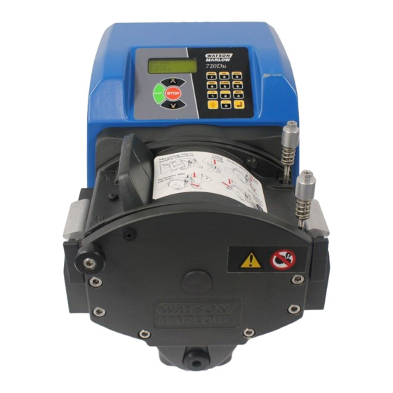
Page 10: Pump Specifications
The same information is carried on the drive’s backplate, accessible when the 720N module is removed. The picture below is how a 720Du looks from the box. The num- ber of connectors varies according to the model. Watson-Marlow 720DuN User Manual... - Page 11 720DuN, IP66 NEMA 4X model This pump can be controlled from the keypad or remotely. It features: Manual control Speed adjustment; run and stop; direction control; keypad scaling; “max” key for rapid priming. Remote control The pump can be digitally controlled with a contact closure or logic input signal.
- Page 12 * 720N cased pumps are rated to NEMA 4X (indoor use) only. Unit weights Drive only + 720R, 720RE + 720RX, 720REX IP66 NEMA 4X 18.5kg, 40lb 13oz 25kg, 55lb 2oz 31.5kg, 69lb 7oz Watson-Marlow 720DuN User Manual...
- Page 13 NEMA 4X to NEMA 250* (indoor use). Suitable for heavy industrial, process and dirty environments. The drive uses a Enclosure rating - 720DuN Gore membrane vent to equalise the pressure inside the enclosure and to prevent ingress of water and corrosive vapours.
- Page 14 Pumps and pump units for liquids—common safety requirements: BS EN 809 UL 61010A-1 CAN/CSA-C22.2 No 61010-1 Other Conducted emissions FCC 47CFR, Part 15.107 standards Radiated emissions FCC 47CFR, Part 15 NEMA 4X to NEMA 250 (indoor use) for IP66 products only Watson-Marlow 720DuN User Manual...
-
Page 15: Dimensions
8.1 Dimensions 86mm 242mm 180mm 164mm 186mm 65mm 346mm 508mm 150mm 658mm 305mm 160mm 61mm 221mm 280mm Watson-Marlow 720DuN User Manual... -
Page 16: Good Pump Installation Practice
(2ft) of the connecting pipework rises as it approaches the pumphead on both the inlet and discharge sides. This helps the sliders which hold the element in place to find their optimum position. Failure to do this may result in premature element fail- ure. Watson-Marlow 720DuN User Manual... -
Page 17: Do's And Do Not's
Do not run the pump with no tube or element fitted to the pumphead. If the direc- tion is changed, the rotor will continue turning as it tries to reverse and the software will flag an error condition. Watson-Marlow 720DuN User Manual... -
Page 18: Connecting This Product To A Power Supply
IP66 specification pumps are supplied with no plug. Wiring a mains plug must only be undertaken by suitably skilled, qualified personnel. Conductor coding European North American line brown black neutral blue white ground green/yellow green Watson-Marlow 720DuN User Manual... -
Page 19: Start-Up Check List
Ensure that proper connections are achieved between the pump tube and suction and discharge piping. Ensure proper connection has been made to a suitable power supply. Ensure that the recommendations in section 9 Good pump installation practice are followed. Watson-Marlow 720DuN User Manual... -
Page 20: Switching The Pump On For The First Time
The rotation symbol on the display indicates clockwise rotation. The default speed setting is 300 rpm, but 360 rpm is available (see 18.13 Set maximum allowed speed). Other initial start-up operational parameters are listed in the table below. Watson-Marlow 720DuN User Manual... - Page 21 Note: High is equivalent to the common and normally open contacts of the relay on the module board being closed. The pump is now ready to operate according to the defaults listed above. All operating parameters may be changed by means of key-presses. See 14 Manual operation. Watson-Marlow 720DuN User Manual...
-
Page 22: Switching The Pump On In Subsequent Power Cycles (If Not In Auto-Restart Mode)
Start-up defaults are those in place when the pump was switched off last. Check that the pump is set to operate as you require it. The pump is now ready to operate. All operating parameters may be changed by means of key-presses. See 14 Manual operation below. Watson-Marlow 720DuN User Manual... -
Page 23: Manual Operation
Run time. An example is shown here. The default can be altered from within the Setup menu (see 18.3 Display). Watson-Marlow 720DuN User Manual... - Page 24 0rpm by a further press on the DOWN key. The pump is still in the running state and the rotation symbol will continue to move. Press the UP key to return the pump to the minimum speed. Watson-Marlow 720DuN User Manual...
- Page 25 Only the START and STOP keys are active when keypad lock is on. The pad- lock icon is displayed. STOP STOP within half a second: shortcut entry to MemoDose; when in MemoDose, shortcut return to manual mode main screen. See 20 MemoDose. Watson-Marlow 720DuN User Manual...
-
Page 26: Speed
The padlock symbol is removed. If the pump is stopped hold down the STOP key until the padlock symbol is removed. Note: Keypad lock is available subject to access not being limited by security code. See 18.22 Security code. Watson-Marlow 720DuN User Manual... -
Page 27: Keypad Beep
(720DuN) If you invert the operation of the remote run/stop switch to operate as open=stop, you must connect the +5V terminal to the i/p terminal on the Run/stop input connector (J4), to be able to start the pump from the keypad. -
Page 28: Auto-Restart
To turn the auto-restart facility off: Turn off the mains power switch at the rear of the pump. Depress the STOP key while switching on the mains power switch at the rear of the pump. Watson-Marlow 720DuN User Manual... -
Page 29: Main Menu
Calibrate Calibrate allows the user to calibrate the pump with default figures for a range of pumpheads and tubes, as well as to refine the flow rate figures with a calibration dose facility. Watson-Marlow 720DuN User Manual... - Page 30 Date/time, Backlight, ROM, Language, Defaults, Beep, Security code and Exit. Pin out details Pin out information is not relevant to 720DuN IP66/NEMA 4X pumps. Selecting Pin out details causes the pump to display a warning screen and redisplay the main menu.
-
Page 31: Pin-Secure Process Protection
16 PIN-secure process protection The 720DuN features PIN-secure process protection. This allows the pump to be configured to suit the application, and for the setup to be protected by two levels of PIN code. Menu option With Main With User... -
Page 32: Head And Tubing Calibration
Head and tube; Tube; and Calibration dose. If Change is selected with no security code in place, the three options are displayed immediately. Use the UP and DOWN keys to make a selection. Press ENTER to confirm. Watson-Marlow 720DuN User Manual... - Page 33 If Tube is selected or a pumphead choice has just been made, the pump dis- plays a list of standard tube sizes that can be used in the pumphead previously identified. Use the UP and DOWN keys to make a selection. Press ENTER to confirm. Watson-Marlow 720DuN User Manual...
- Page 34 4 minutes. You may stop the calibration dose at any time with the STOP key - but allow the pump to run as long as possible to obtain the most accurate calibration. A minimum of 15 seconds is recommended. Watson-Marlow 720DuN User Manual...
- Page 35 Note: Always recalibrate after changing pump tubes, fluid, or any connecting pipework. It is also recommended that the pump is recalibrated periodically to main- tain accuracy. Watson-Marlow 720DuN User Manual...
-
Page 36: Setup
Follow the reverse procedure using the UP key to move to an item on a previous screen of the menu. Make a selection using the UP or DOWN keys and press ENTER to confirm your choice. Watson-Marlow 720DuN User Manual... -
Page 37: Trim
Apply the low, high and mid-range signal to the i/p terminal of the Analogue 2 connector as instructed in the display, pressing ENTER each time to record the signals as calibration points. Watson-Marlow 720DuN User Manual... -
Page 38: Analogue
See 18.2.1 Input 1 - speed. Trim displays the Trim menu, described above. See 18.1 Trim. Exit returns the user to the first section of the Setup menu. See 18 Setup. Watson-Marlow 720DuN User Manual... -
Page 39: Input 1: Speed
The user is returned to the Analogue setup dis- play. Example figures are shown here. Alternatively the user can select Program to configure the pump to respond in a user-programmed way to any process signal range within 4-20mA, 0-10V or 1-5V. Watson-Marlow 720DuN User Manual... - Page 40 The final press on ENTER causes the pump to configure the hardware and programmed response data. It briefly displays a confirmation screen and a warning that the analogue signal is not trimmed, and returns the user to the Analogue setup menu. Example values are shown here. Watson-Marlow 720DuN User Manual...
-
Page 41: Scaling - Stroke
18.2.4 Exit Exit returns the user to the first section of the Setup menu, described above. See 18 Setup. Watson-Marlow 720DuN User Manual... -
Page 42: Display
The warning does not appear if the display screen formats are cycled again, unless the pump has been switched off. The pump redisplays the first screen of the Setup menu. Watson-Marlow 720DuN User Manual... -
Page 43: Pump I/D
18.4 Pump I/D The 720DuN pump can be individually controlled under RS485 as one of up to 32 pumps. First the pump must be given its identity number. In the first screen of the Setup menu select Pump I/D using the UP and DOWN keys. -
Page 44: Stop Bits
The pump displays a screen allowing you to set flow control on or off. Use the UP and DOWN keys to choose and press ENTER to confirm your decision. The pump displays the second screen of the Setup menu. Watson-Marlow 720DuN User Manual... -
Page 45: Flow Units
0.01 and 15.00. Press ENTER to confirm your decision. Press STOP if you decide to make a different choice of units. A confirmation screen appears briefly and the pump displays the second screen of the Setup menu. Watson-Marlow 720DuN User Manual... -
Page 46: Counters
Note: Cumulative volume and Run time are displayed on the Combined display. See 18.3 Display. Cumulative volume is set to zero when factory default is selected. Run time is not set to zero when factory default is selected. Watson-Marlow 720DuN User Manual... -
Page 47: Outputs
18.10 Outputs The 720DuN pump offers four relay status outputs. See 12 Switching the pump on for the first time for initial start-up defaults. Each of six parameters can be config- ured to any output, or more than one output. - Page 48 If STOP is pressed during configuration, the previous setting for the output is retained and the pump redisplays the Output selection screen. If Exit is chosen, the pump returns the user to the third screen of the Setup menu. Watson-Marlow 720DuN User Manual...
-
Page 49: Remote Stop
18.11 Remote stop The 720DuN pump can be stopped and started with a remote switch between the 5V terminal and the i/p terminal of the Run/stop input, using an open=run or open=stop command sense. It also operates with a logic input between 5V and 24V on the i/p terminal of the Run/stop input. -
Page 50: Auto-Restart
Hold down the STOP key and turn the mains power switch on. The ! symbol does not appear. Do not use auto-restart for more than 100 starts per hour. We recommend remote control where a high num- ber of starts is required. Watson-Marlow 720DuN User Manual... -
Page 51: Set Maximum Allowed Speed
The pump returns the user to the fourth screen of the Setup menu. Note: Minimum allowed speed limits speed under manual or analogue control. Note: You can reduce the speed from the minimum set speed to 0 rpm by a further press on the DOWN key. Watson-Marlow 720DuN User Manual... -
Page 52: Scrolling
Similarly, if the pump is running at a speed which is not a multiple of the chosen increment, the first press on UP raises the speed to the next multiple of the chosen increment. Watson-Marlow 720DuN User Manual... -
Page 53: Date And Time
The pump returns the user to the fifth screen of the Setup menu. The display is now illuminated or not according to the user’s decision. Alternatively ... To turn the backlight off: press STOP and DOWN together. To turn the backlight on: press STOP and UP together. Watson-Marlow 720DuN User Manual... -
Page 54: Rom
In the next screen, choose a language using the UP and DOWN keys. Press ENTER to confirm your choice. The pump redisplays the sixth Setup screen in your chosen language. All screens will subsequently appear in your chosen lan- guage. Watson-Marlow 720DuN User Manual... -
Page 55: Defaults
To toggle the sound on and off, stop the pump. Turn off the mains power switch at the rear of the pump. Depress the UP and 1 (DIRECTION) keys while switching on the mains power switch at the rear of the pump. Watson-Marlow 720DuN User Manual... -
Page 56: Security Code
If you chose Set main code or Set user code, the pump displays a screen with three blank spaces for digits and the instruction “Enter new code”. Use the numeric keys to enter three digits. The pump displays a similar three-digit entry screen and the instruction “Confirm code”. Watson-Marlow 720DuN User Manual... -
Page 57: Exit
The user is returned to the main menu. 19 Pin out details Pin out information is not relevant to 720DuN IP66/NEMA 4X pumps. Selecting Pin out details causes the pump to display a warning screen and redisplay the main menu. -
Page 58: Memodose
MemoDose screen. OR ... 3 Press the STOP key. The pump stops. Press the MENU (SHIFT, 7) key. Use the UP or DOWN keys to select MemoDose. Press ENTER to confirm. The pump displays the MemoDose screen. Watson-Marlow 720DuN User Manual... - Page 59 The dosing cycle will resume at the start of a dose and wait for START to be pressed, with the MemoDose percentage screen displayed. See 18.12 Auto-restart. Press the STOP key twice within half a second if you wish to exit MemoDose and return to manual operation. Watson-Marlow 720DuN User Manual...
-
Page 60: Changing Dosing Speed
MemoDose facility. Keypad lock continues to operate in MemoDose if previously enabled; it can also be enabled while in MemoDose mode. See 14.4 Keypad lock. 21 Exit Press Exit in the Main menu to return to the Manual mode main screen. Watson-Marlow 720DuN User Manual... -
Page 61: Automatic Control Wiring Using The 720N Module
If necessary, remove the module’s earth link from the back of the drive. However, the link is long enough to allow the module to fold back to give access to the circuit board inside and to the back of the drive. Watson-Marlow 720DuN User Manual... -
Page 62: Wiring Up
USA = 26AWG - 14AWG solid and 26AWG - 16AWG stranded. Cable: circular. Max/min outside diameter to ensure a seal when passed through the stan- dard gland: 9.5mm-5mm. The cable section must be circular to ensure a seal. Watson-Marlow 720DuN User Manual... - Page 63 Screw in one of the supplied M16x1.5 cable glands in place of the plug, using the new nylon sealing washer supplied. Tighten the gland to 2.5Nm to ensure a seal, using a 21mm spanner. If a different gland is used, it must be watertight to IP66. Watson-Marlow 720DuN User Manual...
- Page 64 Permanent damage, not covered by warranty, may result. The maximum rating on the relay contacts of this pump is 30V DC; maximum load 30W. Note: Also suitable for low power: ie, 1mA at 5VDC minimum. Watson-Marlow 720DuN User Manual...
-
Page 65: Speed: Analogue Input
When using a remote potentiometer, it is important to set the analogue input to volt- age in the Setup menu. Otherwise the reference voltage supply from the Rem-pot connector will be overloaded and will not provide a full 5V or 10V. Watson-Marlow 720DuN User Manual... -
Page 66: Scaling: Analogue Input
Analogue 1, s is the scaling set by Analogue 2 (0V or 4mA = 0, increasing linearly to 10V or 20mA = 1), and y is the scaled rotation speed. If Analogue 2 has been set for an inverted response, the reverse is true. See 18.2 Analogue in the Setup menu. Watson-Marlow 720DuN User Manual... -
Page 67: Speed: Analogue Output
This output has the required strength to be effective up to 3m from the pump. Longer cable runs require signal amplification. Watson-Marlow 720DuN User Manual... -
Page 68: Run/Stop Input
Alternatively a logic signal may be applied to the i/p terminal and the 0V terminal of the Direction i/p connector (J2). Low input for clockwise rotation, high input for counter-clockwise rotation. With no connection the pump defaults to clockwise rotation. Watson-Marlow 720DuN User Manual... -
Page 69: Auto / Manual Toggle Input
J9 0V terminal Yellow J9 i/p terminal J9 +12V terminal Terminate the screen in the 720N module with a 360° EMC gland if required. See 22.2 Wiring up. Note: Use only Watson-Marlow 720 series leak detectors. Watson-Marlow 720DuN User Manual... -
Page 70: Outputs
An appropriate voltage supply is available where required on each connector. In addition, supplies may be drawn from the Spare supplies connector (J12). In the table below, “Max load” is the maximum total load on each supply, irrespective of the number of connections. Watson-Marlow 720DuN User Manual... -
Page 71: Rs485 Input
Fit the shorting link of a single pump or of the last pump on a network line in the position marked INT on the three-pin header; fit the shorting link of all other pumps on the network line in the position marked EXT on the three-pin head- Watson-Marlow 720DuN User Manual... -
Page 72: Automatic Control And Operation
1), START and ENTER (the last two available only to change the display—see 18.3 Display; with START also available as an extended keypress to toggle keypad lock). UP and DOWN keys are available if manual scaling has been set (see below). Watson-Marlow 720DuN User Manual... - Page 73 If you entered auto operation by making the remote auto / manual input go high, leave auto operation by making that input go low (0V). The pump returns to manual operation and retains the set speed and run status from its previous operation in analogue mode. Watson-Marlow 720DuN User Manual...
- Page 74 If keypad lock was not in place when STOP was pressed, the interruption screen offers a choice: Continue to continue auto operation, or Manual to switch to manual mode. Use the UP and DOWN keys to choose and press ENTER to confirm. Watson-Marlow 720DuN User Manual...
-
Page 75: Network Control And Operation
The only keys active are STOP, MAN (SHIFT, 6) and MENU (SHIFT, Remote stop, auto/man, dose, direction enable and direction inputs are inac- tive. Leak input is active. See 25.1 Error codes. All pump status outputs are active. Watson-Marlow 720DuN User Manual... - Page 76 Manual to set the pump to manual control (see 14 Manual operation), or Menu to display the main menu (see 15 Main menu). Use the UP and DOWN keys to choose and press ENTER to confirm. Watson-Marlow 720DuN User Manual...
-
Page 77: Rs485 Command Strings
1W720Du@ and 1W720Du~@ are both valid com- mands. Note 4: ‘n’ can be any number from 1 to 16 inclusive (1 to 32, 720DuN), and by exception the # symbol can be used as an all-drives command; but not with the RS, RT or ZY commands, as the results would be indeterminate. -
Page 78: Troubleshooting
Check direction of rotation. Check that the rotor is not slipping on the drive shaft. If trouble persists, technical assistance for this product is available from your distributor, or Watson-Marlow Ltd, Falmouth TR11 4RU, United Kingdom. Watson-Marlow 720DuN User Manual... -
Page 79: Error Codes
Turn OFF. Check network and connections. Or seek support detected RS485/RS232 Turn OFF. Check network and connections. Or seek support fault RS485/RS232 lost Turn OFF. Check network and connections. Or seek support General error Turn OFF. Seek support condition Watson-Marlow 720DuN User Manual... -
Page 80: Drive Maintenance
There are no user serviceable parts inside the pump. The unit should be returned to Watson-Marlow or its appointed agents or distributors for service. 27 Drive spares Replaceable main fuse, type T5A H 250V FS0043 Foot MR3002M Coupling half CN0090 Coupling spider CN0088 Watson-Marlow 720DuN User Manual... - Page 81 Do keep the pumphead rollers and track clean and free of grease. If unsure of an installation please contact your local Watson-Marlow Technical Support Office for further assistance. Watson-Marlow 720DuN User Manual...
-
Page 82: Key Safety Information
10mm A/F Allen key to facilitate draining. It has an M12 blanking plug on the outer face of the foot, which can be used as a drain if a leak detector is fitted, to allow the fluid level to trigger the switch. Watson-Marlow 720DuN User Manual... -
Page 83: Pumphead Fitting
M8 x 16mm socket head cap screws at the top left and top right. Tighten all four in sequence. Reposition the track and the track securing bolt. Watson-Marlow 720DuN User Manual... -
Page 84: Fitting An Extension Pumphead
Reposition the track on the first pumphead. Reposition the extension pumphead track on the extension pumphead. Position the track securing bolt. Note: When a second pumphead is fitted the maxi- mum pressure for each channel should not exceed 1 bar (14.5 psi). Watson-Marlow 720DuN User Manual... -
Page 85: Tube Loading
Tighten both the track compression spring knobs to a torque of 3Nm (2.2 lb-ft) using a 10mm A/F spanner. Note: When a second pumphead is fitted the maximum pressure for each channel should not exceed 1 bar (14.5 psi). Watson-Marlow 720DuN User Manual... - Page 86 This is necessary to counteract the normal stretching that occurs with Marprene which can go unnoticed and result in poor tube life. Watson-Marlow 720DuN User Manual...
-
Page 87: 30.2 720Re And 720Rex
Tighten both the track-compression spring knobs to a torque of 3Nm (2.2 lb-ft) using a 10mm A/F spanner. Connect both ends of the element to the rest of the system using industrial- standard cam and groove connectors. Watson-Marlow 720DuN User Manual... -
Page 88: Pumphead Spares: Continuous
Pivot pin assembly ~720RX FN0611 M8 x 16mm screw MR662T Stud ~ Set to 61mm MRA3063A Track assembly CN0228 M25 blanking plug MR0882M Eccentric bush MR3041T M8 x 307mm bolt ~ 720RX MR3040T M8 x 157mm bolt ~ 720R Watson-Marlow 720DuN User Manual... -
Page 89: 32 Pumphead Spares: Loadsure
Pivot pin assembly ~720RX FN0611 M8 x 16mm screw MR662T Stud ~ Set to 61mm MRA3064A Track assembly CN0228 M25 blanking plug MR0882M Eccentric bush MR3041T M8 x 307mm bolt ~ 720REX MR3040T M8 x 157mm bolt ~ 720RE Watson-Marlow 720DuN User Manual... -
Page 90: Pumphead Spares: Rotor
33 Pumphead spares: rotor Number Spare Description MR0879A Rotor flange MR0667T Spacer FN0420 Screw M5x16 socket countersunk MRA0039A Shaft with sun gear ~720R MR0773B Drive slot plug MRA0020A Roller assembly FN0722 Washer BB0018 15mm bearing Watson-Marlow 720DuN User Manual... - Page 91 Flow rates, 720R and 720RE, 360 rpm bore 9.6 (720R) 12.7 15.9 25.4 (720R) 193 (720R) litre/hour 1100 1500 2000 USGPM Note: these figures refer to the performance of a single pumphead; where twin pumpheads are used, the figures should be doubled. Watson-Marlow 720DuN User Manual...
-
Page 92: Product Codes
920.0254.PPC 913.A254.PPC * 12.7mm, 15.9mm and 19.0mm elements have in Tri-clamp style connectors. 25.4mm elements have 1in Tri-clamp style connectors. † 12.7mm, 15.9mm and 19.0mm elements have in Cam-and-Groove connectors. 25.4mm elements have 1in Cam-and-Groove connectors. Watson-Marlow 720DuN User Manual... -
Page 93: Continuous Tubing Product Codes
38 Warning not to use pumps in patient-connected applications Warning: These products are not designed for use in, and should not be used for patient-connected applications. 39 Publication history m-720dun-gb-02.qxp: Watson-Marlow 720DuN. First published 05 07. Revised 01 08. Watson-Marlow 720DuN User Manual... -
Page 94: Decontamination Certificate
I understand that the personal data collected will be kept confidentially in accordance with the UK Data Protection Act 1998. RGA number Signature Your position Date Please print out, sign and fax to Watson-Marlow Pumps at +44 1326 376009. Watson-Marlow 720DuN User Manual...
Need help?
Do you have a question about the 720DuN and is the answer not in the manual?
Questions and answers